Creating an electronic component model for Proteus on Lua
I have several long-term construction projects, one of which is the creation of a computer based on CDP1802. The main board was modeled on paper and in Proteus.
Pretty soon the question arose: what to do with elements that are absent in Proteus?
Many resources describe in detail how to create your own C ++ model in Visual Studio.
Unfortunately, when building under Linux, this option is not very convenient. And what if you don’t know C ++ or need to edit the model on the fly for debugging?
And I just want to focus on modeling, simplifying everything else as much as possible.
So the idea came up to do simulation models using scripts - on Lua.
For those interested, I ask for a cut (2Mb gifs).
If you forget about all kinds of exotic things, like writing a processor model, I have long lost the habit of doing anything in the simulator - I connected the sensors to various kinds of debugs, an oscilloscope in my hands, a multimeter, JTAG / UART and debug myself.
But when it was necessary to check the logic of the program in case of GPS / motion failure and the like, I had to write GPS emulation on another microcontroller.
When it was necessary to do telemetry for a machine using the KWP2000 protocol, debugging live was inconvenient and dangerous. Yes, and if one - oh how uncomfortable.
The ability to debug / test on the road or somewhere where to carry the entire gentleman's kit with you is simply inconvenient (it is primarily about hobby projects) is a good help, so there is room for the simulator.
I write all the software under GCC and I also wanted to build the model under it, using the developed libraries and code that it would be difficult to build under MSVS. The problem was that the assembled under mingw32 DLL hung Proteus. Various methods were tried including manipulations with __thiscall and comrades, and the options with assembler call hacks did not suit.
A moonglow friend with vast experience in such matters suggested and showed how to rewrite the C ++ interface in C using virtual tables. Of the amenities, in addition to the possibility of assembling under Linux "without interruption from production", the ability, in theory, to write models even on Fortran - would be a desire.
The idea of "emulating" virtual classes in practice looks like this:
The original C ++ virtual class header looks like this
And here is the C version; this is our pseudo-class and its virtual table
Now we create a structure with pointers to functions that are inside the class (we will create them and declare them separately)
We write the necessary functions and create one instance of our "class", which we will use
And so on, with all the classes we need. Since calling such a structure is not very convenient, wrapper functions were written, some things were automated, missing, often used functions were added. Even while writing this article, I added a lot of new things, looking at work from the other side.
As a result, the code grew and the feeling that something needs to be changed grew more and more: it took no less time and effort to create a model than to write the same emulator for a microcontroller. In the process of debugging models, it was constantly necessary to change something, to experiment. I had to reassemble the model on every little thing, and work with text data in C leaves much to be desired. Familiar people who would be interested in this too were scared of C (someone usesTurbo Pascal, someone uses Q Basic).
I remembered about Lua: it integrates perfectly with C, fast, compact, visual, dynamic typing - all that is needed. As a result, I duplicated all C functions in Lua with the same names, getting a completely self-sufficient way to create models that do not require reassembly at all. You can just take the dll and describe any model only on Lua. It is enough to stop the simulation, correct the text script, and again into battle.
The main testing was conducted in Proteus 7, but the models created from scratch and imported into the 8th version behaved excellently.
Let's create some simple models and see how and what we can do using their example.
I will not describe how to create a graphical model itself, it is perfectly described here and here , so I will focus on writing code.
Here are 3 devices that we will consider. At first I wanted to start with a blinking LED, but then I decided that it was too dull, I hope it was right.
Let's start with A_COUNTER:
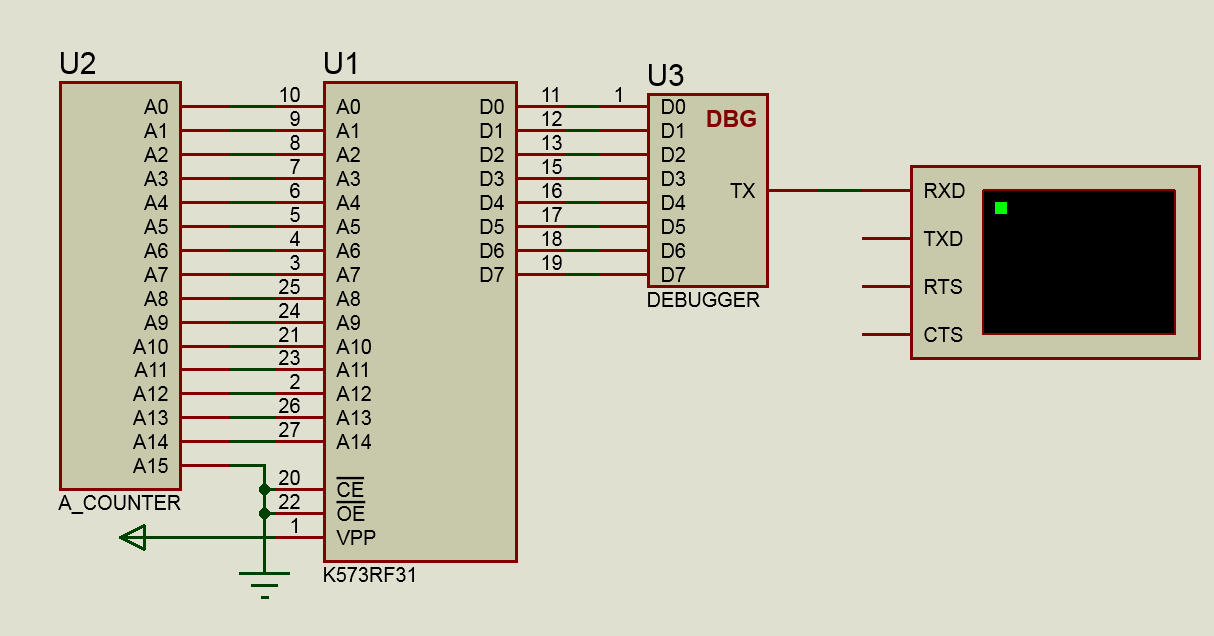
This is the simplest binary counter with an internal clock generator, all its outputs are outputs.
Each model has a DLL that describes the behavior of the model and its interaction with the outside world. In our case, all dll models will have the same, but the scripts will be different. So, create a model:
device_pins is a required global variable containing a description of the device pins. At this stage, the library only supports digital devices. Support for analog and mixed types in the process.
is_digital - our output works only with logical levels, while only true
name is possible - the name of the output on a graphical model. It should exactly match - the binding of the output inside Proteus goes by name.
The two remaining fields speak for themselves - the pin switching time in picoseconds.
In fact, there is no strict need to create something in a script. You can write nothing at all - there will be a dummy model, but for minimal functionality you need to create the device_simulate function . This function will be called when the state of the nodes (conductors) changes, for example, the logical level changes. There is a device_init function . it is called (if exists) once immediately after loading the model.
To set the output state to one of the levels, there is the set_pin_state function , the first argument it takes the name of the output, the second - the desired state, for example, SHI, SLO, FLT, and so on.
First, let us make all the outputs at logical 0, with using single line /
We can refer to the output both through a global variable, for example, A0 , and through its name as a string constant “A0” through the global environment table _G
Now we need to implement the counter itself; Let's start with the master oscillator. To do this, there is a timer_callback function that takes two arguments - time and event number.
Add the following call to device_init after setting the output state:
PC_EVENT is a numerical variable containing the event code (we must declare it globally)
NOW means that you need to call the event handler after 0 picoseconds from the current time (the function takes a pic of a second as an argument )
And here is the function handler
On an event, the set_pin_bool function is called , which controls the output by accepting as an argument one of two states - 1/0.
You may notice that after switching the output, set_callback is called again, because this function schedules non-periodic events. The difference in the time setting is due to the fact that set_callback will be called in the future, so we need to add the time difference, and time just contains the current system time
Everything else - declaration, model initialization, and so on is done on the library side. Although, of course, all the same can be done in C, and Lua can be used for prototyping, since the names of the functions are identical.
We start the simulation and observe the work of our model
The main goal was to facilitate the writing of models and their debugging, so we will consider some options for displaying useful information
4 functions for outputting to the message log, the last two automatically leading to the stop of the simulation
Thanks to the capabilities of Lua, you can easily, conveniently, quickly and clearly display any information you need:
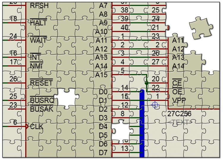
Now let's move on to our second model - ROM chips, and look at
We will model our ROM and make it run during operation.
Announcements of conclusions here are no different, but we need to add the properties of our microcircuit, first of all - the ability to load a memory dump from a file:
This is done in a text script when creating the model:
Now let’s make it so that when the simulation was paused, you could see important information about the model, such as the contents of its memory, the contents of the address bus, data bus, and operating time. To output binary data in a convenient form, there is memory_popup.
The on_suspend function is called (if declared by the user) during pause. If the window is not created, create it.
The memory is transferred to the library as a pointer, then you do not need to release anything later - everything will be done by the Lua garbage collector. And create a debug window of the type where we need the variables and for masquerading we will dump 32 bytes from the offset 0x1000:
Finally, we will implement the algorithm of the ROM itself, ignoring OE, VPP and other CE conclusions

Let's do something for our "debugger":
An interesting question that worried me. I took the model of the 4040 binary counter that comes with the Proteus 7 and made my analogue.
Using a pulse generator, it fed an input signal to both models with a frequency of 100 kHz
Proteus's 4040 = 15-16% CPU Load
Library C = 25-28% CPU Load
Library and Lua 5.2 = 98-100% CPU Load
Library and Lua 5.3a = 76- 78% CPU Load
I didn’t compare the sources, but apparently very optimized the virtual machine in version 5.3. Nevertheless, it is quite tolerant for the convenience of work.
And I didn’t even start to deal with optimization issues.
This whole project was born as a spontaneous idea, and much more needs to be done:
Of course, I would like to find like-minded people who want to help if not by participating in writing the code, then by ideas and feedback. Indeed, now much is hardcoded for the goals and objectives that I needed.
Repository with code.
The finished library and debugging symbols for GDB are here .
Pretty soon the question arose: what to do with elements that are absent in Proteus?
Many resources describe in detail how to create your own C ++ model in Visual Studio.
Unfortunately, when building under Linux, this option is not very convenient. And what if you don’t know C ++ or need to edit the model on the fly for debugging?
And I just want to focus on modeling, simplifying everything else as much as possible.
So the idea came up to do simulation models using scripts - on Lua.
For those interested, I ask for a cut (2Mb gifs).
Why is it necessary
If you forget about all kinds of exotic things, like writing a processor model, I have long lost the habit of doing anything in the simulator - I connected the sensors to various kinds of debugs, an oscilloscope in my hands, a multimeter, JTAG / UART and debug myself.
But when it was necessary to check the logic of the program in case of GPS / motion failure and the like, I had to write GPS emulation on another microcontroller.
When it was necessary to do telemetry for a machine using the KWP2000 protocol, debugging live was inconvenient and dangerous. Yes, and if one - oh how uncomfortable.
The ability to debug / test on the road or somewhere where to carry the entire gentleman's kit with you is simply inconvenient (it is primarily about hobby projects) is a good help, so there is room for the simulator.
Visual Studio C ++ and GCC
I write all the software under GCC and I also wanted to build the model under it, using the developed libraries and code that it would be difficult to build under MSVS. The problem was that the assembled under mingw32 DLL hung Proteus. Various methods were tried including manipulations with __thiscall and comrades, and the options with assembler call hacks did not suit.
A moonglow friend with vast experience in such matters suggested and showed how to rewrite the C ++ interface in C using virtual tables. Of the amenities, in addition to the possibility of assembling under Linux "without interruption from production", the ability, in theory, to write models even on Fortran - would be a desire.
Mimic under C ++
The idea of "emulating" virtual classes in practice looks like this:
The original C ++ virtual class header looks like this
class IDSIMMODEL
{
public:
	virtual INT  isdigital ( CHAR* pinname ) = 0;
	virtual VOID setup ( IINSTANCE* instance, IDSIMCKT* dsim ) = 0;
	virtual VOID runctrl ( RUNMODES mode ) = 0;
	virtual VOID actuate ( REALTIME time, ACTIVESTATE newstate ) = 0;
	virtual BOOL indicate ( REALTIME time, ACTIVEDATA* newstate ) = 0;
	virtual VOID simulate ( ABSTIME time, DSIMMODES mode ) = 0;
	virtual VOID callback ( ABSTIME time, EVENTID eventid ) = 0;
};
And here is the C version; this is our pseudo-class and its virtual table
struct IDSIMMODEL
{
	IDSIMMODEL_vtable* vtable;
};
Now we create a structure with pointers to functions that are inside the class (we will create them and declare them separately)
struct IDSIMMODEL_vtable
{
	int32_t __attribute__ ( ( fastcall ) ) ( *isdigital ) ( IDSIMMODEL* this, EDX, CHAR* pinname );
	void __attribute__ ( ( fastcall ) ) ( *setup ) ( IDSIMMODEL* this, EDX, IINSTANCE* inst, IDSIMCKT* dsim );
	void __attribute__ ( ( fastcall ) ) ( *runctrl ) ( IDSIMMODEL* this, EDX, RUNMODES mode );
	void __attribute__ ( ( fastcall ) ) ( *actuate ) ( IDSIMMODEL* this, EDX, REALTIME atime, ACTIVESTATE newstate );
	bool __attribute__ ( ( fastcall ) ) ( *indicate ) ( IDSIMMODEL* this, EDX, REALTIME atime, ACTIVEDATA* data );
	void __attribute__ ( ( fastcall ) ) ( *simulate ) ( IDSIMMODEL* this, EDX, ABSTIME atime, DSIMMODES mode );
	void __attribute__ ( ( fastcall ) ) ( *callback ) ( IDSIMMODEL* this, EDX, ABSTIME atime, EVENTID eventid );
};
We write the necessary functions and create one instance of our "class", which we will use
IDSIMMODEL_vtable VSM_DEVICE_vtable =
{
	.isdigital      = vsm_isdigital,
	.setup          = vsm_setup,
	.runctrl        = vsm_runctrl,
	.actuate        = vsm_actuate,
	.indicate       = vsm_indicate,
	.simulate       = vsm_simulate,
	.callback       = vsm_callback,
};
IDSIMMODEL VSM_DEVICE =
{
	.vtable = &VSM_DEVICE_vtable,
};
And so on, with all the classes we need. Since calling such a structure is not very convenient, wrapper functions were written, some things were automated, missing, often used functions were added. Even while writing this article, I added a lot of new things, looking at work from the other side.
“Make it as simple as possible, but not easier.”
As a result, the code grew and the feeling that something needs to be changed grew more and more: it took no less time and effort to create a model than to write the same emulator for a microcontroller. In the process of debugging models, it was constantly necessary to change something, to experiment. I had to reassemble the model on every little thing, and work with text data in C leaves much to be desired. Familiar people who would be interested in this too were scared of C (someone uses
I remembered about Lua: it integrates perfectly with C, fast, compact, visual, dynamic typing - all that is needed. As a result, I duplicated all C functions in Lua with the same names, getting a completely self-sufficient way to create models that do not require reassembly at all. You can just take the dll and describe any model only on Lua. It is enough to stop the simulation, correct the text script, and again into battle.
Modeling in Lua
The main testing was conducted in Proteus 7, but the models created from scratch and imported into the 8th version behaved excellently.
Let's create some simple models and see how and what we can do using their example.
I will not describe how to create a graphical model itself, it is perfectly described here and here , so I will focus on writing code.
Here are 3 devices that we will consider. At first I wanted to start with a blinking LED, but then I decided that it was too dull, I hope it was right.
Let's start with A_COUNTER:
This is the simplest binary counter with an internal clock generator, all its outputs are outputs.
Each model has a DLL that describes the behavior of the model and its interaction with the outside world. In our case, all dll models will have the same, but the scripts will be different. So, create a model:
Model description
device_pins =
{
    {is_digital=true, name = "A0", on_time=100000, off_time=100000},
    {is_digital=true, name = "A1", on_time=100000, off_time=100000},
    {is_digital=true, name = "A2", on_time=100000, off_time=100000},
    {is_digital=true, name = "A3", on_time=100000, off_time=100000},
    --тут пропущены однотипные определения для остальных выводов
    --чтобы не прятать под кат
    {is_digital=true, name = "A15", on_time=100000, off_time=100000},
}
device_pins is a required global variable containing a description of the device pins. At this stage, the library only supports digital devices. Support for analog and mixed types in the process.
is_digital - our output works only with logical levels, while only true
name is possible - the name of the output on a graphical model. It should exactly match - the binding of the output inside Proteus goes by name.
The two remaining fields speak for themselves - the pin switching time in picoseconds.
Required User-Defined Functions
In fact, there is no strict need to create something in a script. You can write nothing at all - there will be a dummy model, but for minimal functionality you need to create the device_simulate function . This function will be called when the state of the nodes (conductors) changes, for example, the logical level changes. There is a device_init function . it is called (if exists) once immediately after loading the model.
To set the output state to one of the levels, there is the set_pin_state function , the first argument it takes the name of the output, the second - the desired state, for example, SHI, SLO, FLT, and so on.
First, let us make all the outputs at logical 0, with using single line /
We can refer to the output both through a global variable, for example, A0 , and through its name as a string constant “A0” through the global environment table _G
function device_init()
    for k, v in pairs(device_pins) do set_pin_state(_G[v.name], SLO) end
end
Now we need to implement the counter itself; Let's start with the master oscillator. To do this, there is a timer_callback function that takes two arguments - time and event number.
Add the following call to device_init after setting the output state:
set_callback(NOW, PC_EVENT)
PC_EVENT is a numerical variable containing the event code (we must declare it globally)
NOW means that you need to call the event handler after 0 picoseconds from the current time (the function takes a pic of a second as an argument )
And here is the function handler
function timer_callback(time, eventid)
    if eventid == PC_EVENT then
        for k, v in pairs(device_pins) do
            set_pin_bool(_G[v.name], get_bit(COUNTER, k) )
        end
        COUNTER = COUNTER + 1
        set_callback(time + 100 * MSEC, PC_EVENT)
    end
end
On an event, the set_pin_bool function is called , which controls the output by accepting as an argument one of two states - 1/0.
You may notice that after switching the output, set_callback is called again, because this function schedules non-periodic events. The difference in the time setting is due to the fact that set_callback will be called in the future, so we need to add the time difference, and time just contains the current system time
So that's what happened
device_pins =
{
    {is_digital=true, name = "A0", on_time=100000, off_time=100000},
    {is_digital=true, name = "A1", on_time=100000, off_time=100000},
    {is_digital=true, name = "A2", on_time=100000, off_time=100000},
    {is_digital=true, name = "A3", on_time=100000, off_time=100000},
    {is_digital=true, name = "A4", on_time=100000, off_time=100000},
    {is_digital=true, name = "A5", on_time=100000, off_time=100000},
    {is_digital=true, name = "A6", on_time=100000, off_time=100000},
    {is_digital=true, name = "A7", on_time=100000, off_time=100000},
    {is_digital=true, name = "A8", on_time=100000, off_time=100000},
    {is_digital=true, name = "A9", on_time=100000, off_time=100000},
    {is_digital=true, name = "A10", on_time=100000, off_time=100000},
    {is_digital=true, name = "A11", on_time=100000, off_time=100000},
    {is_digital=true, name = "A12", on_time=100000, off_time=100000},
    {is_digital=true, name = "A13", on_time=100000, off_time=100000},
    {is_digital=true, name = "A14", on_time=100000, off_time=100000},
    {is_digital=true, name = "A15", on_time=100000, off_time=100000},
}
PC_EVENT = 0
COUNTER = 0
function device_init()
   for k, v in pairs(device_pins) do set_pin_state(_G[v.name], SLO) end
   set_callback(0, PC_EVENT)
end
function timer_callback(time, eventid)
    if eventid == PC_EVENT then
        for k, v in pairs(device_pins) do
            set_pin_bool(_G[v.name], get_bit(COUNTER, k) )
        end
        COUNTER = COUNTER + 1
        set_callback(time + 100 * MSEC, PC_EVENT)
    end
end
Everything else - declaration, model initialization, and so on is done on the library side. Although, of course, all the same can be done in C, and Lua can be used for prototyping, since the names of the functions are identical.
We start the simulation and observe the work of our model
Debugging features
The main goal was to facilitate the writing of models and their debugging, so we will consider some options for displaying useful information
Text messages
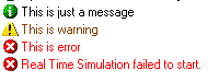
4 functions for outputting to the message log, the last two automatically leading to the stop of the simulation
out_log("This is just a message")
out_warning("This is warning")
out_error("This is error")
out_fatal("This is fatal error")
Thanks to the capabilities of Lua, you can easily, conveniently, quickly and clearly display any information you need:
out_log("We have "..#device_pins.." pins in our device")
Now let's move on to our second model - ROM chips, and look at
Popup windows
We will model our ROM and make it run during operation.
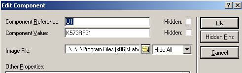
Announcements of conclusions here are no different, but we need to add the properties of our microcircuit, first of all - the ability to load a memory dump from a file:
This is done in a text script when creating the model:
{FILE = "Image File", FILENAME, FALSE ,, Image / *. BIN}
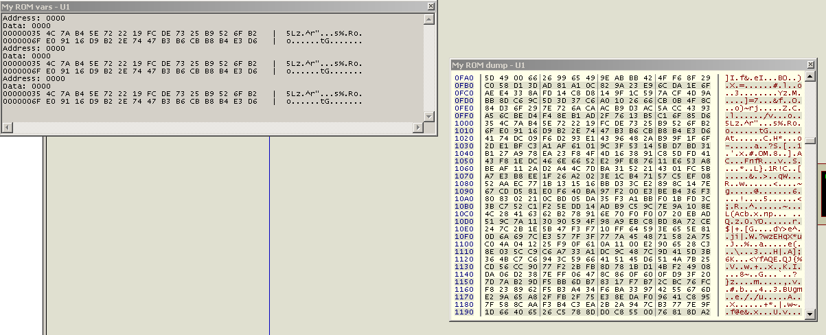
Now let’s make it so that when the simulation was paused, you could see important information about the model, such as the contents of its memory, the contents of the address bus, data bus, and operating time. To output binary data in a convenient form, there is memory_popup.
function device_init()
    local romfile = get_string_param("file")
    rom = read_file(romfile)
    mempop, memid = create_memory_popup("My ROM dump")
    set_memory_popup(mempop, rom, string.len(rom))
end
function on_suspend()
    if nil == debugpop then
        debugpop, debugid = create_debug_popup("My ROM vars")
        print_to_debug_popup(debugpop, string.format("Address: %.4X\nData: %.4X\n", ADDRESS, string.byte(rom, ADDRESS)))
        dump_to_debug_popup(debugpop, rom, 32, 0x1000)
    elseif debugpop then
        print_to_debug_popup(debugpop, string.format("Address: %.4X\nData: %.4X\n", ADDRESS, string.byte(rom, ADDRESS)))
        dump_to_debug_popup(debugpop, rom, 32, 0x1000)
    end
end
The on_suspend function is called (if declared by the user) during pause. If the window is not created, create it.
The memory is transferred to the library as a pointer, then you do not need to release anything later - everything will be done by the Lua garbage collector. And create a debug window of the type where we need the variables and for masquerading we will dump 32 bytes from the offset 0x1000:
Finally, we will implement the algorithm of the ROM itself, ignoring OE, VPP and other CE conclusions
function device_simulate()
    for i = 0, 14 do
        if 1 == get_pin_bool(_G["A"..i]) then
            ADDRESS = set_bit(ADDRESS, i)
        else
            ADDRESS = clear_bit(ADDRESS, i)
        end
    end
    for i = 0, 7 do
        set_pin_bool(_G["D"..i], get_bit(string.byte(rom, ADDRESS), i))
    end
end
Let's do something for our "debugger":
create a software UART, in which we will output the contents of the data bus
device_pins =
{
    {is_digital=true, name = "D0", on_time=1000, off_time=1000},
    {is_digital=true, name = "D1", on_time=1000, off_time=1000},
    {is_digital=true, name = "D2", on_time=1000, off_time=1000},
    {is_digital=true, name = "D3", on_time=1000, off_time=1000},
    {is_digital=true, name = "D4", on_time=1000, off_time=1000},
    {is_digital=true, name = "D5", on_time=1000, off_time=1000},
    {is_digital=true, name = "D6", on_time=1000, off_time=1000},
    {is_digital=true, name = "D7", on_time=1000, off_time=1000},
    {is_digital=true, name = "TX", on_time=1000, off_time=1000},
}
-- UART events
UART_STOP = 0
UART_START = 1
UART_DATA=2
-- Constants
BAUD=9600
BAUDCLK = SEC/BAUD
BIT_COUNTER = 0
-----------------------------------------------------------------
DATA_BUS = 0
function device_init()
end
function device_simulate()
    for i = 0, 7 do
        if 1 == get_pin_bool(_G["D"..i]) then
            DATA_BUS = set_bit(DATA_BUS, i)
        else
            DATA_BUS = clear_bit(DATA_BUS, i)
        end
    end
    uart_send(string.format("[%d] Fetched opcode %.2X\r\n", systime(), DATA_BUS))
end
function timer_callback(time, eventid)
    uart_callback(time, eventid)
end
function uart_send (string)
    uart_text = string
    char_count = 1
    set_pin_state(TX, SHI) -- set TX to 1 in order to have edge transition
    set_callback(BAUDCLK, UART_START) --schedule start
end
function uart_callback (time, event)
    if event == UART_START then
        next_char = string.byte(uart_text, char_count)
        if next_char == nil then
            return
        end
        char_count = char_count +1
        set_pin_state(TX, SLO)
        set_callback(time + BAUDCLK, UART_DATA)
    end
    if event == UART_STOP then
        set_pin_state(TX, SHI)
        set_callback(time + BAUDCLK, UART_START)
    end
    if event == UART_DATA then
        if get_bit(next_char, BIT_COUNTER) == 1 then
            set_pin_state(TX, SHI)
        else
            set_pin_state(TX, SLO)
        end
        if BIT_COUNTER == 7 then
            BIT_COUNTER = 0
            set_callback(time + BAUDCLK, UART_STOP)
            return
        end
        BIT_COUNTER = BIT_COUNTER + 1
        set_callback(time + BAUDCLK, UART_DATA)
    end
end
Performance
An interesting question that worried me. I took the model of the 4040 binary counter that comes with the Proteus 7 and made my analogue.
Using a pulse generator, it fed an input signal to both models with a frequency of 100 kHz
Proteus's 4040 = 15-16% CPU Load
Library C = 25-28% CPU Load
Library and Lua 5.2 = 98-100% CPU Load
Library and Lua 5.3a = 76- 78% CPU Load
I didn’t compare the sources, but apparently very optimized the virtual machine in version 5.3. Nevertheless, it is quite tolerant for the convenience of work.
And I didn’t even start to deal with optimization issues.
This whole project was born as a spontaneous idea, and much more needs to be done:
Immediate plans
- Fix explicit bugs in the code
- Minimize the ability to shoot yourself in the foot
- Document code under Doxygen
- Maybe switch to luaJIT
- Implement analog and mixed device types
- With plugin for IDA
Of course, I would like to find like-minded people who want to help if not by participating in writing the code, then by ideas and feedback. Indeed, now much is hardcoded for the goals and objectives that I needed.
Download without ads and SMS
Repository with code.
The finished library and debugging symbols for GDB are here .