 May 3, 2014 at 06:36
Arduino drives an industrial freight elevator
Disclaimer: If you are good at electronics, then some of the technical solutions described in this article will shock and horrify you, as well as cause an irresistible desire to tear your hands off to the author. I warned.
A little about how the freight elevators are arranged andnot a big story of creating a control system for a six-story freight elevator based on the Arduino board of the Seeeduino compatible controller (ATmega 328). 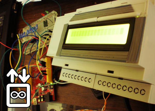
Quite a lot of pictures and letters!
I work as an electrician in a small company that manufactures and installs freight elevators. Students engaged in a similar profile are actively accepting this work and they willingly agree. In terms of creativity, such work is just a paradise - no one gets into electrical matters and there is complete freedom of action both in the choice of wiring materials (if only not very expensive), and in the ways of selling the finished product (if only it works). Since the bulk of orders comes down to the simplest lifts with two stops, this work cannot be called difficult, and even a student without experience will quickly get involved.
In general, a fertile field for experimentation !
As a rule, all electrics are assembled according to ready-made circuits, which are built on primitive logic using relays. The main elements in a typical solution are two magnetic starters (PV and PN in the figure), which start the electric hoist (motor with gear and drum, on which the cable is wound), floor limit switches (K1 and K2), start control buttons (KN) and limit switches of the safety circuit (CD), which block the start of the elevator (for example, if the doors of the shaft are open).
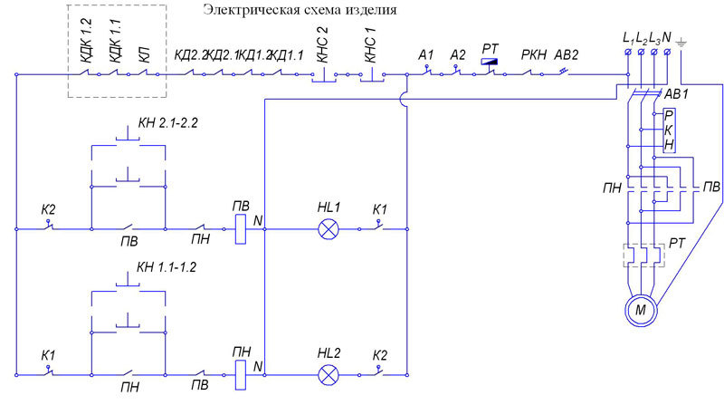
The whole logic of the operation of a freight elevator boils down to the fact that while all the limit switches in the safety circuit are pressed (in the figure it starts from L1 to the limit switches K1 and 2), phasing is observed, the engine does not overheat and the Stop button is not pressed, the elevator control buttons are pressed voltage. If one of the buttons is pressed, the corresponding magnetic starter starts, which, when activated, essentially forms a trigger that opens as soon as the elevator reaches the floor limit switch.
The whole gimp begins after the number of floors on which the freight elevator is supposed to arrive is more than two. For example, for a three-story lift, the circuit will replenish with one intermediate relay, which will switch the circuit to provide a stop on the middle floor. For a four-story elevator, two relays are needed, three for a five-story elevator and so on. And if you saw through the previous picture like a nut, then I present to your attention the control scheme of a nine-story freight elevator:
Nowadays, such a complexity of the management scheme is a mortal sin. Of course, the first thing a reasonable engineer will propose to do is use a programmable logic controller (PLC). True, the cost of components in this case will increase. But why not use the cheap Arduino here? After scouring the net, I found some interesting projects with passenger elevator models from the familiar LEGO and decided that this shawl should definitely cope with the freight elevator. Just in time, an order was received for a six-story lift.
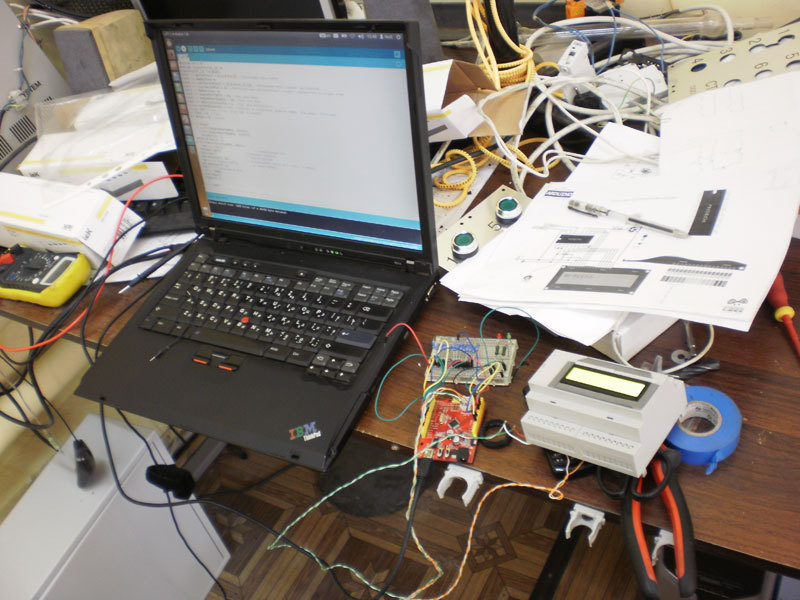
In addition, I already had a Seeeduino board (ATmega 328) and a Chinese LCD display for quite some time. If we sculpt the controller, then with a display! And first of all, I calculated the number of ports on the board that can be used. And there are 14 discrete and 6 analog ones on Seeeduino (which, of course, also work as discrete ones). The idea was simple: hang each button and limit floor switch on your port, and turn on the magnetic starters using a 5VDC / 220VAC relay. The security chain must also have its own port. In total, for a six-story freight elevator, 13 digital inputs and two relay outputs are required. But where to connect the display? The shift register PCF8574 comes to the rescue, which allows you to control it in just two wires (there is a post about this) Thus, using a breadboard, 13 pull-up resistors and two light bulbs simulating a “start up” relay and a “start down” relay, I wrote a control program (there it’s even a shame to show me a cycle on a cycle and a cycle). Unfortunately, the display is not supported by the Cyrillic alphabet, therefore it only displays messages such as “Lift on a Floor” and “Security Circuit Broken!”
If everything went smoothly with the number of ports, then the combination of logical levels turned out to be the first big problem. The fact is that the electrical products used by us are designed for 220VAC *. That is, when you press a button or limit switch, the real phase comes to the wire, while Arduino uses 5VDC logic. Since I’m not a pro in electronics, I turned to the radio forum for help, and using tips I built up such an optocoupler-based circuit:
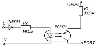
It worked perfectly with the LED, and I am guided by the Cave Johnson principle (“we just throw science into the wall and look, that sticks ”) decided to immediately solder it to the board.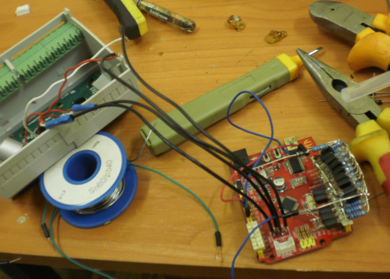
And, of course, it was a failure. Arduino not only did not see the logical unit on the port, but also the optocouplers often merrily burned along with the resistors. Meanwhile, the customer was already waiting for his elevator. And there was nothing left but to admit defeat and make the circuit as before, on the relay. Well, on the relay, so on the relay, I decided, threw out the optocouplers and took thirteen intermediate relays for use as a galvanic isolation. Each relay has its own button and floor limit switch.
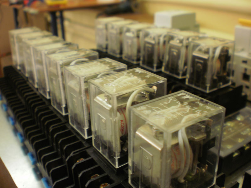
After such an original solution to the problem of logical levels, I turned to the task of turning on magnetic starters. It is worth mentioning that the 5VDC / 220VAC relays are not directly connected to the Arduino ports, but according to the scheme with a transistor and a diode. However, you can just buy a finished block.
Nevertheless, in the matter of controlling such a load as 220V magnetic starters, the second and biggest problem awaited me - pick-ups. Since I stuffed the Arduino, the display and both relays quite tightly into one case, when the magnetic starter was turned on, the display began to show krakozyabry instead of letters, and the controller could completely freeze. There was less time left, and I decided to make an impromptu shielding from kitchen foil.
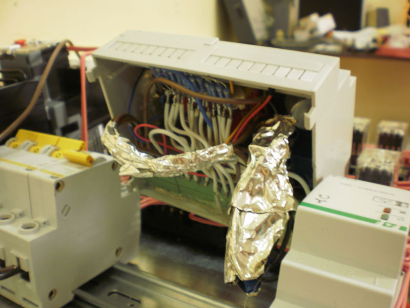
No matter how ridiculous everything looked, but it helped. I searched the network for any solutions, but found only offers to use ferrite rings or optocouplers again, with which I no longer made friends.
The whole assembly assembly:

Then follows a trip to the facility for the installation of electrical equipment. This is a plastic packaging factory. The controller will control this handsome man with a carrying capacity of three tons:
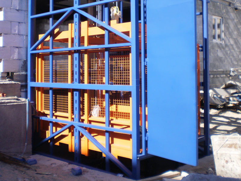
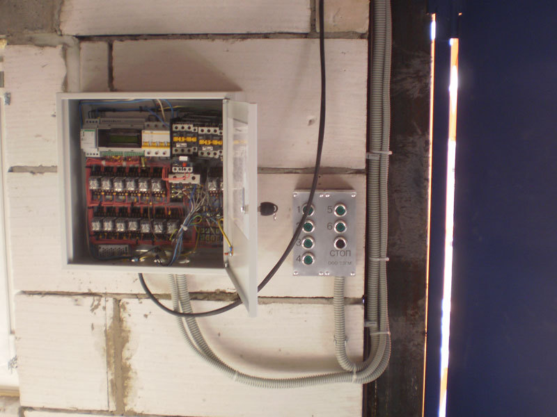
Installing electricians is a tedious task - you have to climb the mine all day, stretching the wires, and then, sometimes hanging in an uncomfortable position, connect them in the terminal blocks in the junction boxes. But this is not the worst problem that awaits you if you decide to make your controller. The worst thing, as I said, is the tip. It turned out that pickups from a magnetic starter that is idling and pickups from a starter that closes or (worst of all) disconnects the power of an eight-kilowatt engine is not the same thing at all (Who would have thought!). Whatever screens I fence, sparks on the contact group of the starter reduced their effect to zero. And although the controller did not break, the display gave out nonsense instead of informational messages. After much ordeal, in the end, I fenced off the magnetic starters from the controller with a steel plate connected to the neutral (unfortunately there was no grounding at the time of installation), and the display problem was solved programmatically using the delay () function ;. As soon as the program started the engine or stopped it, the second delay () turned on; after which a message was displayed.
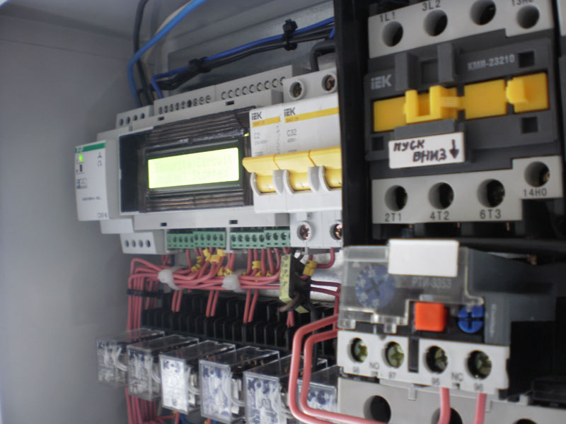
Of course, I could not completely trust the controller with the issue of emergency or emergency stop of the elevator. As soon as the power in the safety circuit disappears, the relay opens the power on the starters, and sends a signal to the arduino port. And even if the controller freezes for some reason, the lift will still be stopped. In addition, the scheme provides for a remote reboot of the system from any floor by pressing the Stop button for more than two seconds.
Video work, I apologize in advance for the quality.
Results:
The price turned out quite inexpensively: Relay - 80 r / pc * 13pcs = 1040r, display + Arduino = 1000r, power supply, case, terminal blocks and resistors = 1000r.
In total, the controller cost around 3000r, while the most budget PLC that can cope with such a task will be released at least 7000r.
Reliability - time will tell. I already saw the burnt PLCs, so it's not a fact that the Arduino will be worse. In this parameter, the relay circuit is still out of competition. Using the controller allowed to reduce the number of wires, which means to facilitate the work of crimping and marking, as well as simplify installation.
Summing up, I would like to wish the Arduino platform development towards integration with power circuits (well, for example, the appearance of ready-made optical isolation units) in the future. I know that many consider Arduino to be just a child’s toy. However, progress does not stand still and everything goes to the point that a person who is familiar with electronics will be able to assemble the most complex devices without looking at any problems like “which resistor to choose so that the optocoupler doesn’t burn out” and free up more time for technical creativity.
Thanks for attention!
PS:
* Yes, I understand that 220V is not the best choice for control circuits. The fact is that before my arrival the company had historically had such a thing (apparently it was too lazy to bother with the converters), well, it’s also difficult for suppliers to get the buttons and starters for the required voltage. To reassure you, I will say that many customers connect freight elevators through an RCD, which I advise everyone.
UPD:
Gentlemen, the freight elevator, and people are forbidden to ride it. This is clearly written on every door on every floor. The mine doors are blocked by electric locks, which are completely independent of the controller, for the duration of the operation.
All emergency situations already have their own answer. For example, in the event of a cable break - a mechanical catcher of abrupt weight loss (Ottis himself invented it by the way), in case of overload or jamming of the cab - a thermal relay and overload limiters, also working independently of the controller.
In short, the controller only deals with the logic of starting the elevator to the floors, and the security system remains completely unchanged.
UPD2:
Here is the text of the program (I am the same programmer as the electronics engineer)
A little about how the freight elevators are arranged and
Quite a lot of pictures and letters!
I work as an electrician in a small company that manufactures and installs freight elevators. Students engaged in a similar profile are actively accepting this work and they willingly agree. In terms of creativity, such work is just a paradise - no one gets into electrical matters and there is complete freedom of action both in the choice of wiring materials (if only not very expensive), and in the ways of selling the finished product (if only it works). Since the bulk of orders comes down to the simplest lifts with two stops, this work cannot be called difficult, and even a student without experience will quickly get involved.
In general, a fertile field for experimentation !
As a rule, all electrics are assembled according to ready-made circuits, which are built on primitive logic using relays. The main elements in a typical solution are two magnetic starters (PV and PN in the figure), which start the electric hoist (motor with gear and drum, on which the cable is wound), floor limit switches (K1 and K2), start control buttons (KN) and limit switches of the safety circuit (CD), which block the start of the elevator (for example, if the doors of the shaft are open).
The whole logic of the operation of a freight elevator boils down to the fact that while all the limit switches in the safety circuit are pressed (in the figure it starts from L1 to the limit switches K1 and 2), phasing is observed, the engine does not overheat and the Stop button is not pressed, the elevator control buttons are pressed voltage. If one of the buttons is pressed, the corresponding magnetic starter starts, which, when activated, essentially forms a trigger that opens as soon as the elevator reaches the floor limit switch.
The whole gimp begins after the number of floors on which the freight elevator is supposed to arrive is more than two. For example, for a three-story lift, the circuit will replenish with one intermediate relay, which will switch the circuit to provide a stop on the middle floor. For a four-story elevator, two relays are needed, three for a five-story elevator and so on. And if you saw through the previous picture like a nut, then I present to your attention the control scheme of a nine-story freight elevator:
Nowadays, such a complexity of the management scheme is a mortal sin. Of course, the first thing a reasonable engineer will propose to do is use a programmable logic controller (PLC). True, the cost of components in this case will increase. But why not use the cheap Arduino here? After scouring the net, I found some interesting projects with passenger elevator models from the familiar LEGO and decided that this shawl should definitely cope with the freight elevator. Just in time, an order was received for a six-story lift.
In addition, I already had a Seeeduino board (ATmega 328) and a Chinese LCD display for quite some time. If we sculpt the controller, then with a display! And first of all, I calculated the number of ports on the board that can be used. And there are 14 discrete and 6 analog ones on Seeeduino (which, of course, also work as discrete ones). The idea was simple: hang each button and limit floor switch on your port, and turn on the magnetic starters using a 5VDC / 220VAC relay. The security chain must also have its own port. In total, for a six-story freight elevator, 13 digital inputs and two relay outputs are required. But where to connect the display? The shift register PCF8574 comes to the rescue, which allows you to control it in just two wires (there is a post about this) Thus, using a breadboard, 13 pull-up resistors and two light bulbs simulating a “start up” relay and a “start down” relay, I wrote a control program (there it’s even a shame to show me a cycle on a cycle and a cycle). Unfortunately, the display is not supported by the Cyrillic alphabet, therefore it only displays messages such as “Lift on a Floor” and “Security Circuit Broken!”
If everything went smoothly with the number of ports, then the combination of logical levels turned out to be the first big problem. The fact is that the electrical products used by us are designed for 220VAC *. That is, when you press a button or limit switch, the real phase comes to the wire, while Arduino uses 5VDC logic. Since I’m not a pro in electronics, I turned to the radio forum for help, and using tips I built up such an optocoupler-based circuit:
It worked perfectly with the LED, and I am guided by the Cave Johnson principle (“we just throw science into the wall and look, that sticks ”) decided to immediately solder it to the board.
And, of course, it was a failure. Arduino not only did not see the logical unit on the port, but also the optocouplers often merrily burned along with the resistors. Meanwhile, the customer was already waiting for his elevator. And there was nothing left but to admit defeat and make the circuit as before, on the relay. Well, on the relay, so on the relay, I decided, threw out the optocouplers and took thirteen intermediate relays for use as a galvanic isolation. Each relay has its own button and floor limit switch.
After such an original solution to the problem of logical levels, I turned to the task of turning on magnetic starters. It is worth mentioning that the 5VDC / 220VAC relays are not directly connected to the Arduino ports, but according to the scheme with a transistor and a diode. However, you can just buy a finished block.
Nevertheless, in the matter of controlling such a load as 220V magnetic starters, the second and biggest problem awaited me - pick-ups. Since I stuffed the Arduino, the display and both relays quite tightly into one case, when the magnetic starter was turned on, the display began to show krakozyabry instead of letters, and the controller could completely freeze. There was less time left, and I decided to make an impromptu shielding from kitchen foil.
No matter how ridiculous everything looked, but it helped. I searched the network for any solutions, but found only offers to use ferrite rings or optocouplers again, with which I no longer made friends.
The whole assembly assembly:
Then follows a trip to the facility for the installation of electrical equipment. This is a plastic packaging factory. The controller will control this handsome man with a carrying capacity of three tons:
Installing electricians is a tedious task - you have to climb the mine all day, stretching the wires, and then, sometimes hanging in an uncomfortable position, connect them in the terminal blocks in the junction boxes. But this is not the worst problem that awaits you if you decide to make your controller. The worst thing, as I said, is the tip. It turned out that pickups from a magnetic starter that is idling and pickups from a starter that closes or (worst of all) disconnects the power of an eight-kilowatt engine is not the same thing at all (Who would have thought!). Whatever screens I fence, sparks on the contact group of the starter reduced their effect to zero. And although the controller did not break, the display gave out nonsense instead of informational messages. After much ordeal, in the end, I fenced off the magnetic starters from the controller with a steel plate connected to the neutral (unfortunately there was no grounding at the time of installation), and the display problem was solved programmatically using the delay () function ;. As soon as the program started the engine or stopped it, the second delay () turned on; after which a message was displayed.
Of course, I could not completely trust the controller with the issue of emergency or emergency stop of the elevator. As soon as the power in the safety circuit disappears, the relay opens the power on the starters, and sends a signal to the arduino port. And even if the controller freezes for some reason, the lift will still be stopped. In addition, the scheme provides for a remote reboot of the system from any floor by pressing the Stop button for more than two seconds.
Video work, I apologize in advance for the quality.
Results:
The price turned out quite inexpensively: Relay - 80 r / pc * 13pcs = 1040r, display + Arduino = 1000r, power supply, case, terminal blocks and resistors = 1000r.
In total, the controller cost around 3000r, while the most budget PLC that can cope with such a task will be released at least 7000r.
Reliability - time will tell. I already saw the burnt PLCs, so it's not a fact that the Arduino will be worse. In this parameter, the relay circuit is still out of competition. Using the controller allowed to reduce the number of wires, which means to facilitate the work of crimping and marking, as well as simplify installation.
Summing up, I would like to wish the Arduino platform development towards integration with power circuits (well, for example, the appearance of ready-made optical isolation units) in the future. I know that many consider Arduino to be just a child’s toy. However, progress does not stand still and everything goes to the point that a person who is familiar with electronics will be able to assemble the most complex devices without looking at any problems like “which resistor to choose so that the optocoupler doesn’t burn out” and free up more time for technical creativity.
Thanks for attention!
PS:
* Yes, I understand that 220V is not the best choice for control circuits. The fact is that before my arrival the company had historically had such a thing (apparently it was too lazy to bother with the converters), well, it’s also difficult for suppliers to get the buttons and starters for the required voltage. To reassure you, I will say that many customers connect freight elevators through an RCD, which I advise everyone.
UPD:
Gentlemen, the freight elevator, and people are forbidden to ride it. This is clearly written on every door on every floor. The mine doors are blocked by electric locks, which are completely independent of the controller, for the duration of the operation.
All emergency situations already have their own answer. For example, in the event of a cable break - a mechanical catcher of abrupt weight loss (Ottis himself invented it by the way), in case of overload or jamming of the cab - a thermal relay and overload limiters, also working independently of the controller.
In short, the controller only deals with the logic of starting the elevator to the floors, and the security system remains completely unchanged.
UPD2:
Here is the text of the program (I am the same programmer as the electronics engineer)









