Signed Distance Field or how to make a vector from a raster
Today we are talking about generating images with a distance map (Signed Distance Field). This type of image is noteworthy in that it actually allows you to get "vector" graphics on a video accelerator, and for nothing. Valve was one of the first to offer this rasterization method in Team Fortress 2 for scalable decals in 2007, but it is still not very popular, although it allows rendering fonts of excellent quality using a texture of only 256x256 pixels. This method is perfect for modern high-definition screens and can seriously save on textures in games, it is not demanding on hardware and works great on smartphones.
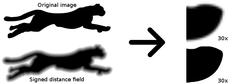
The trick is to create such a specially prepared distance map that when using the simplest shader, an ideal vector illustration is obtained. Moreover, with the help of shaders, you can get the effects of shadow, glow, volume, etc.
How to create such images? Very simple, ImageMagick allows you to do this with one command:
We could put an end to this, but a full-fledged topic will not work. Well, under the cut - a description of the fast SDF calculation algorithm, an example in C ++ and a few shaders for OpenGL.
The first command at the beginning of this post is the recipe for generating SDF from any black and white raster outline. It is based on ImageMagick's new feature: morphology . Among the morphological transformations, there is also the calculation of a distance map .
Calculation of the distance map is the simplest algorithm. It works on monochrome images where the pixel is either black or white. We consider one of the colors internal and the other external (as you like, the black pixel in this picture with the cheetah will be internal). Sometimes they are called background and foreground colors. For each “internal” pixel of the image, you need to find the closest “external” pixel to it and set the brightness value of this pixel as the Euclidean distanceto the nearest “external” pixel. That is, you need to calculate the distances to all the "external" pixels of the image and select the smallest of them. The resulting distance map is called Distance Field (DF), but so far it does not suit us. To get SDF (Signed DF), invert the image, repeat the algorithm, invert again and add to the previous result.
The intensity value does not need to be set exactly to the distance value: you can scale the “blurry” image depending on the needs. In particular, it is better to use a less blurry map for rendering clear contours, and for special effects such as a shadow or glow, it is better to increase the distance map:
Although ImageMagick is not the fastest and easiest way to create such a map, I think this is the best option, since ImageMagick is present on almost all operating systems and is often used by developers for pipelining sprites. It is enough to complete the script a bit and put the image generation on the stream.
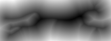
Let's see how it works. If we simply take and apply the morphology operation to our image, we will not get the best result:

Malevich? No, justblacks steal coal at night, there is not enough contrast, it can be quickly pulled out with the parameter
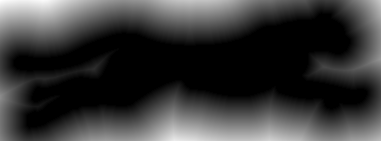
A flaw is immediately evident: a distance map is generated only from the outside. This is a consequence of the fact that the algorithm itself is also two-pass, we repeat the same for the negative:
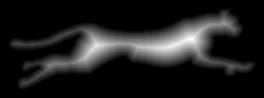
Now the opposite situation - there is not enough card outside.
It remains to combine these two algorithms using an intermediate layer, tighten the contrast and get a furious script from the beginning of the post:
Some explanations:
Well, if there is an original with a higher resolution, then you can do without a trick with increasing the scale and scale already only to a smaller side:
Please note that the Jinc filter “moved” to the end of the chain, as it is intended to improve the quality of sampling while reducing the size of the map. Also, do not clean up
Some controversial issues .
Does it make sense to “stretch” the contrast?In general, theoretically, with increasing contrast, the delta of samples increases, from which antialiasing is then calculated using the hardware interpolation method. In short - you need to stretch, especially if you plan to display clear, smooth contours and effects like shadows are not so important. If the original card will not only stretch, but also shrink, you should not get carried away too much; otherwise, when you reduce the image size, the anti-aliasing, due to the blurry edges of the SDF, will deteriorate.
How does quality depend on the resolution of the SDF card? I tried to plot the PSNR versus map resolution and contrast. In general, the quality increases, but it still depends on the contrast of the card. You can evaluate the dependencies on the chart:
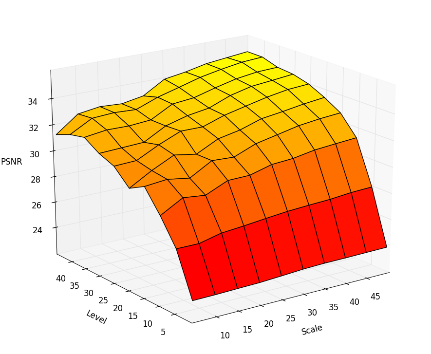
Here Scale is the scale as a percentage of the source, Level - how much the contrast was “stretched”. We can conclude that the dependence on the scale is not very linear, 30% will be a very compromise option, and the contrast rather strongly affects the quality of the contour.
How much does the size of the Euclidean filter affect quality ? Increasing the filter size gives an increase of 0.1 dB + - a penny, in my opinion this is not significant.
How much can you “shrink” the original image? It depends a lot on the shape. SDF does not like sharp corners, and such a smooth picture like the cheetah from the example feels great even on a miniature scale:

The algorithm is simple, but its “forehead” implementation will work for hours: in fact, you need to scan the entire image for each pixel. O (N ^ 2) does not suit us at all. But smart people already thought and came up with an algorithm for accurate (!) DF calculation, which works for O (N). It remains to extend the task to SDF, which is quite simple (see the previous example).
The bottom line. Instead of counting the distance for each pixel, we will perform two consecutive passes through the image, simply incrementing the distance under certain conditions. This is reminiscent of the fast Box-Blur algorithm. Matan can be gleaned from [2], but I will try to explain on the fingers.
I will call the pixel p the element of the array N * M composed of the original image. A pixel is the following structure:
As you can see, there is nothing about brightness, etc. - it is not necessary. The array is formed as follows:
If the pixel of the source image is light, then
If the pixel in the original image is dark, then
Each pixel has 8 neighbors, we number them in this way:
Next, we introduce two auxiliary functions. The function h is needed to calculate the Euclidean distance between the pixel and the neighbor, the function G is needed to calculate the new distance value between the components.
First pass . This passage is performed in direct order (from the upper left corner of the image to the lower right). Pseudocode:
Second pass . This pass is performed in the reverse order (from the lower right corner of the image to the upper left). Pseudocode:
The algorithm needs to be repeated for the negative of the original image. Then, for the two received cards, you need to make the final distance calculation and subtraction to combine the two DF cards into one SDF:
Initially, we kept the Euclidean distance square in the structure, so we need to grind the root. Why you need to add one - don’t ask, the result is empirical and without it it turns out crooked :) The final SDF card is the result of subtracting the second from the first, then you need to scale the value as you like.
In my opinion, even an attempt to explain how it works on the fingers seems very confusing, so I will give the source code in C ++. As an input image, I used QImage from Qt, so as not to spoil the visibility of the process. The source is based on the source [3], but there are bugs there.
A trick is used here: since both passes use a “window” of 1 pixel width, I add a single-pixel border around the original image to avoid checking the borders. For negative, the border also needs to be changed to the opposite value, which was not taken into account in [3].
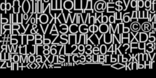
A complete working algorithm can be found in the open source raster font generator UBFG . Example result:
The idea of the inverse transformation (from SDF to raster contour) is based on increasing the contrast to such an extent that blurry edges will not be visible. By changing the contrast of the SDF, you can get various effects, as well as adjust the quality of anti-aliasing of the image. As an example, take the source:
This is also an SDF, just very compressed and reduced in size. Increase it by 16 times:
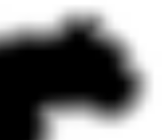
Now, to get a beautiful outline, increase the contrast. I used GIMP for these purposes:
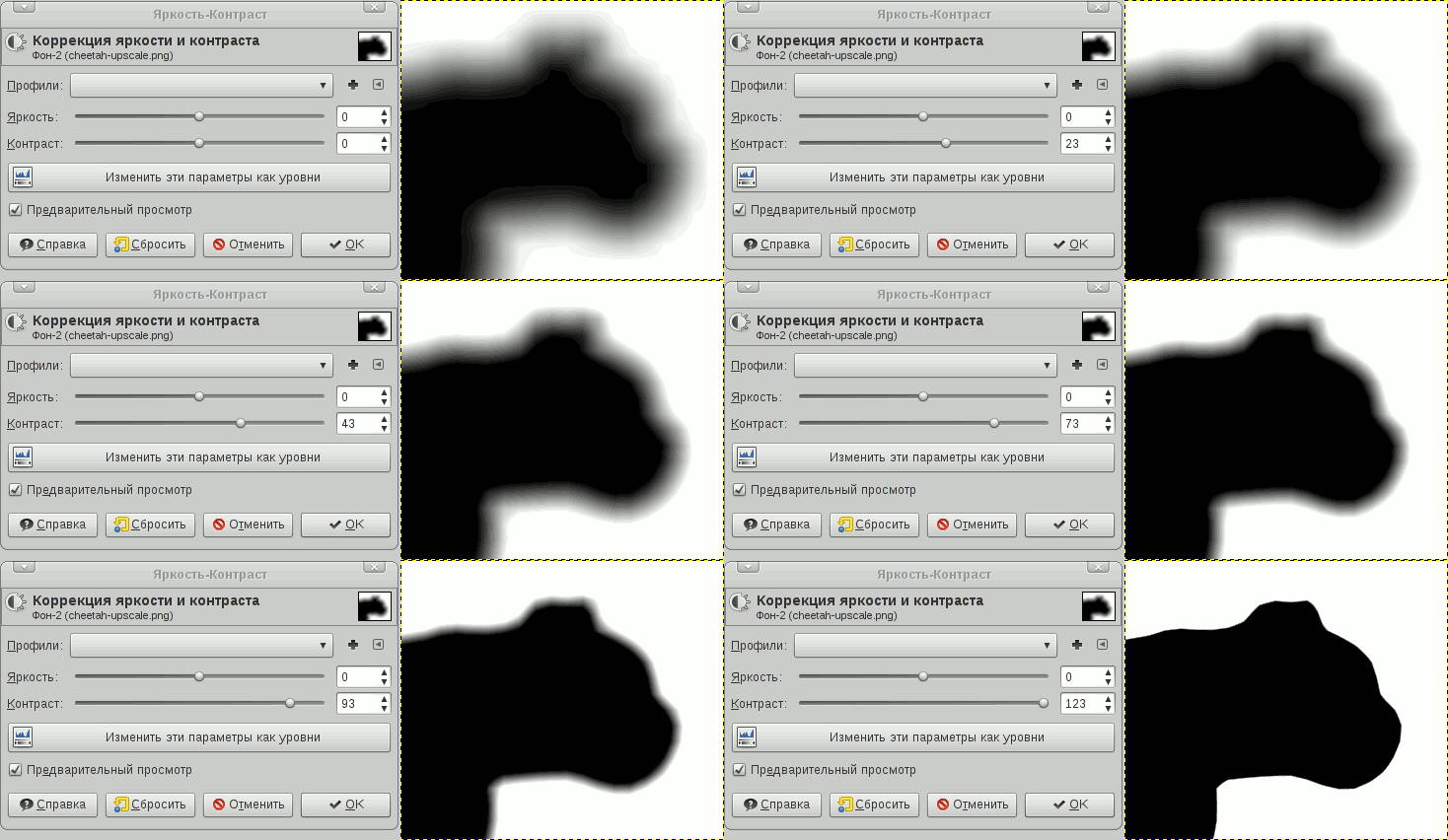
To see the result of using SDF in real time, shaders are indispensable. The simplest alpha test can also be used, but it cuts anti-aliasing at its root. However, the shader used is just a couple of instructions and does not actually affect performance. Moreover, considering that shaders are cheap now, and memory / cache are expensive, you can get good acceleration due to saving video memory.
Now let's see how this business can be used in OpenGL. All examples will be given as pure GLSL source code. You can try it in any shader editor. I tested all the examples in the Kick.js editor , as this is the only editor that allows you to load your textures.
Here we simply draw the contrast relative to the average value (0.5). The strength of the contrast should vary depending on the scale of the texture and the smear of the DF map - the parameter is selected experimentally and set through uniform with a scale factor.
You can slightly improve the quality with a filter
Here the threshold also needs to be selected.
To get this effect, you need to take two thresholds and invert the color:
Result:
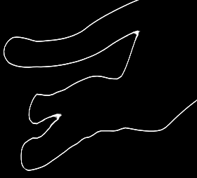
A little more chemistry over the previous example - and we get the glow effect:
To get a shadow, you need to take a color for glow with an offset:
Result:
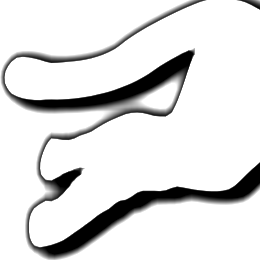
The result may not seem so hot, but this is because I used a map too small:
[1] Improved Alpha-Tested Magnification for Vector Textures and Special Effects is the same article from Valve.
[2] Frank Y. Shih, Yi-Ta Wu. Fast Euclidean distance transformation in two scans using a 3x3 neighborhood - Chinese? No, just a University of New Jersey.
[3] www.codersnotes.com/notes/signed-distance-fields - this is also a fairly fast algorithm, but unfortunately its author made several errors and multiplication is present, which is slightly slower than the algorithm presented in this article.
[4] contourtextures.wikidot.com- Another implementation of the SDF calculation, but its advantage is that it can take into account the smoothing of the edges to determine the nearest points. Nothing is said about performance, but it’s good when there is no way to get a high-resolution original (on the other hand, you can just do the upscale trick). If you had experience using it, unsubscribe in the comments.
[5] gpuhacks.wordpress.com/2013/07/08/signed-distance-field-rendering-of-color-bit-planes - a method of rendering color vector images (suitable for a small number of colors).
[6] distance.sourceforge.net is an interesting resource on which various SDF calculation algorithms are compared.
upd. Thanks to the remark by Bas1l, the algorithm is still not entirely accurate and may give errors in calculating the distance to the nearest neighbors due to an error in the proof. In this paper we presented an improved version of the algorithm.
upd2 . From user achkasov a comment regarding shaders. In the event of sudden transitions, fusions and uneven anti-aliasing may appear on the SDF card. More information about the effect and how to deal with it: iquilezles.org/www/articles/distance/distance.htm
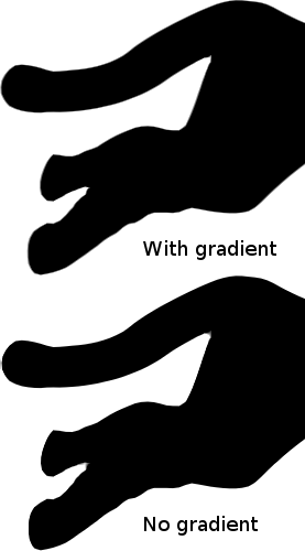
Changing the shader, we get a significant improvement in the area, ahem, tail:
The trick is to create such a specially prepared distance map that when using the simplest shader, an ideal vector illustration is obtained. Moreover, with the help of shaders, you can get the effects of shadow, glow, volume, etc.
How to create such images? Very simple, ImageMagick allows you to do this with one command:
convert in.png -filter Jinc -resize 400% -threshold 30% \( +clone -negate -morphology Distance Euclidean -level 50%,-50% \) -morphology Distance Euclidean -compose Plus -composite -level 45%,55% -resize 25% out.png
We could put an end to this, but a full-fledged topic will not work. Well, under the cut - a description of the fast SDF calculation algorithm, an example in C ++ and a few shaders for OpenGL.
What was that spell?
The first command at the beginning of this post is the recipe for generating SDF from any black and white raster outline. It is based on ImageMagick's new feature: morphology . Among the morphological transformations, there is also the calculation of a distance map .
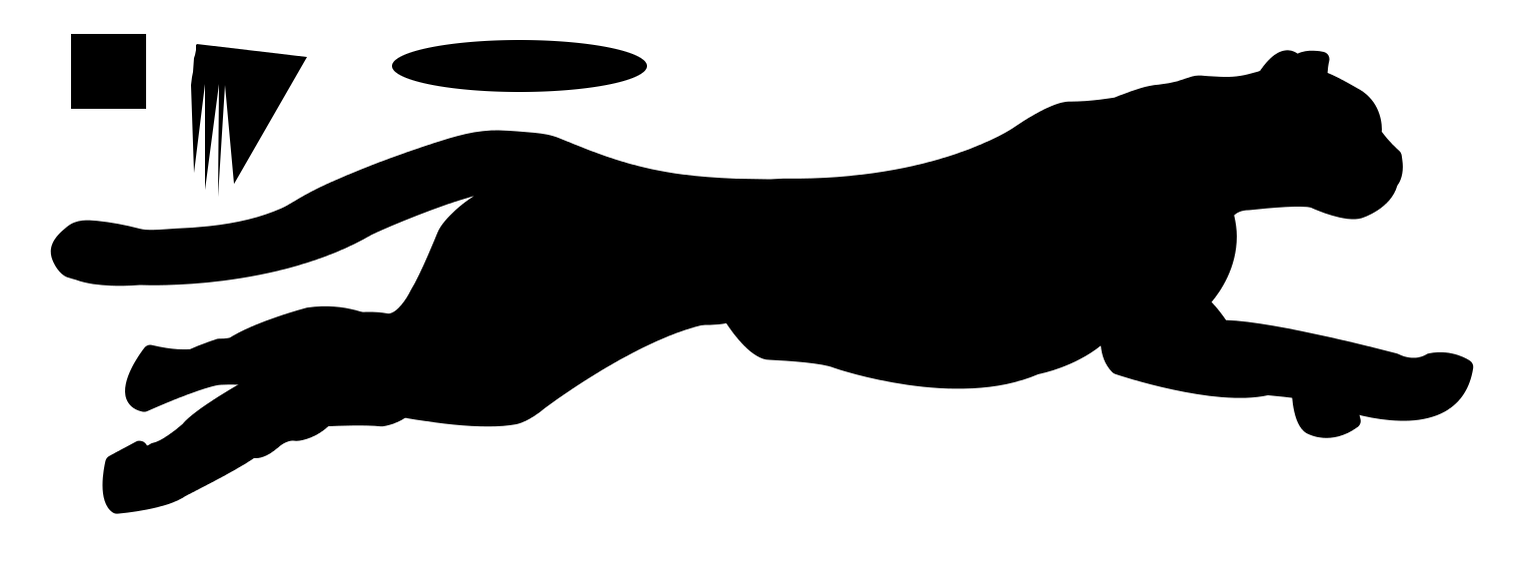
Calculation of the distance map is the simplest algorithm. It works on monochrome images where the pixel is either black or white. We consider one of the colors internal and the other external (as you like, the black pixel in this picture with the cheetah will be internal). Sometimes they are called background and foreground colors. For each “internal” pixel of the image, you need to find the closest “external” pixel to it and set the brightness value of this pixel as the Euclidean distanceto the nearest “external” pixel. That is, you need to calculate the distances to all the "external" pixels of the image and select the smallest of them. The resulting distance map is called Distance Field (DF), but so far it does not suit us. To get SDF (Signed DF), invert the image, repeat the algorithm, invert again and add to the previous result.
The intensity value does not need to be set exactly to the distance value: you can scale the “blurry” image depending on the needs. In particular, it is better to use a less blurry map for rendering clear contours, and for special effects such as a shadow or glow, it is better to increase the distance map:
Although ImageMagick is not the fastest and easiest way to create such a map, I think this is the best option, since ImageMagick is present on almost all operating systems and is often used by developers for pipelining sprites. It is enough to complete the script a bit and put the image generation on the stream.
Let's see how it works. If we simply take and apply the morphology operation to our image, we will not get the best result:
convert nosdf.png -morphology Distance Euclidean sdf.png
Malevich? No, just
-auto-level:convert nosdf.png -morphology Distance Euclidean -auto-level sdf.png
A flaw is immediately evident: a distance map is generated only from the outside. This is a consequence of the fact that the algorithm itself is also two-pass, we repeat the same for the negative:
convert nosdf.png -negate -morphology Distance Euclidean -auto-level sdf.png
Now the opposite situation - there is not enough card outside.
It remains to combine these two algorithms using an intermediate layer, tighten the contrast and get a furious script from the beginning of the post:
convert in.png -filter Jinc -resize 400% -threshold 30% \( +clone -negate -morphology Distance Euclidean -level 50%,-50% \) -morphology Distance Euclidean -compose Plus -composite -level 45%,55% -resize 25% out.png
Some explanations:
-resize 400%- increase the original image to eliminate the jagged edges. The algorithm works only for black-and-white images and I would like to at least somehow consider anti-aliasing. But I would always recommend having the original four times the size or more on hand. Valve, for example, uses a 4K image for demonstration, from which it receives a 64x64 SDF. This is of course already too much. I find the 8: 1 ratio acceptable. -level 45%,55%- you can adjust the degree of blurring of the distance map, by default it is already very vague. -filter Jincand -threshold 30%- experimentally, this filter and threshold provides the best fit to the original image. Under the spoiler, the script and source for those who want to check.Script to find the best PSNR metric
Naturally, there can be no one true option, but I left Jinc 30% as the most average option, giving an acceptable result.
Image:
Script:
Image:
Script:
#!/bin/sh
convert orig.png -resize 25% .orig-downscaled.png
convert orig.png -threshold 50% .orig-threshold.png
SIZE=$(identify orig.png| cut -d' ' -f3)
MAX=0.0
MAXRES=""
for filter in $(convert -list filter)
do
	for threshold in $(seq 1 99)
	do
		convert .orig-downscaled.png -filter $filter -resize $SIZE! -threshold $threshold% .tmp.png
		PSNR=$(compare -metric PSNR .orig-threshold.png .tmp.png /dev/null 2>&1)
		if [ "$(echo "$MAX < $PSNR" | bc -l)" = "1" ]
		then
			MAXRES="$PSNR $filter $threshold"
			echo $MAXRES
			MAX=$PSNR
		fi
		rm .tmp.png
	done
done
rm .orig-threshold.png .orig-downscaled.png
Well, if there is an original with a higher resolution, then you can do without a trick with increasing the scale and scale already only to a smaller side:
convert in.png -threshold 50% \( +clone -negate -morphology Distance Euclidean -level 50%,-50% \) -morphology Distance Euclidean -compose Plus -composite -level 45%,55% -filter Jinc -resize 10% out.png
Please note that the Jinc filter “moved” to the end of the chain, as it is intended to improve the quality of sampling while reducing the size of the map. Also, do not clean up
-threshold 50%- Euclidean does not work correctly for non-monochrome images. Some controversial issues .
Does it make sense to “stretch” the contrast?In general, theoretically, with increasing contrast, the delta of samples increases, from which antialiasing is then calculated using the hardware interpolation method. In short - you need to stretch, especially if you plan to display clear, smooth contours and effects like shadows are not so important. If the original card will not only stretch, but also shrink, you should not get carried away too much; otherwise, when you reduce the image size, the anti-aliasing, due to the blurry edges of the SDF, will deteriorate.
How does quality depend on the resolution of the SDF card? I tried to plot the PSNR versus map resolution and contrast. In general, the quality increases, but it still depends on the contrast of the card. You can evaluate the dependencies on the chart:
Here Scale is the scale as a percentage of the source, Level - how much the contrast was “stretched”. We can conclude that the dependence on the scale is not very linear, 30% will be a very compromise option, and the contrast rather strongly affects the quality of the contour.
How much does the size of the Euclidean filter affect quality ? Increasing the filter size gives an increase of 0.1 dB + - a penny, in my opinion this is not significant.
How much can you “shrink” the original image? It depends a lot on the shape. SDF does not like sharp corners, and such a smooth picture like the cheetah from the example feels great even on a miniature scale:
Implementing a Fast C ++ Algorithm
The algorithm is simple, but its “forehead” implementation will work for hours: in fact, you need to scan the entire image for each pixel. O (N ^ 2) does not suit us at all. But smart people already thought and came up with an algorithm for accurate (!) DF calculation, which works for O (N). It remains to extend the task to SDF, which is quite simple (see the previous example).
The bottom line. Instead of counting the distance for each pixel, we will perform two consecutive passes through the image, simply incrementing the distance under certain conditions. This is reminiscent of the fast Box-Blur algorithm. Matan can be gleaned from [2], but I will try to explain on the fingers.
I will call the pixel p the element of the array N * M composed of the original image. A pixel is the following structure:
{
    x, y - это покоординатное расстояние
    f - квадрат Евклидова расстояния
}
As you can see, there is nothing about brightness, etc. - it is not necessary. The array is formed as follows:
If the pixel of the source image is light, then
x = y = 9999
f = 9999 * 9999
If the pixel in the original image is dark, then
x = y = f = 0
Each pixel has 8 neighbors, we number them in this way:
2 3 4
1 p 5
8 7 6
Next, we introduce two auxiliary functions. The function h is needed to calculate the Euclidean distance between the pixel and the neighbor, the function G is needed to calculate the new distance value between the components.
h(p, q) {
    if q - сосед 1 или 5 {return 2 * q.x + 1}
    if q - сосед 3 или 7 {return 2 * q.y + 1}
    в остальных случаях {return 2 * (q.x + q.y + 1)}
}
G(p, q) {
    if q - сосед 1 или 5 {return (1, 0)}
    if q - сосед 3 или 7 {return (0, 1)}
    в остальных случаях {return (1, 1)}
}
First pass . This passage is performed in direct order (from the upper left corner of the image to the lower right). Pseudocode:
для каждого пикселя p изображения {
    для каждого соседа q от 1 до 4 {
        if (h(p, q) + q.f < p.f) {
            p.f = h(p, q) + q.f
            (p.x, p.y) = (q.x + q.y) + G(p, q)
        }
    }
}
Second pass . This pass is performed in the reverse order (from the lower right corner of the image to the upper left). Pseudocode:
для каждого пикселя p изображения {
    для каждого соседа q от 5 до 8 {
        if (h(p, q) + q.f < p.f) {
            p.f = h(p, q) + q.f
            (p.x, p.y) = (q.x + q.y) + G(p, q)
        }
    }
}
The algorithm needs to be repeated for the negative of the original image. Then, for the two received cards, you need to make the final distance calculation and subtraction to combine the two DF cards into one SDF:
d1 = sqrt(p1.f + 1);
d2 = sqrt(p2.f + 1);
d = d1 - d2;
Initially, we kept the Euclidean distance square in the structure, so we need to grind the root. Why you need to add one - don’t ask, the result is empirical and without it it turns out crooked :) The final SDF card is the result of subtracting the second from the first, then you need to scale the value as you like.
In my opinion, even an attempt to explain how it works on the fingers seems very confusing, so I will give the source code in C ++. As an input image, I used QImage from Qt, so as not to spoil the visibility of the process. The source is based on the source [3], but there are bugs there.
Source code
#include
#include
#include
struct Point
{
    short dx, dy;
    int f;
};
struct Grid
{
    int w, h;
    Point *grid;
};
Point pointInside = { 0, 0, 0 };
Point pointEmpty = { 9999, 9999, 9999*9999 };
Grid grid[2];
static inline Point Get(Grid &g, int x, int y)
{
    return g.grid[y * (g.w + 2) + x];
}
static inline void Put(Grid &g, int x, int y, const Point &p)
{
    g.grid[y * (g.w + 2) + x] = p;
}
static inline void Compare(Grid &g, Point &p, int x, int y, int offsetx, int offsety)
{
    int add;
    Point other = Get(g, x + offsetx, y + offsety);
    if(offsety == 0) {
        add = 2 * other.dx + 1;
    }
    else if(offsetx == 0) {
        add = 2 * other.dy + 1;
    }
    else {
        add = 2 * (other.dy + other.dx + 1);
    }
    other.f += add;
    if (other.f < p.f)
    {
        p.f = other.f;
        if(offsety == 0) {
            p.dx = other.dx + 1;
            p.dy = other.dy;
        }
        else if(offsetx == 0) {
            p.dy = other.dy + 1;
            p.dx = other.dx;
        }
        else {
            p.dy = other.dy + 1;
            p.dx = other.dx + 1;
        }
    }
}
static void GenerateSDF(Grid &g)
{
    for (int y = 1; y <= g.h; y++)
    {
        for (int x = 1; x <= g.w; x++)
        {
            Point p = Get(g, x, y);
            Compare(g, p, x, y, -1,  0);
            Compare(g, p, x, y,  0, -1);
            Compare(g, p, x, y, -1, -1);
            Compare(g, p, x, y,  1, -1);
            Put(g, x, y, p);
        }
    }
    for(int y = g.h; y > 0; y--)
    {
        for(int x = g.w; x > 0; x--)
        {
            Point p = Get(g, x, y);
            Compare(g, p, x, y,  1,  0);
            Compare(g, p, x, y,  0,  1);
            Compare(g, p, x, y, -1,  1);
            Compare(g, p, x, y,  1,  1);
            Put(g, x, y, p);
        }
    }
}
static void dfcalculate(QImage *img, int distanceFieldScale)
{
    int x, y;
    int w = img->width(), h = img->height();
    grid[0].w = grid[1].w = w;
    grid[0].h = grid[1].h = h;
    grid[0].grid = (Point*)malloc(sizeof(Point) * (w + 2) * (h + 2));
    grid[1].grid = (Point*)malloc(sizeof(Point) * (w + 2) * (h + 2));
    /* create 1-pixel gap */
    for(x = 0; x < w + 2; x++)
    {
        Put(grid[0], x, 0, pointInside);
        Put(grid[1], x, 0, pointEmpty);
    }
    for(y = 1; y <= h; y++)
    {
        Put(grid[0], 0, y, pointInside);
        Put(grid[1], 0, y, pointEmpty);
        for(x = 1; x <= w; x++)
        {
            if(qGreen(img->pixel(x - 1, y - 1)) > 128)
            {
                Put(grid[0], x, y, pointEmpty);
                Put(grid[1], x, y, pointInside);
            }
            else
            {
                Put(grid[0], x, y, pointInside);
                Put(grid[1], x, y, pointEmpty);
            }
        }
        Put(grid[0], w + 1, y, pointInside);
        Put(grid[1], w + 1, y, pointEmpty);
    }
    for(x = 0; x < w + 2; x++)
    {
        Put(grid[0], x, h + 1, pointInside);
        Put(grid[1], x, h + 1, pointEmpty);
    }
    GenerateSDF(grid[0]);
    GenerateSDF(grid[1]);
    for(y = 1; y <= h; y++)
        for(x = 1; x <= w; x++)
        {
            double dist1 = sqrt((double)(Get(grid[0], x, y).f + 1));
            double dist2 = sqrt((double)(Get(grid[1], x, y).f + 1));
            double dist = dist1 - dist2;
            // Clamp and scale
            int c = dist * 64 / distanceFieldScale + 128;
            if(c < 0) c = 0;
            if(c > 255) c = 255;
            img->setPixel(x - 1, y - 1, qRgb(c,c,c));
        }
    free(grid[0].grid);
    free(grid[1].grid);
}
A trick is used here: since both passes use a “window” of 1 pixel width, I add a single-pixel border around the original image to avoid checking the borders. For negative, the border also needs to be changed to the opposite value, which was not taken into account in [3].
A complete working algorithm can be found in the open source raster font generator UBFG . Example result:
Shaderim
The idea of the inverse transformation (from SDF to raster contour) is based on increasing the contrast to such an extent that blurry edges will not be visible. By changing the contrast of the SDF, you can get various effects, as well as adjust the quality of anti-aliasing of the image. As an example, take the source:
This is also an SDF, just very compressed and reduced in size. Increase it by 16 times:
Now, to get a beautiful outline, increase the contrast. I used GIMP for these purposes:
To see the result of using SDF in real time, shaders are indispensable. The simplest alpha test can also be used, but it cuts anti-aliasing at its root. However, the shader used is just a couple of instructions and does not actually affect performance. Moreover, considering that shaders are cheap now, and memory / cache are expensive, you can get good acceleration due to saving video memory.
Now let's see how this business can be used in OpenGL. All examples will be given as pure GLSL source code. You can try it in any shader editor. I tested all the examples in the Kick.js editor , as this is the only editor that allows you to load your textures.
The simplest quick option
precision highp float;
uniform sampler2D tex;
const float contrast = 40.;
void main(void)
{
	vec3 c = texture2D(tex,gl_FragCoord.xy/vec2(256., 128.)*.3).xxx;
	gl_FragColor = vec4((c-0.5)*contrast,1.0);
}
Here we simply draw the contrast relative to the average value (0.5). The strength of the contrast should vary depending on the scale of the texture and the smear of the DF map - the parameter is selected experimentally and set through uniform with a scale factor.
You can slightly improve the quality with a filter
smoothstep:precision highp float;
uniform sampler2D tex;
const float threshold = .01;
void main(void)
{
vec3 c = texture2D(tex,gl_FragCoord.xy/vec2(256., 128.)*.3).xxx;
vec3 res = smoothstep(.5-threshold, .5+threshold, c);
gl_FragColor = vec4(res,1.0);
}
Here the threshold also needs to be selected.
smoothstepa bit slower on older graphics cards and phones.Outline effect
To get this effect, you need to take two thresholds and invert the color:
precision highp float;
uniform sampler2D tex;
const float contrast = 20.;
void main(void)
{
	vec3 c = texture2D(tex,gl_FragCoord.xy/vec2(256., 128.)*.35).xxx;
	vec3 c1 = (c-.45) * contrast;
	vec3 c2 = 1.-(c-.5) * contrast;
	vec3 res = mix(c1, c2, (c-.5)*contrast);
	gl_FragColor = vec4(res,1.0);
}
Result:
Glow and shadow effect
A little more chemistry over the previous example - and we get the glow effect:
precision highp float;
uniform sampler2D tex;
const float contrast = 20.;
const float glow = 2.;
void main(void)
{
    vec3 c = texture2D(tex,gl_FragCoord.xy/vec2(256., 128.)*.35).xxx;
    vec3 c1 = clamp((c-.5)*contrast,0.,1.);
    vec3 c2 = clamp(1.-(c-.5)/glow, 0., 1.);
    vec3 res = 1.-mix(c1, c2, (c-.5)*contrast);
    gl_FragColor = vec4(res,1.0);
}
To get a shadow, you need to take a color for glow with an offset:
precision highp float;
uniform sampler2D tex;
const float contrast = 20.;
const float glow = 2.;
void main(void)
{
    vec3 c = texture2D(tex,gl_FragCoord.xy/vec2(256., 128.)*.35).xxx;
    vec3 gc = texture2D(tex,gl_FragCoord.xy/vec2(256., 128.)*.35 + vec2(-0.02,0.02)).xxx;
    vec3 c1 = clamp((c-.5)*contrast,0.,1.);
    vec3 c2 = clamp(1.-(gc-.5)/glow, 0., 1.);
    vec3 res = 1.-mix(c1, c2, (c-.5)*contrast);
    gl_FragColor = vec4(res,1.0);
}
Result:
The result may not seem so hot, but this is because I used a map too small:
References
[1] Improved Alpha-Tested Magnification for Vector Textures and Special Effects is the same article from Valve.
[2] Frank Y. Shih, Yi-Ta Wu. Fast Euclidean distance transformation in two scans using a 3x3 neighborhood - Chinese? No, just a University of New Jersey.
[3] www.codersnotes.com/notes/signed-distance-fields - this is also a fairly fast algorithm, but unfortunately its author made several errors and multiplication is present, which is slightly slower than the algorithm presented in this article.
[4] contourtextures.wikidot.com- Another implementation of the SDF calculation, but its advantage is that it can take into account the smoothing of the edges to determine the nearest points. Nothing is said about performance, but it’s good when there is no way to get a high-resolution original (on the other hand, you can just do the upscale trick). If you had experience using it, unsubscribe in the comments.
[5] gpuhacks.wordpress.com/2013/07/08/signed-distance-field-rendering-of-color-bit-planes - a method of rendering color vector images (suitable for a small number of colors).
[6] distance.sourceforge.net is an interesting resource on which various SDF calculation algorithms are compared.
upd. Thanks to the remark by Bas1l, the algorithm is still not entirely accurate and may give errors in calculating the distance to the nearest neighbors due to an error in the proof. In this paper we presented an improved version of the algorithm.
upd2 . From user achkasov a comment regarding shaders. In the event of sudden transitions, fusions and uneven anti-aliasing may appear on the SDF card. More information about the effect and how to deal with it: iquilezles.org/www/articles/distance/distance.htm
Changing the shader, we get a significant improvement in the area, ahem, tail:
GLSL Code
precision highp float;
uniform sampler2D tex;
const float contrast = 2.;
float f(vec2 p)
{
	return texture2D(tex,p).x - 0.5;
}
vec2 grad(vec2 p)
{
    vec2 h = vec2( 4./256.0, 0.0 );
    return vec2( f(p+h.xy) - f(p-h.xy),
                 f(p+h.yx) - f(p-h.yx) )/(2.0*h.x);
}
void main(void)
{
	vec2 p = gl_FragCoord.xy/vec2(256., 128.)*.35;
    //float c = texture2D(tex,p).x;
    float v = f(p);
    vec2  g = grad(p);
    float c = (v)/length(g);
    float res = c * 300.;
    gl_FragColor = vec4(res,res,res, 1.0);
}