Programming a microwave or controller 40 years ago
Hi, recently a piece of iron fell into my hands quite by accident:
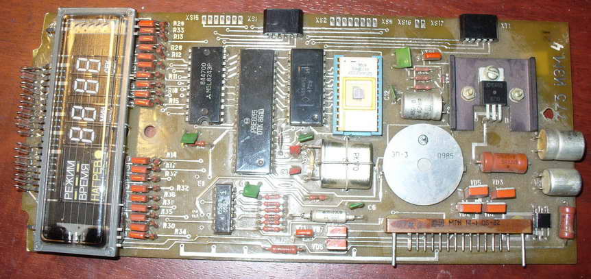
Well, a piece of iron and a piece of iron, I thought ... There is a microcontroller PBE035, an IO m5l8243p expander, IR12 between the RF5 and the controller, and there is somewhere else LN1 hanging out. I immediately liked the good rare 2Kb RF5 ROM in a socket in gold. I think I’ll take it off, and the rest is boldly scrapped, since the whole board is covered with varnish for the most fun. And then it all became interesting, but what is it all about?
It turned out that this is a control board from a Soviet microwave type Electronics 23 (aka BUVI-2 aka Fairy aka Dneprjanka). Even the device diagram was quickly found on the Internet: http://www.elremont.ru/small_rbt/bt_rem32.php Now, when it became clear what it was, one hand confidently reached for the trash, and the other accidentally knocked in Google "PBE035" and ... And I became interested and looked carefully at the board. If there is a controller, then you can write programs for it. Still directly on the board there is some kind of screen (4 digits) where you can display all kinds of swearing curses (BABA, SISI, well, you understand). Also there is still a piezoelectric element, which means you can squeak. Everything else can be connected 4x4 keyboard. It's just some kind of devboard it turns out, I was delighted!
As already mentioned, the board has a PBE035 controller. In Russia, it is better known by the name KR1816BE35, but in general, it is the great and terrible Intel 8035 MSC-48 series . The first copies began to be produced in 1976, that is, about 40 years ago. The controller does not have its own memory for programs, so it communicates via ROM with the ROM, from where it reads the instructions for execution. But there are 64 bytes of RAM, of which about 32 bytes can be used as you like, and the rest are for registers and the stack. There is a timer, there is an interrupt from the timer, there is an external interrupt, there is a priority system. In short, a normal old-school controller, not even bold PICs. What the Bolsheviks have been waiting for so long. I immediately wanted to code something for him.
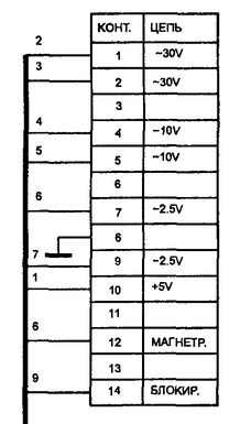
But first, one difficulty was to be solved, namely, connecting the board. As can be seen from the diagram, just + 5V is required to power the digital part, but 2.5V and 30V of alternating voltage are needed to power the indicator.
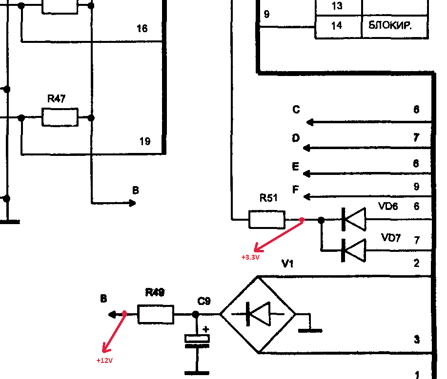
By the way, about the indicator - it's a lamp! Yes, a warm tube lamp, and not some pop-up LEDs there. And like a lamp, it has a cathode anode and a grid. This type of indicator is called a luminescent-vacuum indicator. After thinking a little over the circuit, I saw that 30V changes go to the diode bridge, which means they are straightened. And even 2.5V also goes to the diodes and after them to the grid, which means they also straighten. So, you can try to connect the board to a constant voltage. Instead of 30V, I applied 12V, instead of 2.5V, I applied 3.3V from a standard ATX format power supply. To do this, soldered wiring to the board. It turned out like this:
But turning on the board, at first I was disappointed. Some segments on the display did not light. At first I thought that 12 volts is not enough, but then carefully examining the board I found nepropay in two places next to the indicator. I called, I disappeared. The board started up, numbers appeared on the screen to set the time and select the program mode. So, I wanted to throw it away, but in the end I fixed it. It’s time to fry.
I used the free cross-platform assembler Asm48. It's cool that there is a version for MacOS, apparently the authors are not deprived of a sense of humor, at least I appreciated. Well, it means downloading the assembler, everything is simple: ASM48 <filename.asm> The first thing I did was “blink the LED”, but instead of the LED, I pulled the leg of the speaker (piezoelectric element) in an endless loop with a delay. The speaker is connected to port 1, the most significant bit:
After compiling the program and stitching it on the programmer in ROM 2716, I launch the board and hear periodic clicks with an interval of about a second. Works! Now I had to deal with the screen. According to the diagram, the “mask” of the ABCDEFG symbol is connected to port 1. Moreover, the signal is inverted, that is, when 1 - the stick is off, when 0 - is on. In order to set the mask of the letter “H” we will look at the picture:
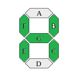
We start bypassing the letter from G to A, since here the reverse order of the bits: G is filled, then 1; F is painted over, then 1; E painted over, then 1; D is not painted over, then 0 and so on. The result is: 1110110b. We remember that the signals are inverted, so we need to invert the mask itself: not 1110110b = 0001001b. Or 9h. Sending this number to port 1 we will set the mask for the letter. More difficult to select a character. Here the dynamic indication is applied. In short, the essence boils down to the fact that we constantly need to set the mask, light the first character, set the mask, light the second character, and so on. The second port is responsible for resolving the glow of the symbol, which, with the help of the m5l8243p microchip, has been expanded to 4 four-bit ports. To access these ports, use the MOVD command ., and the ports themselves are numbers P4, P5, P6, P7. P4, according to the authors, is responsible for scanning the keyboard, but P5 just sets one of the four characters to display.
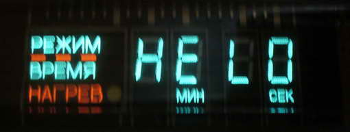
At first I tried to make a dynamic indication in the main loop of the program, but then I used a timer for this. And in the main cycle of the program, the indicator buffer changes, displaying the inscriptions “HELO” and “2014” with a frequency of 1 second
A short video demonstration of the device:
An inquisitive habrayuzer probably noticed a bug at the end of the video, when instead of HELO, not quite what was needed was displayed. I noticed him too, yes. And all because when in the main program there is a transfer to the display buffer, I forgot to stop the timer. Before call copy_buf you need to do DIS TCNTI and after EN TCNTI. So that!
Now it only remains to play on the device “a Christmas tree was born in the forest” and I will consider the mission successfully completed. Good to all!
1) MCS-48 AND UPI-41 ASSEMBLER LANGUAGE MANUAL 1976
2) 2 volume of the Shakhnov Directory (Microprocessors and microprocessor sets of integrated circuits)
3) Stashin V.V. et al. - Design of digital devices on single-chip microcontrollers
4) Sign-synthesizing indicators: Reference / Ed. V.P. Balashova
5) Bystrov Yu.A. One hundred charts with indicators
Well, a piece of iron and a piece of iron, I thought ... There is a microcontroller PBE035, an IO m5l8243p expander, IR12 between the RF5 and the controller, and there is somewhere else LN1 hanging out. I immediately liked the good rare 2Kb RF5 ROM in a socket in gold. I think I’ll take it off, and the rest is boldly scrapped, since the whole board is covered with varnish for the most fun. And then it all became interesting, but what is it all about?
It turned out that this is a control board from a Soviet microwave type Electronics 23 (aka BUVI-2 aka Fairy aka Dneprjanka). Even the device diagram was quickly found on the Internet: http://www.elremont.ru/small_rbt/bt_rem32.php Now, when it became clear what it was, one hand confidently reached for the trash, and the other accidentally knocked in Google "PBE035" and ... And I became interested and looked carefully at the board. If there is a controller, then you can write programs for it. Still directly on the board there is some kind of screen (4 digits) where you can display all kinds of swearing curses (BABA, SISI, well, you understand). Also there is still a piezoelectric element, which means you can squeak. Everything else can be connected 4x4 keyboard. It's just some kind of devboard it turns out, I was delighted!
As already mentioned, the board has a PBE035 controller. In Russia, it is better known by the name KR1816BE35, but in general, it is the great and terrible Intel 8035 MSC-48 series . The first copies began to be produced in 1976, that is, about 40 years ago. The controller does not have its own memory for programs, so it communicates via ROM with the ROM, from where it reads the instructions for execution. But there are 64 bytes of RAM, of which about 32 bytes can be used as you like, and the rest are for registers and the stack. There is a timer, there is an interrupt from the timer, there is an external interrupt, there is a priority system. In short, a normal old-school controller, not even bold PICs. What the Bolsheviks have been waiting for so long. I immediately wanted to code something for him.
But first, one difficulty was to be solved, namely, connecting the board. As can be seen from the diagram, just + 5V is required to power the digital part, but 2.5V and 30V of alternating voltage are needed to power the indicator.
By the way, about the indicator - it's a lamp! Yes, a warm tube lamp, and not some pop-up LEDs there. And like a lamp, it has a cathode anode and a grid. This type of indicator is called a luminescent-vacuum indicator. After thinking a little over the circuit, I saw that 30V changes go to the diode bridge, which means they are straightened. And even 2.5V also goes to the diodes and after them to the grid, which means they also straighten. So, you can try to connect the board to a constant voltage. Instead of 30V, I applied 12V, instead of 2.5V, I applied 3.3V from a standard ATX format power supply. To do this, soldered wiring to the board. It turned out like this:
But turning on the board, at first I was disappointed. Some segments on the display did not light. At first I thought that 12 volts is not enough, but then carefully examining the board I found nepropay in two places next to the indicator. I called, I disappeared. The board started up, numbers appeared on the screen to set the time and select the program mode. So, I wanted to throw it away, but in the end I fixed it. It’s time to fry.
I used the free cross-platform assembler Asm48. It's cool that there is a version for MacOS, apparently the authors are not deprived of a sense of humor, at least I appreciated. Well, it means downloading the assembler, everything is simple: ASM48 <filename.asm> The first thing I did was “blink the LED”, but instead of the LED, I pulled the leg of the speaker (piezoelectric element) in an endless loop with a delay. The speaker is connected to port 1, the most significant bit:
jmp main
nop
nop
nop
nop
nop
nop
main:
	movr6,#0                                  ; в регистре r6 - 0 или 80hforever:
	mova,r6                                    ; пересылаем из регистра в ALUxrla,#080h                                ; a = axor 80houtlp1,a                                    ; выводим в порт 1
	movr6,a                                    ; сохраняем значение в r6callonesec                              ; секундная задержка
	jmpforever                                ; бесконечный цикл
;---PROCEDURES
;;;;;;;;
delay100:
 	movr1,#84
loopex:	movr2,#236
loopin:	djnzr2,loopindjnzr1,loopexmovr3,#4
loopad: djnzr3,loopadret
;;;;;;;;
onesec:
	movr4,#10
loop_d: calldelay100djnzr4,loop_dret
After compiling the program and stitching it on the programmer in ROM 2716, I launch the board and hear periodic clicks with an interval of about a second. Works! Now I had to deal with the screen. According to the diagram, the “mask” of the ABCDEFG symbol is connected to port 1. Moreover, the signal is inverted, that is, when 1 - the stick is off, when 0 - is on. In order to set the mask of the letter “H” we will look at the picture:
We start bypassing the letter from G to A, since here the reverse order of the bits: G is filled, then 1; F is painted over, then 1; E painted over, then 1; D is not painted over, then 0 and so on. The result is: 1110110b. We remember that the signals are inverted, so we need to invert the mask itself: not 1110110b = 0001001b. Or 9h. Sending this number to port 1 we will set the mask for the letter. More difficult to select a character. Here the dynamic indication is applied. In short, the essence boils down to the fact that we constantly need to set the mask, light the first character, set the mask, light the second character, and so on. The second port is responsible for resolving the glow of the symbol, which, with the help of the m5l8243p microchip, has been expanded to 4 four-bit ports. To access these ports, use the MOVD command ., and the ports themselves are numbers P4, P5, P6, P7. P4, according to the authors, is responsible for scanning the keyboard, but P5 just sets one of the four characters to display.
At first I tried to make a dynamic indication in the main loop of the program, but then I used a timer for this. And in the main cycle of the program, the indicator buffer changes, displaying the inscriptions “HELO” and “2014” with a frequency of 1 second
Program source
;DATA
	.equ disp_buf, 030h			; 4 bytes buffer
;;;  reset vector
	.org	0
	dis 	i			; disable interrupts
	jmp	main
;;;  external interrupt vector--trap
	.org	3
	jmp	$			; nop
;;;  timer interrupt vector
	.org	7
	sel 	rb1
	mov a,#0d5h
	mov t,a
	mov	a,#00FH
	orld	p5,a
	mov	a,disp_buf-1
	add	a,r5
	mov	r0,a
	mov 	a,@r0
	outl 	p1,a
	mov	a,r4
	movd	p5,a
	rl	a
	mov	r4,a
	djnz	r5,exit_tmr
	mov	r4,#0feh
	mov	r5,4
exit_tmr:
	selrb0mova,#0d8hmovt,a
;	strttretr
;MAINmain:
	;initializedistcnti			; turnoffcountermovr1,#0
	movr5,#0
	callcopy_bufselrb1			; timervariablesmovr4,#0feh		; 1110h - CTpositionmovr5,4			; R5 = bufoffsetselrb0mova,#0e5hmovt,astrttentcntimova,#0ffhmovdp6,amain_loop:
	callonesecmova,r5xrla,#4
	movr5,amovr1,acallcopy_bufjmpmain_loopmsg_table:
	.db #0c0h		;O
	.db #0c7h		;L
	.db #086h		;E
	.db #089h		;H
	.db #099h		;4
	.db #0f9h		;1
	.db #0c0h		;0
	.db #0a4h		;2
;;;;;;;;
delay100:
 	movr6,#84
loopex:	movr2,#236
loopin:	djnzr2,loopindjnzr6,loopexmovr6,#4
loopad: djnzr6,loopadret
;;;;;;;;
onesec:
	movr3,#10
loop_d: calldelay100djnzr3,loop_dret
;;;;;;;;
;copyfrommsg_tabletodisplaybuffer 4 bytes
; R1 = msg_tableoffset
;;;;;;;;
copy_buf:
	movr0,disp_bufmovr2,4
copy_lp:
	mova,r1adda,#msg_tablemovpa,@amov @r0,aincr0incr1djnzr2,copy_lpret
A short video demonstration of the device:
An inquisitive habrayuzer probably noticed a bug at the end of the video, when instead of HELO, not quite what was needed was displayed. I noticed him too, yes. And all because when in the main program there is a transfer to the display buffer, I forgot to stop the timer. Before call copy_buf you need to do DIS TCNTI and after EN TCNTI. So that!
Now it only remains to play on the device “a Christmas tree was born in the forest” and I will consider the mission successfully completed. Good to all!
Literature:
1) MCS-48 AND UPI-41 ASSEMBLER LANGUAGE MANUAL 1976
2) 2 volume of the Shakhnov Directory (Microprocessors and microprocessor sets of integrated circuits)
3) Stashin V.V. et al. - Design of digital devices on single-chip microcontrollers
4) Sign-synthesizing indicators: Reference / Ed. V.P. Balashova
5) Bystrov Yu.A. One hundred charts with indicators