Modifying Turnigy 9x equipment
- Tutorial
Everyone who is interested in radio-controlled models knows Turnigy 9x equipment. This is practically a folk equipment of RU.
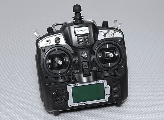
Affordable, there are many accessories and alternative firmware for it. For example, this is what my instance looks like:

It has an alternative firmware - er9x, added backlight, sticks are replaced with wide ones, a hinged stand is added at the back, a cable for flashing and editing settings from a PC is displayed in the battery compartment, powered by a 2S LiIon battery.
And everything would be fine in this equipment, because it is modular. You can put any module transmitter JR standard. And there is a sea of them - for almost any wallet and task. However, there are two configuration options - with a native Turnigy 9x radio module and no module at all.
The native module does not have its own antenna and is connected to the upper antenna on the transmitter body with an integral cable so that the module cannot be disconnected and it can only be replaced by biting off the antenna cable: The
native transmitter module is not sold separately, as hardware version without module also without antenna:
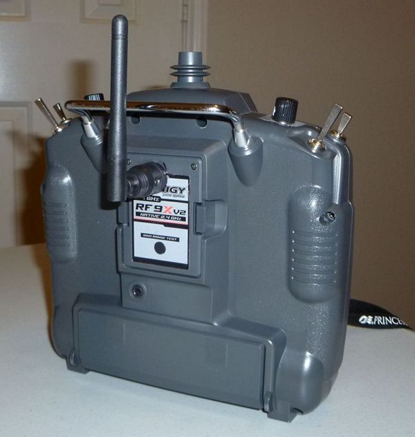
So to put it in the option without a module in the kit will fail. There are alterations in the network where the antenna is brought to the rear wall of the module, but using the transmitter in this version is terribly inconvenient - you won’t put it on the table, you can’t put the antenna in the backpack without risk:
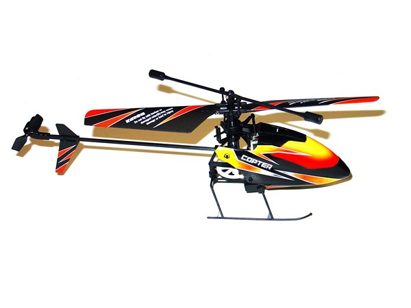
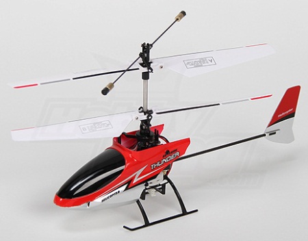
But the native module is good - it is compatible with a whole bunch of inexpensive 4 receivers , 6, 8 channels, and also compatible with micro-helicopters:
In general, I don’t want to refuse it. Well, we won’t. We will make this module fully replaceable.
We take out the module from the slot, unscrew the two screws and remove the back cover. Do not break the antenna cable!

Inside a sandwich of two boards, fixed with two hot-melt glue nozzles. Carefully remove the hot glue and solder the antenna. You need to solder quickly - the solder is lead free, you need to heat up strongly, and the tracks are thin. Now you can shake the electronics on the table.
Now we take a copper braid (desoldering wick) and richly impregnating it with a flux, carefully remove the solder from the comb connecting the boards. We disconnect the boards:
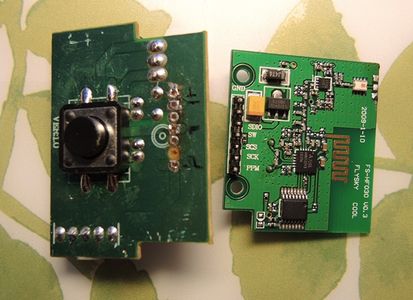
By the way, it is clearly visible that the module produces FlySky, from which Turnigy9x is copied :)
The large module contains a binding button and a linear stabilizer on the back. We will leave it in the box, and actually the transmitter will be moved inside the equipment case, the benefit of the place is full. There are many pins on the module, but we only need 4 of them: power, ground, PPM signal and button.
To do this, we disassemble the equipment case by unscrewing all the screws in a circle and gently disconnect the wiring harness connecting the halves of the case.
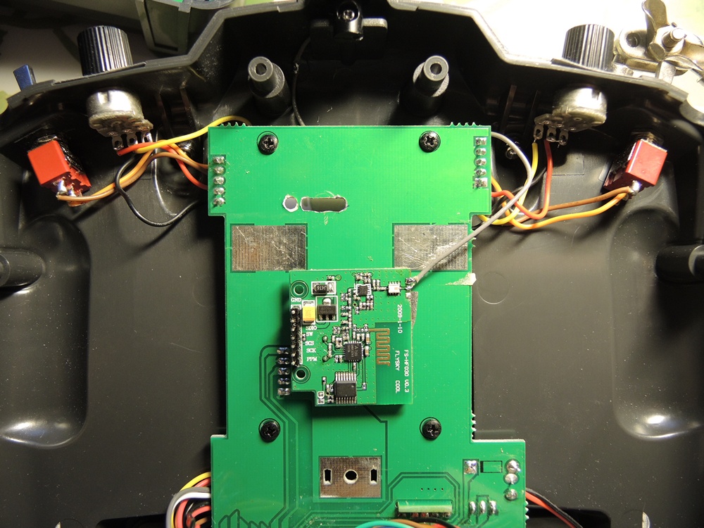
On the back half, we fasten the two-sided porous adhesive tape with the transmitter board and solder the antenna cable into place. And in the board we drill three holes and with a file we align the edges to the size of the PBS-4 connector:

On the reverse side, the hole looks like this:
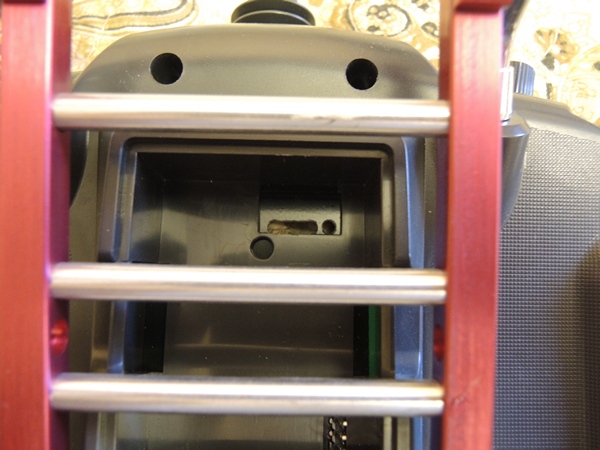
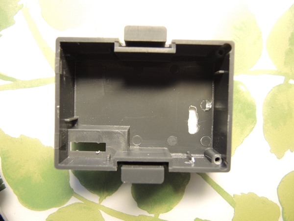
Then we insert the empty module case and mark the hole on the inside with a marker, then remove the case and cut the counter hole in it:
Now insert the PBS-4 connector into the hole so that it is flush with the bottom of the niche on the back side:
Fix it with superglue and after drying for strength, you can add hot glue.
We connect the connector and the module with the wiring harnesses:

Now we insert the empty housing again and insert the PLS-4 plug through the hole into the already glued connector, gently fasten the plug with superglue in the module housing, wait until it dries and also fix the result with hot-melt adhesive. We solder the wiring to the board and fix it with the same hot glue as was done by the Chinese.
We close and screw the lid, assemble the equipment case.
Voila, we have a native module that you can take out and put any other in its place. The quality of communication does not suffer at the same time - the entire RF part is inside, and through the connector we drive only PPM and the power of the radio module.
That is, for the same money we get full-fledged modular equipment.
Affordable, there are many accessories and alternative firmware for it. For example, this is what my instance looks like:
It has an alternative firmware - er9x, added backlight, sticks are replaced with wide ones, a hinged stand is added at the back, a cable for flashing and editing settings from a PC is displayed in the battery compartment, powered by a 2S LiIon battery.
And everything would be fine in this equipment, because it is modular. You can put any module transmitter JR standard. And there is a sea of them - for almost any wallet and task. However, there are two configuration options - with a native Turnigy 9x radio module and no module at all.
The native module does not have its own antenna and is connected to the upper antenna on the transmitter body with an integral cable so that the module cannot be disconnected and it can only be replaced by biting off the antenna cable: The
native transmitter module is not sold separately, as hardware version without module also without antenna:
So to put it in the option without a module in the kit will fail. There are alterations in the network where the antenna is brought to the rear wall of the module, but using the transmitter in this version is terribly inconvenient - you won’t put it on the table, you can’t put the antenna in the backpack without risk:
But the native module is good - it is compatible with a whole bunch of inexpensive 4 receivers , 6, 8 channels, and also compatible with micro-helicopters:
In general, I don’t want to refuse it. Well, we won’t. We will make this module fully replaceable.
Disassemble
We take out the module from the slot, unscrew the two screws and remove the back cover. Do not break the antenna cable!
Inside a sandwich of two boards, fixed with two hot-melt glue nozzles. Carefully remove the hot glue and solder the antenna. You need to solder quickly - the solder is lead free, you need to heat up strongly, and the tracks are thin. Now you can shake the electronics on the table.
Now we take a copper braid (desoldering wick) and richly impregnating it with a flux, carefully remove the solder from the comb connecting the boards. We disconnect the boards:
By the way, it is clearly visible that the module produces FlySky, from which Turnigy9x is copied :)
The large module contains a binding button and a linear stabilizer on the back. We will leave it in the box, and actually the transmitter will be moved inside the equipment case, the benefit of the place is full. There are many pins on the module, but we only need 4 of them: power, ground, PPM signal and button.
To do this, we disassemble the equipment case by unscrewing all the screws in a circle and gently disconnect the wiring harness connecting the halves of the case.
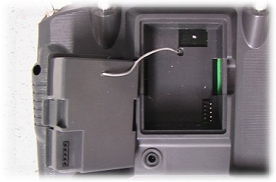
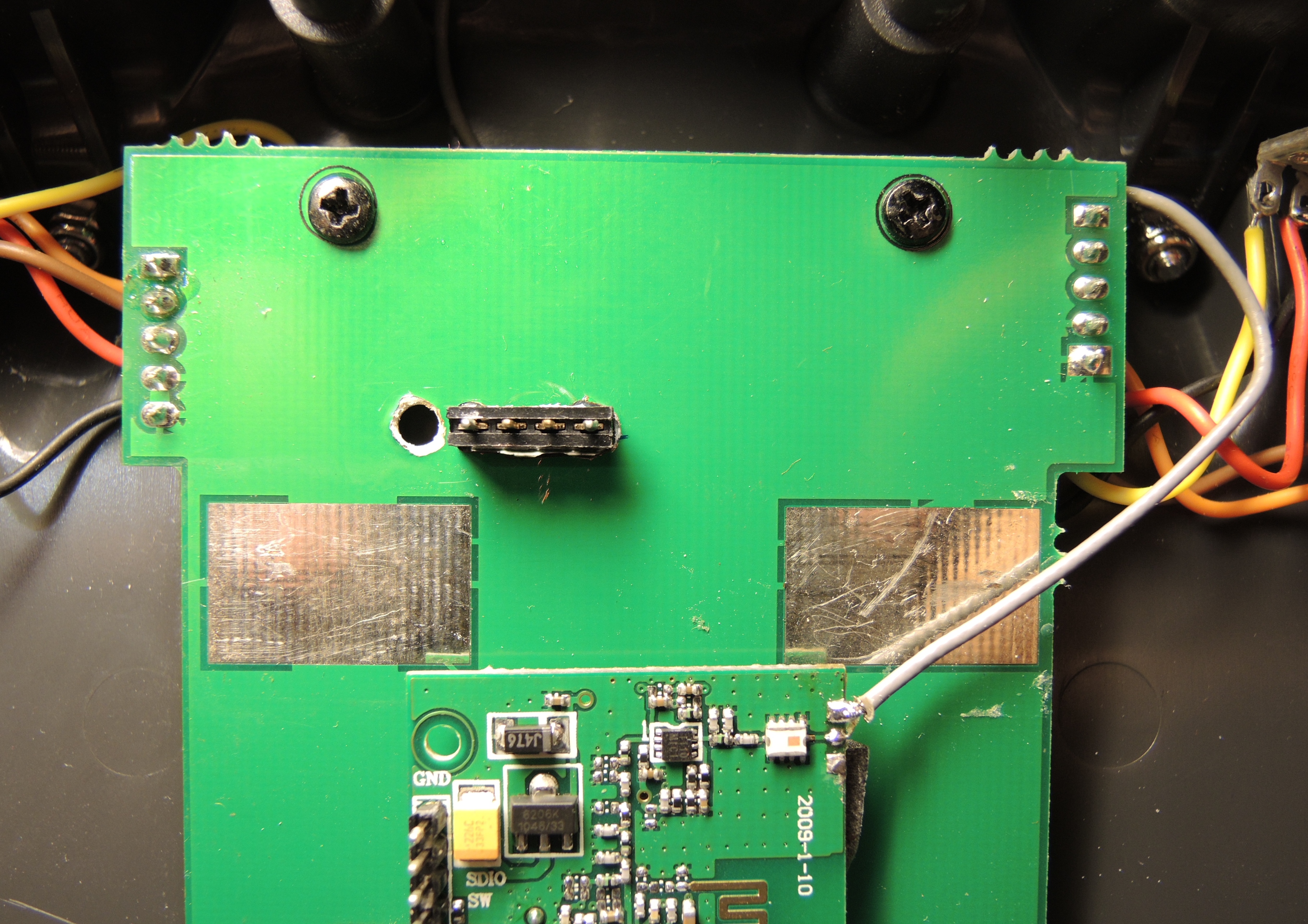
On the back half, we fasten the two-sided porous adhesive tape with the transmitter board and solder the antenna cable into place. And in the board we drill three holes and with a file we align the edges to the size of the PBS-4 connector:
On the reverse side, the hole looks like this:
Then we insert the empty module case and mark the hole on the inside with a marker, then remove the case and cut the counter hole in it:
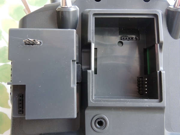
Now insert the PBS-4 connector into the hole so that it is flush with the bottom of the niche on the back side:
Fix it with superglue and after drying for strength, you can add hot glue.
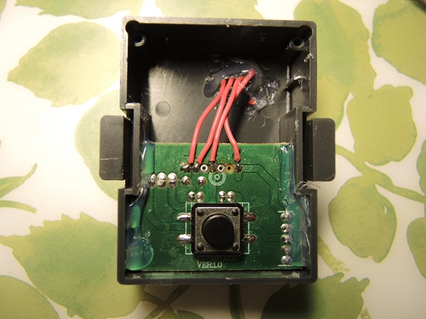
We connect the connector and the module with the wiring harnesses:
Now we insert the empty housing again and insert the PLS-4 plug through the hole into the already glued connector, gently fasten the plug with superglue in the module housing, wait until it dries and also fix the result with hot-melt adhesive. We solder the wiring to the board and fix it with the same hot glue as was done by the Chinese.
We close and screw the lid, assemble the equipment case.
Voila, we have a native module that you can take out and put any other in its place. The quality of communication does not suffer at the same time - the entire RF part is inside, and through the connector we drive only PPM and the power of the radio module.
That is, for the same money we get full-fledged modular equipment.