Modding Switching Power Supply ARPV-SC1E-12005T
Somehow I bought this power supply, lay around for a long time and decided to adapt it, but the weekend 12V did not suit my needs. It was decided to redo it.
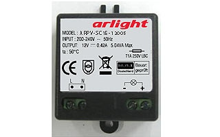
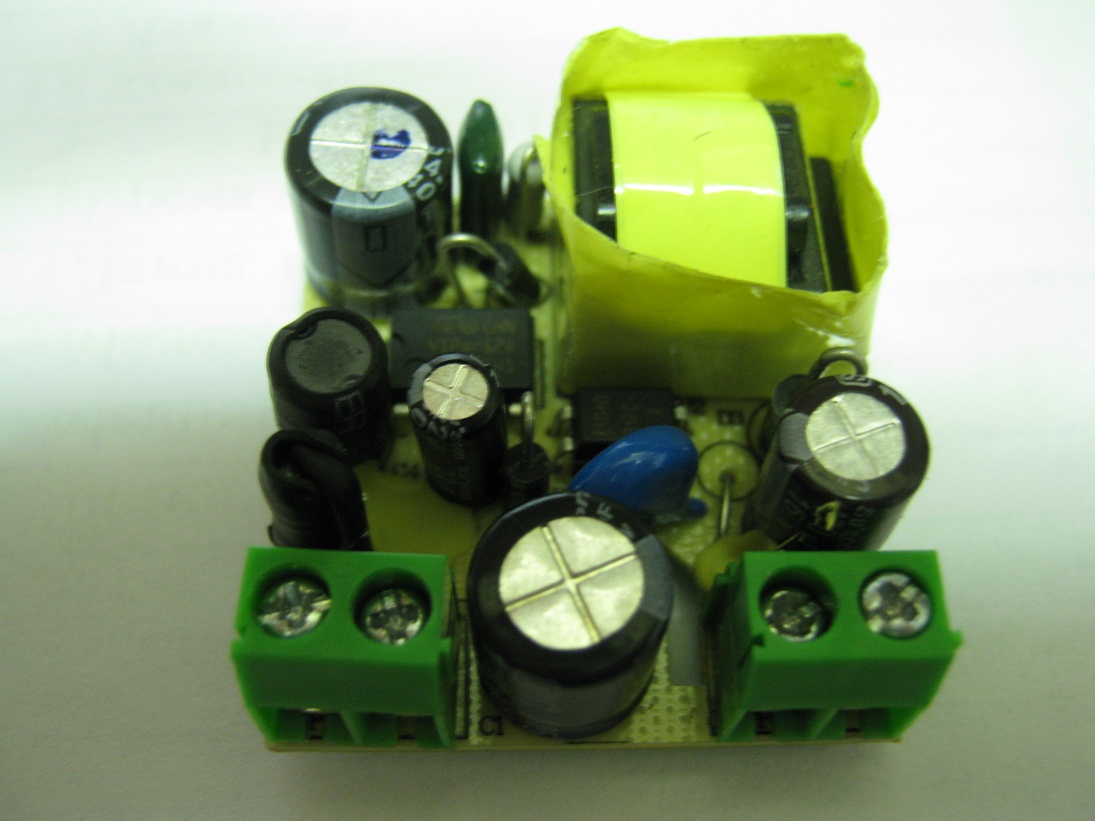
Photo of the entrails:
Link to the documentation for this power supply.
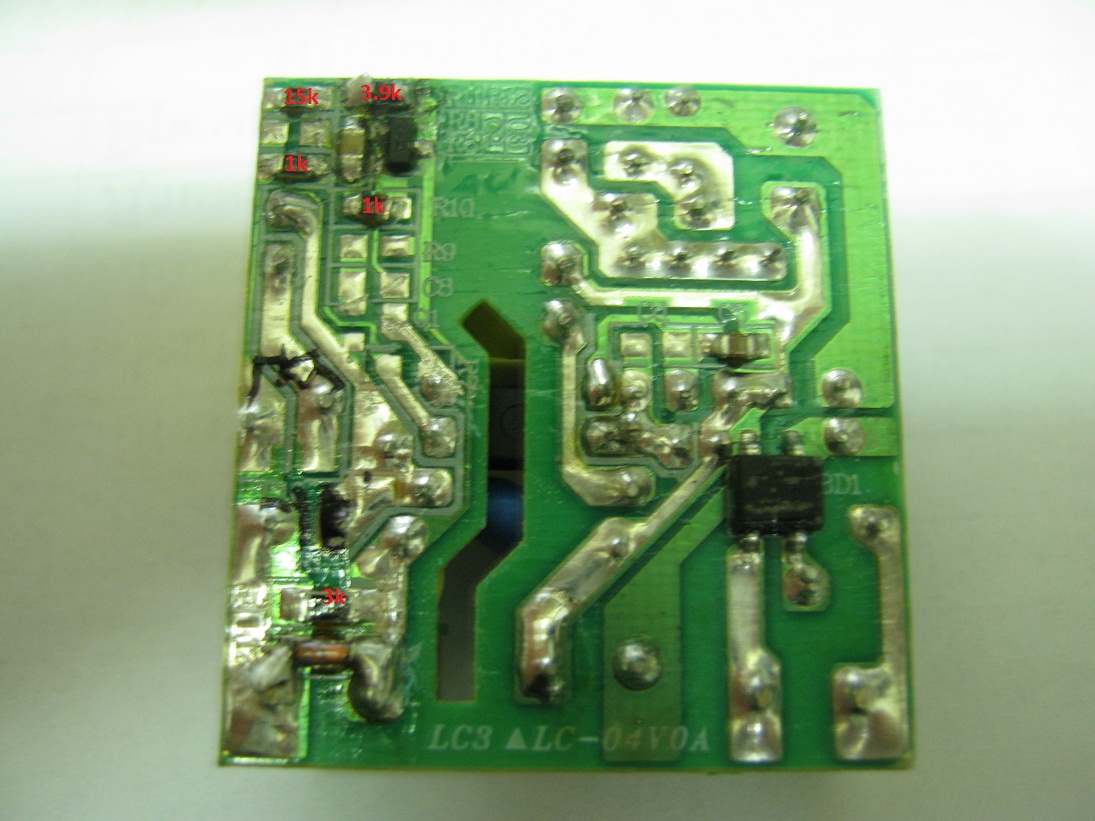
At first it was necessary to figure out what he was like, for this I had to draw a circuit diagram. The difficulty of dialing, and without it it is very difficult to track where the path goes, was that the board was coated with varnish, and I had to remove it with a scalpel. The result is an approximate picture: the

primary circuit in this case, IMHO, it makes no sense ...
So, the voltage on the secondary circuit directly depends on the feedback (OS) on the LED of the optocoupler, which is set by the divider based on the transistor.
To increase the voltage it is necessary:
1) Reduce the resistance of the lower resistor of the divider R12 (3.9 kOhm)
2) Keep in mind that the filter capacitor is designed for 16V, which means that with a voltage above 16V a suitable capacitor of the corresponding voltage
3) At the output of the circuit there is a zener diode of about 14.8V ( was empirically determined), then either vypayat (he protective, overvoltage) or replace large denomination
to reduce stress:
1) Increase of the lower resistance of the resistor divider R12 (3.9kOm)
2) Skipping
3) is also required to replace the stabilization ron or vypaevaem
It should be borne in mind that with increasing voltage, the output current decreases, in what relation I can’t say, you can start from P = UI, but I'm not sure that everything is so simple ... You can talk about increasing the output current with decreasing voltage, but again - all at your own peril and risk.
I needed an output voltage of 14.5V, for this I soldered a 15kΩ resistor in parallel with a 3.9kΩ resistor, as a result the resistance became ~ 2.7kOhm and an output voltage of 14.5V - profit!
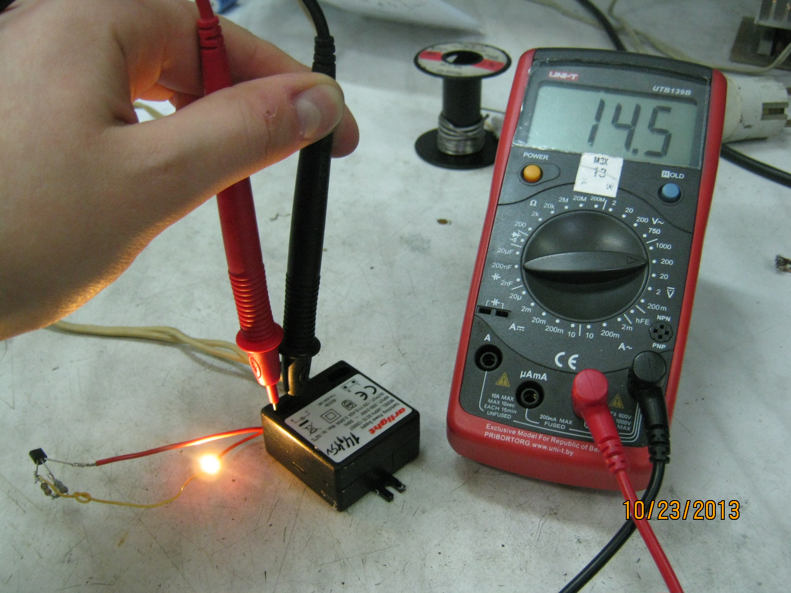
Photo of the entrails:
Link to the documentation for this power supply.
At first it was necessary to figure out what he was like, for this I had to draw a circuit diagram. The difficulty of dialing, and without it it is very difficult to track where the path goes, was that the board was coated with varnish, and I had to remove it with a scalpel. The result is an approximate picture: the
primary circuit in this case, IMHO, it makes no sense ...
So, the voltage on the secondary circuit directly depends on the feedback (OS) on the LED of the optocoupler, which is set by the divider based on the transistor.
To increase the voltage it is necessary:
1) Reduce the resistance of the lower resistor of the divider R12 (3.9 kOhm)
2) Keep in mind that the filter capacitor is designed for 16V, which means that with a voltage above 16V a suitable capacitor of the corresponding voltage
3) At the output of the circuit there is a zener diode of about 14.8V ( was empirically determined), then either vypayat (he protective, overvoltage) or replace large denomination
to reduce stress:
1) Increase of the lower resistance of the resistor divider R12 (3.9kOm)
2) Skipping
3) is also required to replace the stabilization ron or vypaevaem
It should be borne in mind that with increasing voltage, the output current decreases, in what relation I can’t say, you can start from P = UI, but I'm not sure that everything is so simple ... You can talk about increasing the output current with decreasing voltage, but again - all at your own peril and risk.
I needed an output voltage of 14.5V, for this I soldered a 15kΩ resistor in parallel with a 3.9kΩ resistor, as a result the resistance became ~ 2.7kOhm and an output voltage of 14.5V - profit!