Budget TimeLapse Slider do it yourself

Hello. I want to share my experience in manufacturing a simple and affordable TimeLapse slider 2 meters long for the camera (in my case, the phone acts as a camera).
The need for production arose in connection with the desire to take part in the festival of mobile cinema Velcom SmartFilm 2013, which takes place in Belarus.
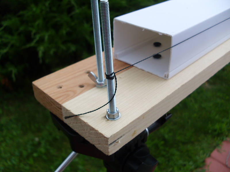
And so ... The slider consists of 2 main parts: mechanical (guides, moving carriage and movement mechanism) and electric (motor and control system). If everything was more or less clear with the last part of the slider, the LaunchPad MSP430 bundle + L298N driver + bipolar stepper motor from an old printer. That mechanics made pretty think, because everything should be "cheap and cheerful." Options with purchased guides disappeared immediately after examining their prices. And in the end, after a long search on the Internet, I settled on using a plastic box for laying cables 60 mm wide. It turned out to be quite durable and smooth for smooth movement of the carriage, but too flexible and therefore the snap-on lid of the box was screwed with screws to a glued board of suitable sizes (15 mm thick, 90mm wide and a little longer than the length of the box). Next, we snap the box onto the lid and get our guide. At the edges of the board, holes were made for attaching removable stands for tripods.
The carriage model was taken very widespread on the Internet. There is nothing complicated: an aluminum corner (you can buy it at the nearest hardware store, I just recommend the one that is thicker), 8 bearings (I found with an inner diameter of 8 mm) and a few nuts, bolts, washers and engravers. Cut, drill and assemble. The most important thing is to correctly mark the holes for mounting the bearings, otherwise the carriage will not touch the surface of the box with all the bearings and a slight play will appear.
Top view of the
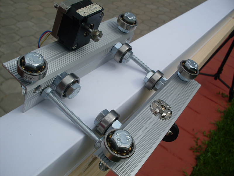
carriage
The movement mechanism was originally planned to use a 2 meter long hairpin and nut, but the stud sagged so much that even reducing the long slider to 1.4 meters did not allow it to be used. The only right and right decision was to use a timing belt, but it wasn’t at hand and ordering from China and waiting did not suit me (the festival was running out of time). Somehow, by chance, the idea came up of using a thread instead of a belt. The first tests exceeded all expectations - it worked and worked very well. It was done like this: on one side of the slider at the height of the shaft, fixed stepper motor. a nylon thread was tied, then one turn was made around the motor shaft and then the thread was pulled and tied on the other side of the slider.
We turn to the electrical part.
The control system can adjust the speed from 1 to 1024 engine steps per second and change the direction of movement. Modestly, but I do not need more.
The “brain” of the control system is LaunchPad MSP430 (msp430g2553). The code is very simple and written in Energia. The code is universal and can easily be redone for any Arduino board. Although 400 steps per revolution were written on a bipolar stepper motor, in practice it turned out only 200. To increase the smoothness of work at low speeds, I decided to use the motor control in half-step mode and we get our 400 steps / rev. back.

Program Code for MSP430
/* Программа управления слайдером для съемки Time Lapse */
 int m1=8;
 int m2=9;
 int m3=10;
 int m4=11;
 int key=5;
 int analog=A0;
 int time=0;
 int keyin=0;
void setup()
{
  pinMode(m1, OUTPUT);
  pinMode(m2, OUTPUT);
  pinMode(m3, OUTPUT);
  pinMode(m4, OUTPUT);
  pinMode(key, INPUT_PULLUP);
}
void loop()
{
  keyin=digitalRead(key);
 if (keyin==HIGH)
  {
  time = analogRead(analog); // step 1
  digitalWrite(m1,HIGH);
  digitalWrite(m2,LOW);
  digitalWrite(m3,LOW);
  digitalWrite(m4,LOW);
  delay (time+1);
  time = analogRead(analog); // step 2
  digitalWrite(m1,HIGH);
  digitalWrite(m2,LOW);
  digitalWrite(m3,HIGH);
  digitalWrite(m4,LOW);
  delay (time+1);
  time = analogRead(analog); // step 3
  digitalWrite(m1,LOW);
  digitalWrite(m2,LOW);
  digitalWrite(m3,HIGH);
  digitalWrite(m4,LOW);
  delay (time+1);
  time = analogRead(analog); // step 4
  digitalWrite(m1,LOW);
  digitalWrite(m2,HIGH);
  digitalWrite(m3,HIGH);
  digitalWrite(m4,LOW);
  delay (time+1);
  time = analogRead(analog); // step 5
  digitalWrite(m1,LOW);
  digitalWrite(m2,HIGH);
  digitalWrite(m3,LOW);
  digitalWrite(m4,LOW);
  delay (time+1);
  time = analogRead(analog); // step 6
  digitalWrite(m1,LOW);
  digitalWrite(m2,HIGH);
  digitalWrite(m3,LOW);
  digitalWrite(m4,HIGH);
  delay (time+1);
  time = analogRead(analog); // step 7
  digitalWrite(m1,LOW);
  digitalWrite(m2,LOW);
  digitalWrite(m3,LOW);
  digitalWrite(m4,HIGH);
  delay (time+1);
  time = analogRead(analog); // step 8
  digitalWrite(m1,HIGH);
  digitalWrite(m2,LOW);
  digitalWrite(m3,LOW);
  digitalWrite(m4,HIGH);
  delay (time+1);
 }
  else
  {
  time = analogRead(analog); // step 8
  digitalWrite(m1,HIGH);
  digitalWrite(m2,LOW);
  digitalWrite(m3,LOW);
  digitalWrite(m4,HIGH);
  delay (time+1);
  time = analogRead(analog); // step 7
  digitalWrite(m1,LOW);
  digitalWrite(m2,LOW);
  digitalWrite(m3,LOW);
  digitalWrite(m4,HIGH);
  delay (time+1);
  time = analogRead(analog); // step 6
  digitalWrite(m1,LOW);
  digitalWrite(m2,HIGH);
  digitalWrite(m3,LOW);
  digitalWrite(m4,HIGH);
  delay (time+1);
  time = analogRead(analog); // step 5
  digitalWrite(m1,LOW);
  digitalWrite(m2,HIGH);
  digitalWrite(m3,LOW);
  digitalWrite(m4,LOW);
  delay (time+1);
  time = analogRead(analog); // step 4
  digitalWrite(m1,LOW);
  digitalWrite(m2,HIGH);
  digitalWrite(m3,HIGH);
  digitalWrite(m4,LOW);
  delay (time+1);
  time = analogRead(analog); // step 3
  digitalWrite(m1,LOW);
  digitalWrite(m2,LOW);
  digitalWrite(m3,HIGH);
  digitalWrite(m4,LOW);
  delay (time+1);
  time = analogRead(analog); // step 2
  digitalWrite(m1,HIGH);
  digitalWrite(m2,LOW);
  digitalWrite(m3,HIGH);
  digitalWrite(m4,LOW);
  delay (time+1);
  time = analogRead(analog); // step 1
  digitalWrite(m1,HIGH);
  digitalWrite(m2,LOW);
  digitalWrite(m3,LOW);
  digitalWrite(m4,LOW);
  delay (time+1);
}
}
We connect the engine to the controller through the L298N driver, a direction selector switch, a variable resistor (speed controller), and an LED, which will be an indicator of the inclusion of our system.
A small plastic breakfast container was ideally suited for the role of a remote control case.
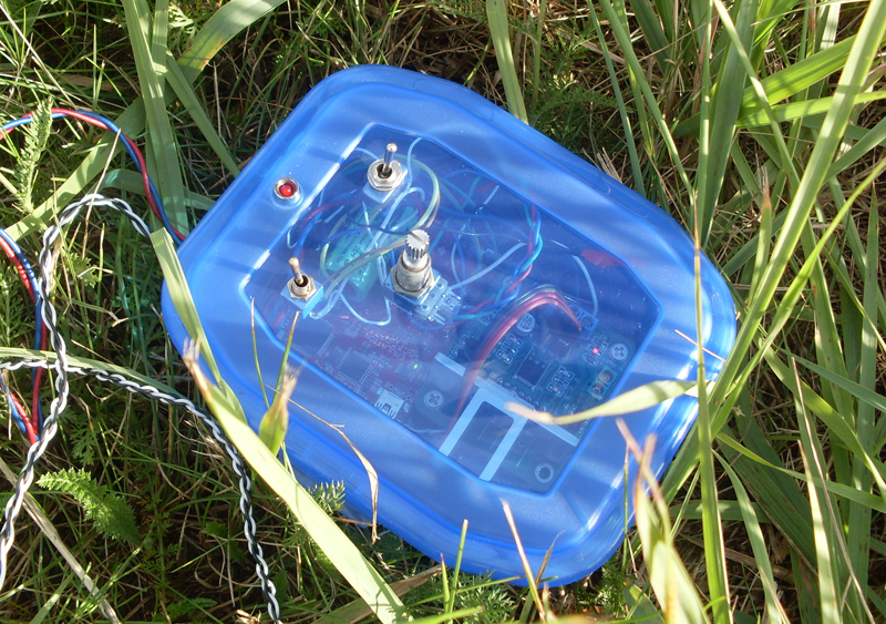
A small-sized 3V battery was chosen as the power source for the controller, and a standard 6V 4.5Ah battery was used to power the engine. To supply power, a toggle switch with a pair of contacts is provided, which connects both the battery and the battery to the driver and controller, respectively. Measurements showed that in 4 out of 8 steps the engine consumes 0.45 A, and in the remaining 4 steps out of 8 - 0.9 A. It turns out that something is about 0.7 A - this is a roughly average consumption of the engine, which gives we need about 5-6 hours of work from a fully charged battery (in reality, it is).
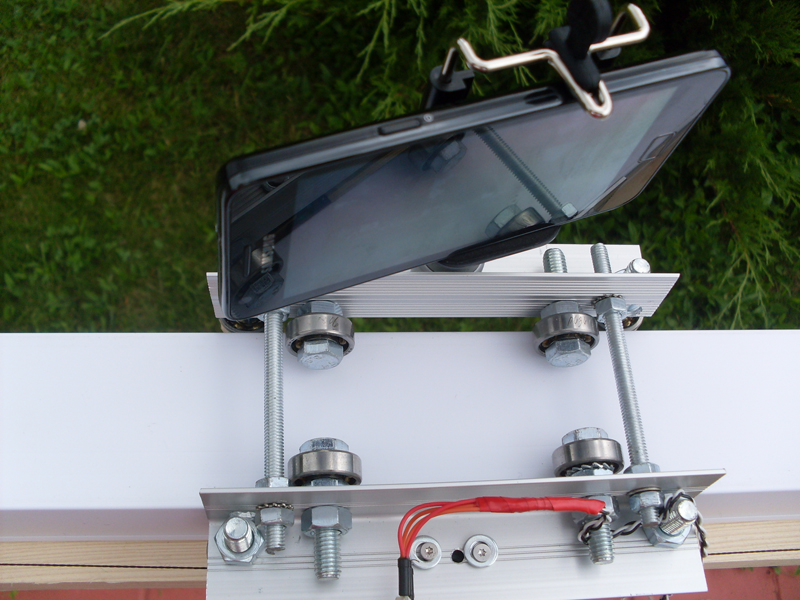
View of the slider itself.

Video Slider at work.
For greater clarity. Watch the video of the first test. The black thing on the laptop is the Battery GP1245 (12V 4.5 Ah) weighing about 2 kg. The laptop itself weighs about 2.5 kg. In total, a load of 4.5 kilograms travels without any problems.
During operation, the following disadvantages were noticed:
1. The thread stretches over time (but this has almost no effect on the work)
2. Sometimes the input and output of the thread in the loop around the shaft are crossed and this causes a slight twitching of the carriage.
3. The glued board slightly bent over time (not critical for me)
This is the first article, so do not judge much.
Oh yes ...
Here is the video for the festival, where you can see what I filmed using this slider.
Thank you all for your attention.