DIY Dimmer For Those Who Want Itself

In the process of developing any project, many control points can change. Sometimes very dramatically. Today we decided to try to change one of these points of our project and publish the circuit and design of the printed circuit board of the last, grocery, revision of our DIY dimmer. So that everyone can assemble our scheme and play with it right now, without waiting for the ready-made beautiful boxes “for everyone” to appear on the shelves.
For newcomers, the previous series of our "series": the first , second and third . This is the fourth.
Changelog
The second revision of the board could become smaller both horizontally - 40x45mm and vertically - the estimated height is about 16mm without a case, with a case it will be about 18mm. Such dimensions will allow our modules to fall into most of the wall boxes in this country.
Habrahabr spotted a startup in us and gave us his special corporate account . Who wants to follow the events around the project - subscribe to it, not all of our events will shine anywhere except for your corporate blog.
Our developer of the power unit has finally received the hubfl account alexfl and has already begun to respond to the dangling comment threads about the details of the iron power unit. So now you can forget about deaf telephones when I had to broadcast his answers to the hub.
In the process of minimizing the board, we had to switch to another, smaller type of NRF24LE1 modules with a lead spacing of 1.27 mm. With them there are minor difficulties when buying. Gentlemen, the Chinese make such modules of different sizes with different distances between the output tracks. Later, a buying guide will be published so that no one makes a mistake. And for those who still make a mistake, the power board is divorced in a cunning way, so that you can put a wide module too.
Also, in the minimization process, I had to reduce the number of GPIOs brought out. Now we do not display all, but only one side of the module. Which in any case should be enough for most applications. The findings themselves became the same in increments of 1.27 instead of the former 2.54 mm.
Thanks to so unexpected cooperation with MakeItLabour project should accelerate significantly. We got several types of 3D printers, CNC machines, many other interesting equipment at our disposal, and most importantly, people who have the time and desire to help, who are interested in the development of the project. I will compose separate posts on the results of this cooperation.
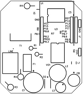
Circuit diagram

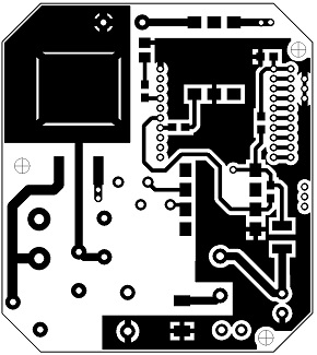
PCB design
Top side:

Bottom side:

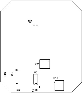
Arrangement of elements
Top side:

Bottom side:

And at the end of the post
When submitting an application for registering a corporate account, we had to reveal all the cards - and the name of the project that had been invented a long time ago and a link to a site that was not yet filled. Therefore, we ask you to love and favor our name - CoolRF. It’s not worth looking at the site yet, nothing worthwhile has been posted there yet (a link to the project’s site was a mandatory requirement of the questionnaire).
And this is what the brand name of the module will look like, which we will use in the future:

