DIY lid for the bin
In the article I’ll tell you how to turn an ordinary bucket with a lid into an automatic one.
He went to the bucket - the lid opened, put what was needed in it, went away - the lid closed.
The bucket was used shiny metal, the lid opens with a pedal, such buckets can be found in many stores.
To finalize the bucket, an IR LED, an IR receiver, a servo drive, and a microcontroller were used.
Management and control of the servo overload is carried out using the Atmel microcontroller ATtiny44A.
The management program is written in C at Atmel Studio 6.1.
Electronic filling
Work algorithm
- The IR LED constantly sends a certain binary code, the IR receiver reads it and if a coincidence occurs, a command to open the lid is issued.
- After opening the lid, wait 7 seconds and close the lid if the sensor is not active.
- If during opening the lid rested against an obstacle, then we squeak, wait for some time (3 sec) and try again. In case of repeated failure, we “fall asleep” for a longer time (60 sec).
IR Sensor
The principle of operation is based on the property of reflection of infrared rays from an obstacle.
The IR diode sends a modulated code message into space, and the IR receiver receives it.
To regulate the transmission power, a trimming resistor RV1 is used.
The carrier frequency of the signal is 38 kHz.
Biphasic (Manchester) coding is used. It does not require quartz frequency stabilization.
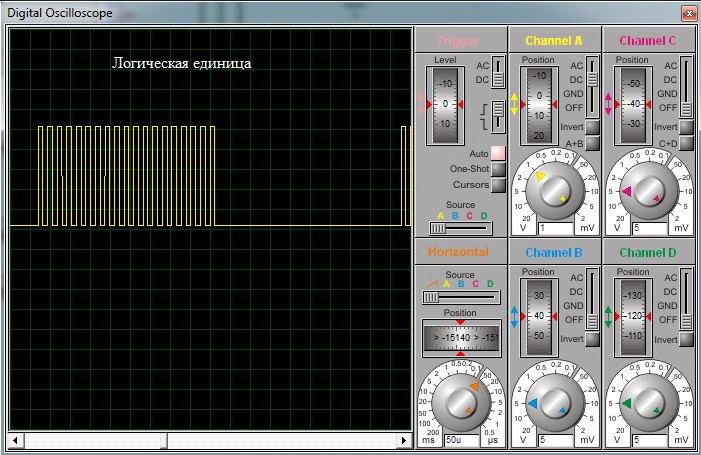
Here are the bit coding waveforms:

Here is the packet waveform: The
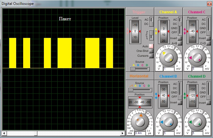
IR receiver (I used Vishay TSOP4838) receives the signal, decodes and outputs the packet in inverted form.
The packet is repeated after a certain time:
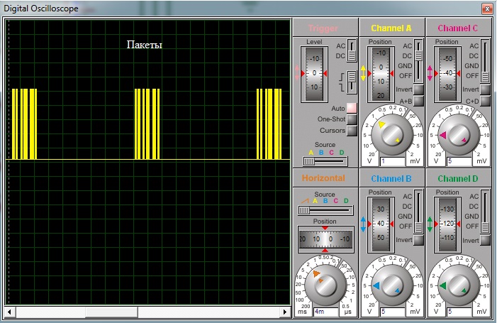
The IR receiver is a smart device and tries to filter out the signal, suppressing interference, various pulses that do not fit his understanding of a suitable packet format.
Therefore, between packets there must be a pause not less than the minimum.
For example, when using TSOP4838, if you pause 15 bits with a packet length of 8 bits, the receiver will often skip packets.
With a pause of 30 bits - packets are not passed.
Servo
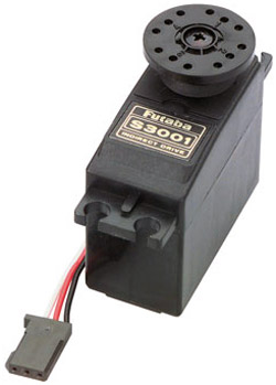
To open the lid, a standard Futaba S3001 service is used.
She has an output force of 4.8 kg-cm at 4.8 V, and 3 kg-cm at 6 V.
The cover is metal and relatively heavy, but this servo is enough for it.
Power is supplied to the servo only for the duration of its positioning. For this, a Logic level MOSFET transistor is used.
A 0.5 ohm resistor is used to control the current consumed by the servo drive.
The microcontroller measures the voltage drop across it and, if exceeded, turns off the power to the servo.
The peak value of the consumed current during the opening of the lid is 500 mA, during closing - 150 mA, with "jamming" - 550 mA.
The servo drive is controlled by pulses with a duration of 1.1 to 1.8 ms, which follow every 0.02 seconds.
After the end of the control pulse, the servo drive, if necessary, begins to be positioned.
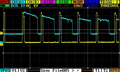
Oscillograms:
Yellow - control pulses, blue - servo consumption (voltage drop on the shunt).
Here is the waveform of the start of the normal positioning of the servo:
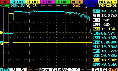
Normal positioning, somewhere in the middle of the movement:

Here are the waveforms of the servo jamming:
At the start, hold with your hands:
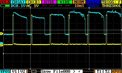
As you can see, at the very beginning there is a fairly large consumption practically regardless of whether the servo can move or not.
It is also seen that the instantaneous consumption of the servo drive cannot be greater than a certain value, and to control the impossibility of moving the drive, it is necessary, in the ideal case, to calculate the area under the blue graph.
In the program, the voltage drop across the shunt is read using the ADC and a simple method of summing the instantaneous values during the period is used. If the amount exceeds a certain threshold, the servo stops.
The threshold is selected experimentally.
The value at which the protection triggered is stored in the EEPROM.
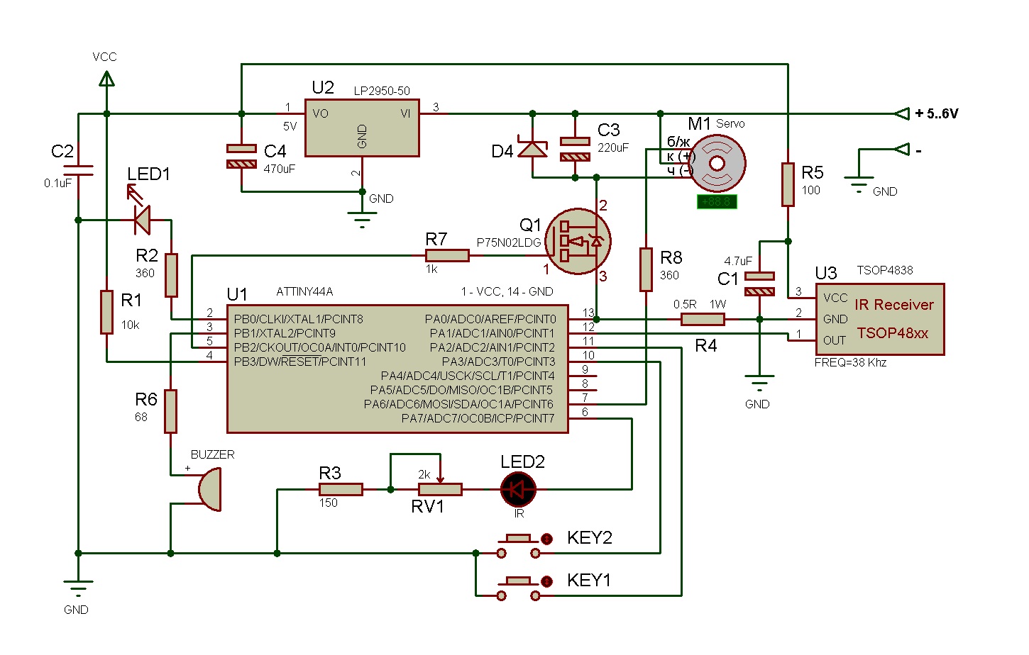
Scheme:
Program
The program is written in C in Atmel Studio 6.1.
Used AVR ATtiny44A microcontroller with 14 pins in a DIP package.
It operates at a frequency of approximately 7904000 Hz in order to easily obtain 38000 Hz for the IR LED.
The default frequency is 8 MHz, and the frequency 7.9 MHz is obtained by changing the OSCCAL register.
I got the value 0xA7 at a voltage of 5 V.
When the supply voltage or temperature changes, the frequency will go a little, but this does not affect the performance of the IR sensor.
For transmission - reception of the IR signal, servo control, timing, a single 8-bit timer is used, operating at a frequency of 988 kHz and configured for Fast PWM mode.
The signal frequency is set by the OCR0A register. It contains the value at which the timer counter (TCNT0) will be reset.
The value defining the duty cycle of the pulses is entered in OCR0B. In our case, 50%.
The timer is configured so that the change of value at the output of the controller to which the IR diode is connected occurs 2 times per period (set by OCR0A) - at zero TCNT0 and when TCNT0 is OCR0B.
In the interrupt on equality TCNT0 and OCR0B, all the work of receiving and transmitting an IR signal is performed.
ISR(TIM0_COMPB_vect)
{
 	staticuint8_t IR_error = 0;
	if(++IR_pulsecnt == IR_BIT_LENGTH/2)
	{
		if(IR_pausecnt == 0)
		{
			if(((IRSENS_IN & IRSENS) == 0) != ((TCCR0A & (1<<COM0B1)) != 0)) IR_error = 1;
			TCCR0A ^= (1<<COM0B1);
		}
	} elseif(IR_pulsecnt == IR_BIT_LENGTH)
	{
		IR_pulsecnt = 0;
		if(IR_pausecnt)
		{
			if(--IR_pausecnt == 0)
			{  // after pause send again
				IR_send = IR_SENDDATA;
				goto IRStartSending;
			}
		} else {
			if(IR_send == 0)  // Packet was sent
			{
				if(IR_error == 0) IRDetected = 1; else IR_error = 0;
				IR_pausecnt = IR_PAUSEBITS;
				TCCR0A &= ~(1<<COM0B1); // assumes that COM0B0 = 0
			} else
			{
IRStartSending:
				TCCR0A = (TCCR0A & ~((1<<COM0B1))) | ((1<<COM0B1) * (IR_send & 1));
				// assumes that COM0B0 = 0, if 1 - generate (Clear OC0B on Compare Match, set OC0B at BOTTOM)
				IR_send>>=1;
			}
		}
	}
}
The peculiarity of the send function is that a packet is considered to be sent when the bit buffer is 0. This means that in the high order bit of the packet there must always be one.
IR signal generation starts when the COM0B1 bit is set in the TCCR0A register. It is understood that the COM0B0 bit is 0 and has not been set anywhere before.
Servo control, time countdown, button chatter suppression are performed in the interrupt for overflow of the same timer.
In standard mode, opening the lid is performed in two stages - first several cycles slowly, then quickly until it is completely opened. Made to reduce the load on the servo drive and traction.
The first button is used to manually open or close the lid.
The second button to stop the opening and to enable / disable the quick opening mode.
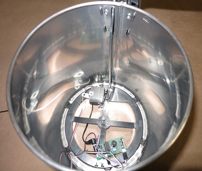
Assembly
The servo is connected to the vertical link, the horizontal link and pedal are thrown out.
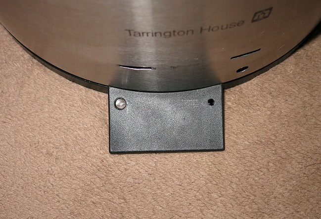
The IR diode and receiver are mounted in a protruding plastic leg. There is just enough space for them.
Video:
Source:
yadi.sk/d/OGTOvX73Agk8h