Overview of the new TI Launchpad (MSP-EXP430F5529LP or MSP430F5529 USB LaunchPad)
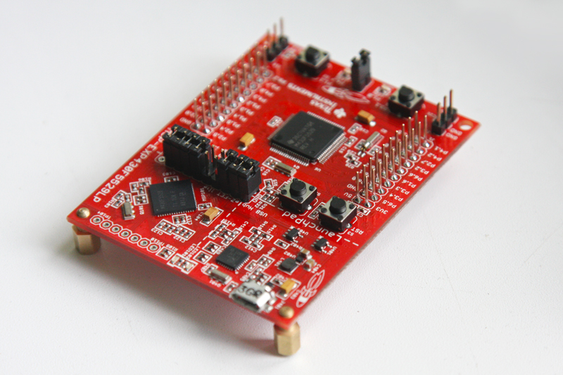
Not so long ago, TI posted a new debugging board from the Launchpad series in public (judging by http://www.ti.com/ww/en/launchpad/overview_head.html this board is used as a replacement for the first launchpad).
Literally today, this device fell into my hands; accordingly, a further illustrated review was written in honor of this event.
Specifications:
- Core Frequency 25MHz
- Memory: 128KB flash, 8kB RAM
- 16-channel 12-bit ADC
- comparator
- four 16 bit timers
- 2 I2C, 4 SPI, 2 UART, USB (connected via USB hub)
- 40 pin connector for BoosterPacks (as on TivaC / Stellaris launchpad)
- MSP430-F5529 - one of the senior microcontrollers in the 5x series
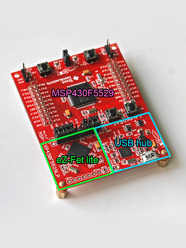
What sets this board apart from others? Mostly the presence of a built-in USB controller, which allows you to use it as a basis for a variety of USB peripherals for PC / Mac. In msp430f5529, a demo with the implementation of the HID keyboard and Mass Strorage drive is already wired. Of course, it is also very good that it has a microcontroller from the relatively new 5x series, in which, unlike the 2x series, there are many interesting peripherals, for example, DMA, Port Mapping Controller.
Options (unlike the “first” Launchpad, this board comes fully assembled, that is, there is no need to solder a rather small crystal and connectors):
- pay
- micro usb cord
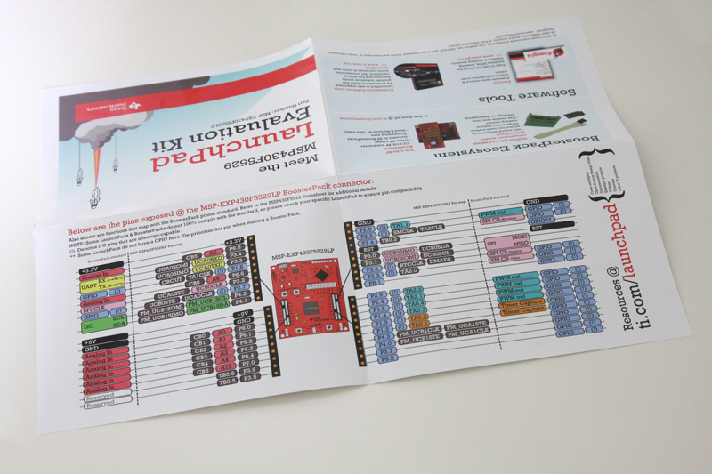
- Beautiful brochure with illustration of pinout board and tool guides documentation.
Also a very interesting point in this board is the presence of a new programmer / emulator / debugger eZ-FET lite , which is positioned as an open source.
EZ-Fet lite has its own page on the TI website
http://software-dl.ti.com/msp430/msp430_public_sw/mcu/msp430/MSP430_ezFETLite/latest/
where you can get firmware, circuits, source codes and a manual.
(most likely it is not a true open source because it requires the closed MSP430.DLL to work)
Characteristics of eZ-Fet lite 1.10:
- USB debugging, firmware
- UART communication at speeds up to 1MBaud
- ability to update firmware
- support for all microcontrollers architecture MSP430
- software - MSP430.DLL version 3.3.0.6 or later, Code Composer Studio version 5.4 or later, IAR Embedded Workbench version 5.50 or later
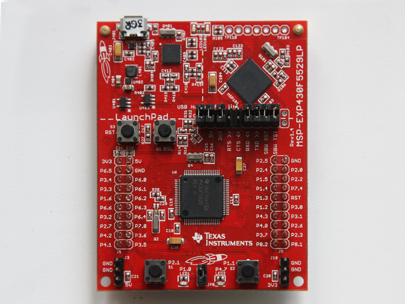
One more photo:

Fast start:
Recently, TI has begun to design a “Project 0” for each of its boards, which should allow them to quickly plunge into development, this board also has such a project. The start page of the "Zero" project http://processors.wiki.ti.com/index.php/MSP430F5529_LaunchPad - on this page all the links necessary to start are collected.
Briefly retell Project 0, here's what you need to do:
- download Code Composer Studio
(CCS) from the TI website (this is probably the most difficult) - to do this, go to http://processors.wiki.ti.com/index.php/Download_CCS
and click on the button under "Download the latest CCS" , further it is required to fill out a questionnaire stating that we do not plan to use this software for military purposes and only after that we will be allowed to get a free version of CSS limited to 16kB code. - After we got CCS, you should install it with the usual installer
- Next, you need to start it and create a project File> New> CCS Project, in the wizard select as device MSP430F5529, select Empty Project (with main.c).
- After creating the project, you can insert the code into it:
#includeunsigned int i = 0; // Initialize variables. This will keep count of how many cycles between LED toggles void main (void) { WDTCTL = WDTPW + WDTHOLD; // Stop watchdog timer. This line of code is needed at the beginning of most MSP430 projects. // This line of code turns off the watchdog timer, which can reset the device after a certain period of time. P1DIR | = 0x01; // P1DIR is a register that configures the direction (DIR) of a port pin as an output or an input. // To set a specific pin as output or input, we write a '1' or '0' on the appropriate bit of the register. // P1DIR = // Since we want to blink the on-board red LED, we want to set the direction of Port 1, Pin 0 (P1.0) as an output // We do that by writing a 1 on the PIN0 bit of the P1DIR register // P1DIR = // P1DIR = 0000 0001 // P1DIR = 0x01 <- this is the hexadecimal conversion of 0000 0001 for (;;) // This empty for-loop will cause the lines of code within to loop infinitely { P1OUT ^ = 0x01; // Toggle P1.0 using exclusive-OR operation (^ =) // P1OUT is another register which holds the status of the LED. // '1' specifies that it's ON or HIGH, while '0' specifies that it's OFF or LOW // Since our LED is tied to P1.0, we will toggle the 0 bit of the P1OUT register for (i = 0; i <20000; i ++); // Delay between LED toggles. This for-loop will run until the condition is met. // In this case, it will loop until the variable i increments to 20000. } }
and press the Debug button (F11), after which, if everything is connected and configured correctly, we will go to the debugger (where we can go through the code and look at the registers) in which we just press Resume (F8) and enjoy the LED blinking (CCS can also suggest update eZ-fet lite firmware).
Also, as an option, it is supposed to be able to use Energia to use this board by analogy with arduino.
In my opinion, the board turned out to be very successful and without strong difficulties allows us to assemble some usb device.
(For those who are faced with such boards for the first time, I want to note that it, like other launchpads, is in fact a cheap Spy-by-Wire programmer / debugger for almost any MSP430 controllers, i.e. it can be connected using a pair of wires to an external device and flashing / debugging it from CCS and other IDEs (and unlike the expensive JTAG MSP430-FET UIF, you can connect directly to the controllers legs)).
PS. The fee costs $ 12.99 you can order as in the office. TI store and various distributors, but it will be more expensive (for example here ), I think soon it will be possible to buy in our retail.