On the issue of pulsations, interesting people and inductances
Law 14 (Edison's Law) 'Better' is the enemy of 'good'
Recently, my colleague, whom I repeatedly mention in my posts (as a rule, in the role of Dr. Watson’s reincarnation, the main purpose of which is to give a shine to the main character of the presentation, I have such evil jokes, Danil), decided to master the design of power sources (for low-power start, but we'll see). Since it happens in the 201s, transistors are cheap and small (even with drivers), and inductances are large and expensive (well, not as big as they used to be, but still not small), a down-boosting non-inverting (bridge) circuit with a microcontroller is selected role of the control element. A number of interesting questions are connected with this scheme, some of which are answered in Ann448 from ST (not all of them are not complete, perhaps I will write more about this), but this is now a little about something else.
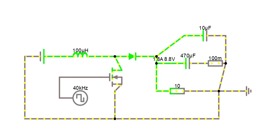
After assembling the scheme, a colleague wrote a series of tests that allowed to check the correctness of the scheme (and errors were found and corrected) and the functioning of individual elements (the error was also found and fixed). (I don’t understand, Danil, why don’t you write about it yourself, especially about the output key booster - very instructive). One of the tests was the operation of the device as a step-up power source with a fixed fill factor, which in general was confirmed, the output voltage varied in accordance with the design model. Well, in the end we decided to look at the voltage ripple at the source output. The equivalent scheme for the mode under study is presented on the KDPV.
And here a slightly incomprehensible phenomenon was waiting for us - the output oscillogram was quite different from that calculated both in the amplitude of the pulsations (well, this is generally expected, since the parameters of real components will always differ from those indicated in the specification, but not in the same). waveform (and this is completely incomprehensible). The specific waveform is shown in Figure 1 (in green), it also has the expected shape of the pulsations (in red), it seems to me that the difference is obvious. It is most surprising that the capacitor is constantly discharged (except for the abrupt transition sections), which is in stark contradiction with the theoretically predicted equality to zero of the average current through the capacitor over a period in a steady state on which the whole method of calculating the converter is based.
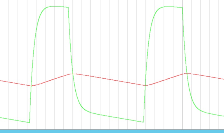
We begin to argue. Abrupt voltage spikes are perfectly explained by the presence of a significant ESR capacitor, and we can even estimate its value = dU / I / 2, which gives us 100 mΩ - a lot, of course, but quite possible. But why we do not see a characteristic increase in the voltage on the capacitor in the cycle of power transmission from inductance? More research is needed, and for this you need to play the defect on another device. Since there is no possibility to collect a second fee (more precisely, there is no desire, this is the determining factor), we need a virtual circuit and the google “simulator of electronic circuits online” leads to the absolutely charming site falstad.com. (Necessary note - the author knows about the existence of many other simulators, and he used them repeatedly,
I find a simulation program, read the history of its creation, and I understand that this is an indie project, that is, a person (in his spare time) writes a simulator (in Java), supplies it with a set of models and supports the site with this application - just to go nuts. I understand the basic principles of simulating electronic circuits, I can assume that a number of models lie in an accessible form on the web, but, nevertheless, I did not write such a simulator (and the vast majority of habravchan too). But suppress the feeling of light envy and proceed to the study of the problem scheme.
I make up the model of the scheme, not immediately, but (with the help of video lessons) I master the visualization of the results in the form of oscillograms (this program allows us to monitor the movement of current in the circuit under study in the form of miniature circles, which is fun and informative, but not very informative, although show and the movement of electrons, then the circles will run in the opposite direction, which is even more funny, although not more informative) and observe the results. The reception of the result fully coincides with the theoretically predicted, which is not surprising - we have all the elements perfect, as in the calculation.
I could not insert the link, here is its text
www.falstad.com/circuit/circuitjs.html?cct=$+1+1e-9+19.867427341514983+44+5+50%0Al+368+240+464+240+0+0.00009999999999999999+2.6008195407028163%0Ac+624+256+704+256+0+0.00047+8.587226788166596%0Ar+592+320+688+320+0+10%0Ad+496+240+576+240+1+0.805904783%0Ag+768+320+800+320+0%0Av+288+240+368+240+0+0+40+5+0+0+0.5%0AR+368+336+416+336+0+2+40000+25+25+0+0.66%0Aw+592+320+592+256+0%0Aw+592+256+624+256+3%0Aw+688+320+736+320+0%0Aw+752+256+736+320+0%0Aw+736+320+768+320+0%0Aw+288+240+288+320+0%0Aw+464+240+496+240+0%0Aw+576+240+592+240+0%0Aw+592+240+592+256+0%0Aw+496+240+512+272+0%0Aw+512+304+496+320+0%0Aw+368+288+464+288+0%0Aw+736+320+736+384+0%0Aw+736+384+496+384+0%0Aw+496+384+288+384+0%0Aw+288+384+288+320+0%0Aw+496+320+496+384+0%0Aw+368+288+368+336+0%0Af+464+288+512+288+0+1.5+0.02%0Ar+704+256+752+256+0+0.1%0Ac+656+192+752+192+0+0.000009999999999999999+8.50394262258968%0Aw+752+192+752+256+0%0Aw+656+192+592+240+0%0Ao+18+64+0+4099+80+0.00009765625+0+2+18+3%0Ao+0+64+0+4099+40+6.4+1+2+0+3%0Ao+8+64+0+12290+8.751594683701885+0.0001+2+2+8+3%0A
I add the expected value of resistance and I am surprised to see that the shape of the pulsations changed dramatically and completely coincided with what was observed in the experiment, which is good news, which means that we can continue to study the model. First of all, I measure the voltage on the capacitor and I am happy to see that the voltage-second balance is not disturbed and the capacitor, as it should, is charged and discharged during the operating cycle. Then it becomes clear the behavior of the voltage across the load is the sum of the voltage across the capacitor and the voltage drop across the resistance, which is proportional to the current flowing. Since the current through the inductance changes (decreases) during the transfer of energy from the inductance to the capacitance, this leads to a decrease in the drop on the resistance and, starting with a certain value of the latter,
To test our hypothesis, let's play with the parameters of the scheme (I strongly recommend doing it yourself on the following page), first turn off the ceramic capacitor, this will remove the smoothing of the fronts with a time constant of 1 ms and allow you to observe the effects in their pure form. We begin to increase the resistance and see the appearance of a characteristic step, which begins to increase in size. From some point you can see that the angle of inclination of the direct voltage on the load on the charge section begins to decrease until the segment becomes horizontal, and then turns into a falling one.
We are conducting the last experiment, which will show that besides the current drop on the inductance, there are no other reasons for the voltage drop (we don’t see them, but it’s not enough ...) - it is necessary to reduce the current ripple in the inductance and the easiest way to achieve this is by increasing the inductance. In real life, the task of getting a 1 mf coil to 4A current would be difficult, but there is nothing simpler in the simulator - and for sure, the current ripple drops sharply and the output voltage again has a linearly increasing portion. As always, nothing miraculous happens and all processes in the scheme have a natural scientific explanation, CTD.
We return to the original living scheme, look at the parameters of the tank on the date, see the expected 100m ohms of resistance, ask the puzzled question “and why is it there,” we get the answer “200mcf was required by the calculations, I decided to put more” (“what Victor Stepanovich allows to recall the seer of the Vanga level ”- pity, not my phrase), we put two 100 µF ceramics lying on the table (100 microfarads of ceramics in millimeter dimensions, Karl - if I had been told this 20 years ago, I would simply have twisted my finger at my temple, and now they lying around ... component b because they made a huge leap over the years, although a circuit design can not be said, everything is thought out to us) and everything is just fine. What makes us remember another no less remarkable phrase "Do not, as it is better, it is necessary, as it should be."
In conclusion, I would like to thank Mr. Falstad for the pleasure of using his wonderful program and rejoice that such people are still being made, otherwise I became bored after Robert Pease left, and suddenly such a gift. Although not quite bored - 3 years ago I discovered for myself an amazing program and also a simulator - VMLab, and also in the status of free software - probably, in this concept, that is, since such wonderful people promote it. You can also remember the godbolt - also very well, probably, all the same, all is not lost and the phrase “such people no longer do” is not true, they do, they just do a little other things.
Ps. If we are talking about inductances (yes, we talked about them, though not for long), I would like to touch on the peculiarity (I would put it more strictly, but “toxic behavior” is not welcome in Habré) associated with the choice of inductance from standard products. The main parameter, along with the inductance itself, is the permissible current through the coil, and here there is an unpleasant nuance, which we will consider.
To begin with, let us define the danger of exceeding the maximum current (saturation current) - by the fact that, as it is not difficult to guess, the inductance enters the saturation mode, where there is no linear connection between the flowing current and the magnetization of the core, which leads to energy losses on the magnetization reversal. This parameter has 2 features that should be considered:
1. In fact, for each real inductance, this parameter is zero, since for any flowing current nonlinearity will occur and the only question is the degree of nonlinearity at a particular point. In my youth, it was customary to give a current value at which the loss is 5% (and this is the right approach), so you could be confident in the inductance at lower currents. Unfortunately, now some manufacturers indicate current at 20% of losses, others - at 30%, therefore, at currents close to the indicated ones, you will be very puzzled by the results obtained in terms of efficiency. Of course, the date honestly indicates the level of losses at the boundary current and you can always answer RTFM (F), but somehow it is not fair with respect to the expectations of the developers. I understand,
2. It is not the average current that is meant, namely the maximum current, and if you have short-term exceedances (and this is typical for switching power supplies) of the saturation current, then losses are inevitable, even if the average current is much less. This feature should just be clear and the manufacturers are honest here - you have to take this on your own. Hence the need to remain within the framework of the continuous mode, since it is in this mode that the ratio of maximum current to average is the smallest and lies from one to two.
But there is another parameter, which simply did not exist before. The fact is that in the last 10+ years a lot of excellent materials have appeared that have simply amazing parameters from the point of view of cores, first of all, magnetic permeability and frequency properties. All this allowed an order of magnitude (or even not one) to reduce the geometric dimensions of the winding elements, along with an increase in operating frequencies. But you have to pay for everything in this world - and if you could heat a transformer with a core of laminated iron to the melting point of copper wire (with a short circuit, it was not difficult) and it did not lose in efficiency at all (perhaps it did, but it was little noticeable) ,
So, the second parameter is the maximum allowable average current through the winding, due to the above reasons. As a rule, it is 2 times less than the saturation current (although this is not necessary), therefore, if you are on the border of the continuity mode, then everything is wonderful and all conditions are met (let's not forget about 20-30% loss), but if you are deep inside zone of continuity and maximum current = 120% of the average and does not well exceed the saturation current, then you still need to check the average current for admissibility. Hence the rule of thumb is to divide the saturation current of modern coils by about 1.5 (more is already overkill) and choose according to this criterion and you will be happy and highly efficient with the circuit developed by you.
By the way, good Chinese do just that - an inductance with a saturation current of 12A is put into the source for a current of 8A and everything works fine in efficiency for 90%.