Amateur Racing Timing, Flexible and Wireless
Hello.
For some time I became interested in amateur motorsport - no, not night street racing, but quite legal competitions held in the daytime and agreed with the relevant structures. As many people suspect, the purpose of such competitions is to drive the distance faster than the opponent. Why measure the distance.
The easiest way is to give the judges a stopwatch and teach them to press the Start / Stop button in time. The disadvantages of this method are obvious - unbearable low accuracy and suspicions of the participants about the bias of the judges. Another point - when conducting an amateur rally of the 3rd category, the start and finish are often spaced among themselves, and time is measured by the "synchronized" referee's clock. In practice, these are 30 r Chinese alarms that run away from each other for several seconds in 10 minutes.
A more modern way is the use of telemetry. The most common option is one or two alignments, triggered by the intersection of the IR beam, and at these intersections, control the stopwatch. The options I saw (amateur ones, we don’t take professional systems into account) left much to be desired and hoped for the best.
Example 1. A quarter mile race (402m), it is also Drag racing. At the start, an IR target with 2 or 3 pairs of rays is installed. At the finish line, a target with a pair of rays is also installed - one beam per track. A start traffic light is connected to the starting range. At the command of the controller, the traffic light begins the countdown of the starting sequence, after which the participants begin the race. The time is counted from the moment the green signal is ignited until the crossing of the finish line.
The logic and structure of such a system is obvious. A small minus is half a kilometer of wires connecting the start and finish target.
Example 2. Ring racing against the clock, the so-called Time Attack. Round trips, simultaneously at a distance of 2 participants. The result of the race is the participant’s lap time equal to the interval between successive passes of the alignment.
Everything is obvious too. Cons, I see the implementation:
- the need for each participant to pass only "their" target, which is indicated to him at the start, otherwise the system incorrectly calculates the lap times;
- in connection with the previous paragraph - finding part of the structure in the middle of the strip, which is fraught with consequences - often there were collisions on the central rack with the failure of the system;
- instability of the system to false alarms if a foreign object passes through the target, such as a downed cone, part of a fallen bumper, etc. Such a response led to the termination of the race, and a restart. And the participant was already driving on the “last money”, with a knocking motor and sought to win. It's a shame, yes.
Example 3. Rally-sprint, start and finish are spaced at a decent distance - on the order of hundreds or two hundred meters, participants start at intervals of 2-3 minutes, at a distance can be up to 7-10 cars at a time, depending on the length. The distance is measured by the actions of two judges - the judge at the start gives the start signal at a specific time by the clock, the judge at the finish - records the finish time according to his own clock, according to the difference in readings, the time is set off.
The disadvantages of this method of timing are the unsynchronism of the clock at the start and finish (as I wrote - Chinese alarms are often used from the stall in the transition), and the influence of the human factor (the judge at the start can release the car sooner or later, like the judge at the finish can to fix the moment of passage is not accurate enough).
At the next event, after listening to the complaints of the participants and organizers, I was asked to assemble the system for "my" requirements, for use in amateur motorsport competitions.
The requirements for this system were formed:
- Cheap. According to the organizers, the rental price of a semi-professional system reaches 15 thousand rubles. for the day of the competition - this option is clearly not for enthusiasts;
- The ability to adapt to various types of events - drag, ring, rally sprint, etc .;
- Ease of deployment and transportation - a minimum of parts, wires and other accessories;
- Maximum automation of the competition process - timing, arrangement of results and more.
In accordance with the aforementioned requirements, it was decided to implement a modular system with wireless information transfer, with the ability to process information on a PC and output the results to a printer or screen.
The modularity of the system is to create independent infrared targets that can be placed at a distance in an almost arbitrary configuration, at the start, at the finish, at the intermediate finish, etc.
Each target is able to record the time of the intersection of the beam and transmit the moment of fixation to the central console (the console is implemented on a laptop). The moment of fixation is a complete time stamp, including year, month, day, time, with an accuracy of 1 ms. Thus, having at our disposal information about the moments of crossing the alignment, we can algorithmically implement almost any scheme of arrival.
The only requirement in this embodiment is the exact synchronization of the cross-sections between themselves. Such synchronization is carried out using a GPS receiver - they are quite cheap at the moment and easy to use. The accuracy of synchronization without the use of special measures is up to 1 μs.
In the photo - an experimental board for the alignment, capable of processing up to 6 infrared rays at the same time, plus control of the starting traffic light. Why 6 rays? I will explain a little later.

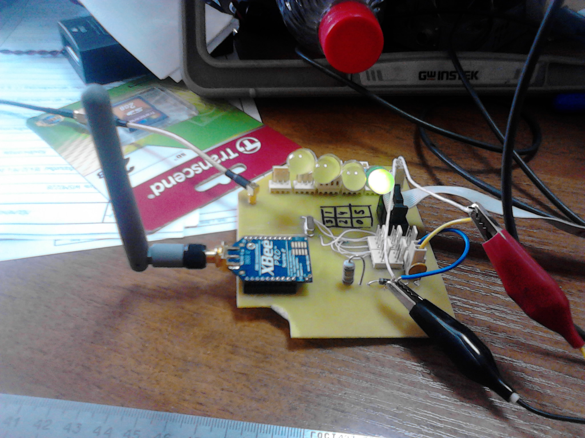
TSOP4038 receivers were used as infrared radiation detectors, which allow receiving a “continuous” modulated beam, unlike other series receivers, which, when a continuous beam is fed, simply “shut up” as a result of the built-in AGC and stop responding to any actions with the beam. For this receiver, an IR beam modulation frequency of 38 kHz is required, but experience has shown that this value is rather arbitrary, and a modulation frequency from 32 to 45 kHz is quite suitable for the task.
The emitting device is a TSAL6100 LED, powered by a modulating frequency generator. And placed roughly in the focus of the collecting lens.
About the emitter dwell in more detail. As I wrote earlier, the board in the photo is capable of processing up to 6 rays at a time. This is used to put the car on the start line in races with traffic lights. The so-called Pre-Stage, Stage and Start. To accurately position the car on the start line, a Stage beam is located 10-15 cm from the start beam. And when this beam crosses, the Stage indicator at the traffic light lights up, informing the participant about being on the start line and ready for the race.
At first glance, there is nothing complicated about this. But as practice has shown, it is impossible to place two LEDs just at a distance of 10-15 cm and not illuminate the "neighboring" sensor. That is, the task is the independent recognition of two rays traveling in parallel at a distance of 10-15 cm. Solutions: “mechanical” - focus the beam so that it only illuminates its sensor, “algorithmic” - think of something else.
Focusing the beam with the lens gives an excellent result, the spot size does not exceed 3-4 cm at a distance of 8 m, but there is one “but” - getting such a beam into the receiver is another task, especially when the beam is not visible, and about - 25 ° C. And besides, this aiming requires the use of mechanisms that implement the rotation of the emitter in two planes, which complicates the design itself.
The second variant is to focus the beam in one plane, which would require a cylindrical lens, but I did not find such a lens and I had to discard this option.
The third option is to split the rays in a different way. Namely - in time. Since we already have a source of accurate time signals (GPS) on the board, including each beam only at “our” moment in time, we can independently evaluate the presence or absence of a signal from each emitter. For this, a GPS receiver module was also installed in the emitter control circuit, which provided signal synchronization among themselves.
Such a solution made it possible to "expand" the beam, and pointing the emitter to the receiver was simplified by an order of magnitude.
As the focusing system, half of the cheapest optical sight was used (the price of the sight is in the region of 150-200 rubles), while the second half is used respectively for the second emitter.
Another nuisance is the exposure of the receiver to the sun, when the receiver was taken out into the bright sun, random triggering pulses were observed at its output, which led to false readings. The solution is a water pipe and food foil :)
Here's what it looks like. In the middle is a unit with receivers and a wireless module, along the edges are emitters.

Data transfer
As a wireless data network, it was decided to use something similar to Zig-Bee, namely, Xbee-Pro modules (actually this ZigBee is, with only some variations). Such modules allow you to deploy the network with minimal programming and configuration costs - in fact, they make the communication channel transparent from the serial interface of the transmitter to the receiver, and vice versa. Plus, the Pro version has an increased transmitter power, and, accordingly, the range. During the tests, it was possible to achieve stable operation at 500m, using standard D-Link pin antennas for Wi-Fi routers.
To transfer data to the computer, the Xbee-Usb adapter was assembled on the Xbee-Pro module and the FTDI232 chip.
How it works
A continuous timer synchronized with GPS is implemented in the receiver unit - the hardware timer of the microcontroller restarts by a 1PPS signal, which provides a fraction of a second countdown.
The signals from the IR receivers are connected to the external interrupts of the microcontroller. When the beam is interrupted, the current time value is captured and this “mark” is placed in the queue for transmission to the console.
Transfer to the console is carried out 1 time per second of all samples accumulated at the current moment. The panel confirms the reception of the count and the confirmed count is removed from the transmission queue.
Each sample has an identifier of the triggered signal and an identifier of the alignment on which the signal triggered.
The hardware work is done on this. Its task is to detect the moment of intersection of the beam and transfer this mark to the remote control.
Further, depending on the type of competition and the configuration of the race, the software comes into play.
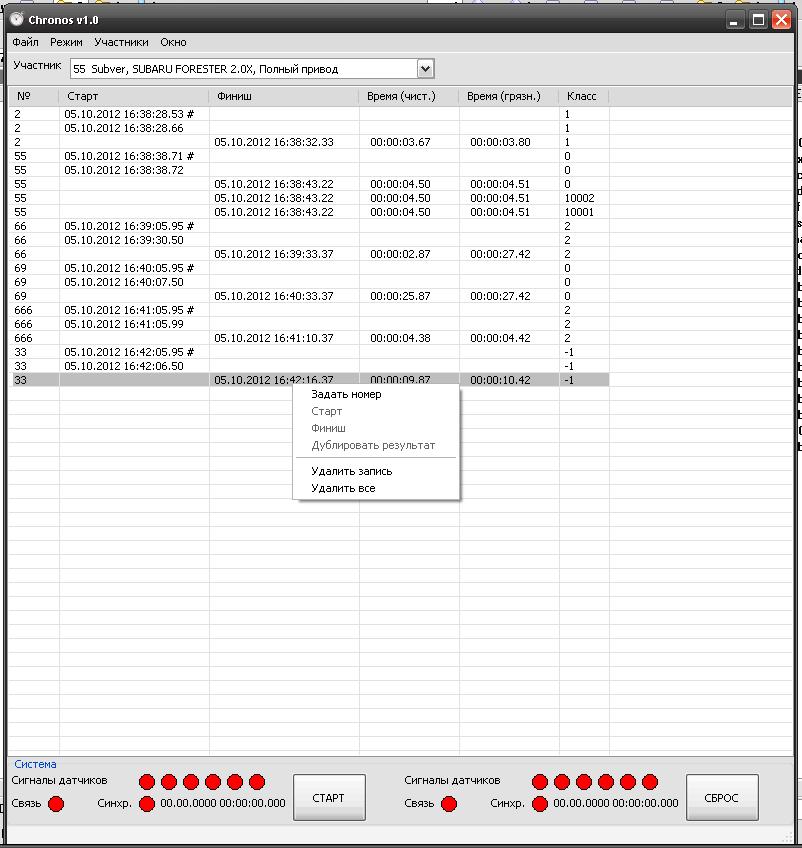
At the moment of receiving the count, a line with the accepted time stamp is displayed, depending on the source, this mark can be placed in the “Start” or “Finish” section, after which time is calculated for marks with the same number - time from start to finish, lap time, etc. .P.
If a false positive occurs (flying animals through the target, or pieces of inventory), the tag that has just got removed from the table does not affect the measurement results.
To ensure automation of calculation of results, each timestamp is assigned the number of the participant who passed through the target. This option allows timing, regardless of the number of cars on the track at the same time and their relative position.
The only option when the system does not work is to partially overlap the hulls when passing through one target.
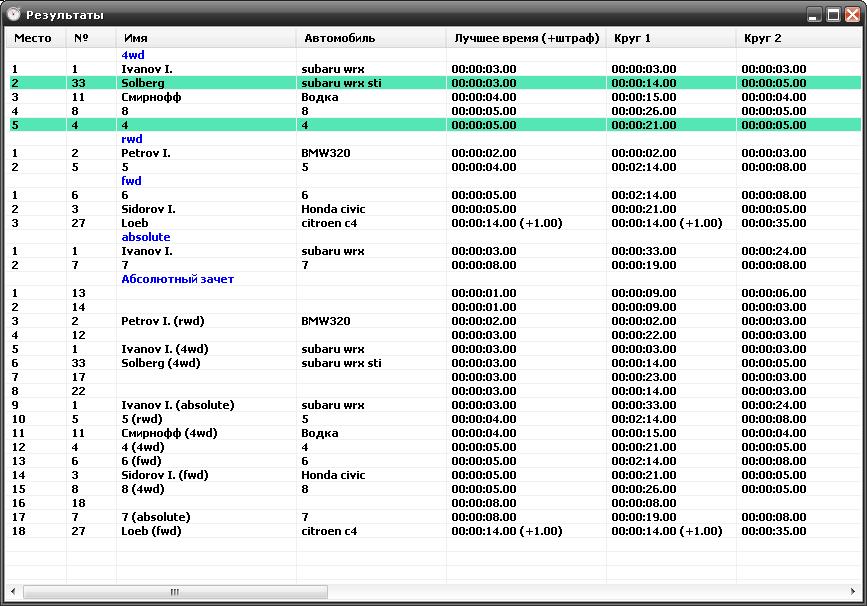
After assigning the number to the label, the results are recalculated and the final table is updated, which can be displayed on a separate large monitor for viewers.
For example, like that. This table is updated immediately after the participant passes the finish line, thus realizing an “online broadcast” of the results for the audience :)
Also, the software implements the ability to enter the data of each participant: start number, name, car model, class in which the athlete is declared. Based on the data in this table, the final list of competitions in automatic mode is formed.
Various modifications (in the process of evolution) of this system were used over the course of the year at several events, such as ice racing with a parallel start, dirt sprint with an interval start, and the Time Attack ring races. The system showed itself on the good side - compact design (a set on one target is placed in a package from the supermarket) and ease of operation.
At the 2nd Stage of Time Attack on July 27, 2013 in Omsk, an option was tested with the results displayed on a large monitor (or rather, TV :)) in real time. Spectators and competitors were satisfied).
The components from which the system was assembled:
- microcontrollers: ATMega8 (emitters), ATMega128 (receiving unit)
- GPS modules: Quectel L10
- wireless modules: Xbee Pro 2
- IR receivers: TSOP4038
- cases made of ABS plastic
- scrap metal stands
Results:
- accuracy of measuring the distance covered - not worse than 1ms (in the program it is rounded up to 0.01s for ease of perception)
- deployment time - 5-10 minutes
- operating time from a set of batteries - not yet determined, enough for a day, batteries - used 7A / h from an office UPS.
- the budget is approximately 5-6 thousand rubles. if I bought the parts myself, I used junk deposits at the workplace его
What else I wanted: this configuration requires the participation of an operator to enter the numbers of participants. It is necessary to somehow automate the identification of the participant who passed through the target.
For some time I became interested in amateur motorsport - no, not night street racing, but quite legal competitions held in the daytime and agreed with the relevant structures. As many people suspect, the purpose of such competitions is to drive the distance faster than the opponent. Why measure the distance.
The easiest way is to give the judges a stopwatch and teach them to press the Start / Stop button in time. The disadvantages of this method are obvious - unbearable low accuracy and suspicions of the participants about the bias of the judges. Another point - when conducting an amateur rally of the 3rd category, the start and finish are often spaced among themselves, and time is measured by the "synchronized" referee's clock. In practice, these are 30 r Chinese alarms that run away from each other for several seconds in 10 minutes.
A more modern way is the use of telemetry. The most common option is one or two alignments, triggered by the intersection of the IR beam, and at these intersections, control the stopwatch. The options I saw (amateur ones, we don’t take professional systems into account) left much to be desired and hoped for the best.
Example 1. A quarter mile race (402m), it is also Drag racing. At the start, an IR target with 2 or 3 pairs of rays is installed. At the finish line, a target with a pair of rays is also installed - one beam per track. A start traffic light is connected to the starting range. At the command of the controller, the traffic light begins the countdown of the starting sequence, after which the participants begin the race. The time is counted from the moment the green signal is ignited until the crossing of the finish line.
The logic and structure of such a system is obvious. A small minus is half a kilometer of wires connecting the start and finish target.
Example 2. Ring racing against the clock, the so-called Time Attack. Round trips, simultaneously at a distance of 2 participants. The result of the race is the participant’s lap time equal to the interval between successive passes of the alignment.
Everything is obvious too. Cons, I see the implementation:
- the need for each participant to pass only "their" target, which is indicated to him at the start, otherwise the system incorrectly calculates the lap times;
- in connection with the previous paragraph - finding part of the structure in the middle of the strip, which is fraught with consequences - often there were collisions on the central rack with the failure of the system;
- instability of the system to false alarms if a foreign object passes through the target, such as a downed cone, part of a fallen bumper, etc. Such a response led to the termination of the race, and a restart. And the participant was already driving on the “last money”, with a knocking motor and sought to win. It's a shame, yes.
Example 3. Rally-sprint, start and finish are spaced at a decent distance - on the order of hundreds or two hundred meters, participants start at intervals of 2-3 minutes, at a distance can be up to 7-10 cars at a time, depending on the length. The distance is measured by the actions of two judges - the judge at the start gives the start signal at a specific time by the clock, the judge at the finish - records the finish time according to his own clock, according to the difference in readings, the time is set off.
The disadvantages of this method of timing are the unsynchronism of the clock at the start and finish (as I wrote - Chinese alarms are often used from the stall in the transition), and the influence of the human factor (the judge at the start can release the car sooner or later, like the judge at the finish can to fix the moment of passage is not accurate enough).
At the next event, after listening to the complaints of the participants and organizers, I was asked to assemble the system for "my" requirements, for use in amateur motorsport competitions.
The requirements for this system were formed:
- Cheap. According to the organizers, the rental price of a semi-professional system reaches 15 thousand rubles. for the day of the competition - this option is clearly not for enthusiasts;
- The ability to adapt to various types of events - drag, ring, rally sprint, etc .;
- Ease of deployment and transportation - a minimum of parts, wires and other accessories;
- Maximum automation of the competition process - timing, arrangement of results and more.
In accordance with the aforementioned requirements, it was decided to implement a modular system with wireless information transfer, with the ability to process information on a PC and output the results to a printer or screen.
The modularity of the system is to create independent infrared targets that can be placed at a distance in an almost arbitrary configuration, at the start, at the finish, at the intermediate finish, etc.
Each target is able to record the time of the intersection of the beam and transmit the moment of fixation to the central console (the console is implemented on a laptop). The moment of fixation is a complete time stamp, including year, month, day, time, with an accuracy of 1 ms. Thus, having at our disposal information about the moments of crossing the alignment, we can algorithmically implement almost any scheme of arrival.
The only requirement in this embodiment is the exact synchronization of the cross-sections between themselves. Such synchronization is carried out using a GPS receiver - they are quite cheap at the moment and easy to use. The accuracy of synchronization without the use of special measures is up to 1 μs.
In the photo - an experimental board for the alignment, capable of processing up to 6 infrared rays at the same time, plus control of the starting traffic light. Why 6 rays? I will explain a little later.
TSOP4038 receivers were used as infrared radiation detectors, which allow receiving a “continuous” modulated beam, unlike other series receivers, which, when a continuous beam is fed, simply “shut up” as a result of the built-in AGC and stop responding to any actions with the beam. For this receiver, an IR beam modulation frequency of 38 kHz is required, but experience has shown that this value is rather arbitrary, and a modulation frequency from 32 to 45 kHz is quite suitable for the task.
The emitting device is a TSAL6100 LED, powered by a modulating frequency generator. And placed roughly in the focus of the collecting lens.
About the emitter dwell in more detail. As I wrote earlier, the board in the photo is capable of processing up to 6 rays at a time. This is used to put the car on the start line in races with traffic lights. The so-called Pre-Stage, Stage and Start. To accurately position the car on the start line, a Stage beam is located 10-15 cm from the start beam. And when this beam crosses, the Stage indicator at the traffic light lights up, informing the participant about being on the start line and ready for the race.
At first glance, there is nothing complicated about this. But as practice has shown, it is impossible to place two LEDs just at a distance of 10-15 cm and not illuminate the "neighboring" sensor. That is, the task is the independent recognition of two rays traveling in parallel at a distance of 10-15 cm. Solutions: “mechanical” - focus the beam so that it only illuminates its sensor, “algorithmic” - think of something else.
Focusing the beam with the lens gives an excellent result, the spot size does not exceed 3-4 cm at a distance of 8 m, but there is one “but” - getting such a beam into the receiver is another task, especially when the beam is not visible, and about - 25 ° C. And besides, this aiming requires the use of mechanisms that implement the rotation of the emitter in two planes, which complicates the design itself.
The second variant is to focus the beam in one plane, which would require a cylindrical lens, but I did not find such a lens and I had to discard this option.
The third option is to split the rays in a different way. Namely - in time. Since we already have a source of accurate time signals (GPS) on the board, including each beam only at “our” moment in time, we can independently evaluate the presence or absence of a signal from each emitter. For this, a GPS receiver module was also installed in the emitter control circuit, which provided signal synchronization among themselves.
Such a solution made it possible to "expand" the beam, and pointing the emitter to the receiver was simplified by an order of magnitude.
As the focusing system, half of the cheapest optical sight was used (the price of the sight is in the region of 150-200 rubles), while the second half is used respectively for the second emitter.
Another nuisance is the exposure of the receiver to the sun, when the receiver was taken out into the bright sun, random triggering pulses were observed at its output, which led to false readings. The solution is a water pipe and food foil :)
Here's what it looks like. In the middle is a unit with receivers and a wireless module, along the edges are emitters.
Data transfer
As a wireless data network, it was decided to use something similar to Zig-Bee, namely, Xbee-Pro modules (actually this ZigBee is, with only some variations). Such modules allow you to deploy the network with minimal programming and configuration costs - in fact, they make the communication channel transparent from the serial interface of the transmitter to the receiver, and vice versa. Plus, the Pro version has an increased transmitter power, and, accordingly, the range. During the tests, it was possible to achieve stable operation at 500m, using standard D-Link pin antennas for Wi-Fi routers.
To transfer data to the computer, the Xbee-Usb adapter was assembled on the Xbee-Pro module and the FTDI232 chip.
How it works
A continuous timer synchronized with GPS is implemented in the receiver unit - the hardware timer of the microcontroller restarts by a 1PPS signal, which provides a fraction of a second countdown.
The signals from the IR receivers are connected to the external interrupts of the microcontroller. When the beam is interrupted, the current time value is captured and this “mark” is placed in the queue for transmission to the console.
Transfer to the console is carried out 1 time per second of all samples accumulated at the current moment. The panel confirms the reception of the count and the confirmed count is removed from the transmission queue.
Each sample has an identifier of the triggered signal and an identifier of the alignment on which the signal triggered.
The hardware work is done on this. Its task is to detect the moment of intersection of the beam and transfer this mark to the remote control.
Further, depending on the type of competition and the configuration of the race, the software comes into play.
At the moment of receiving the count, a line with the accepted time stamp is displayed, depending on the source, this mark can be placed in the “Start” or “Finish” section, after which time is calculated for marks with the same number - time from start to finish, lap time, etc. .P.
If a false positive occurs (flying animals through the target, or pieces of inventory), the tag that has just got removed from the table does not affect the measurement results.
To ensure automation of calculation of results, each timestamp is assigned the number of the participant who passed through the target. This option allows timing, regardless of the number of cars on the track at the same time and their relative position.
The only option when the system does not work is to partially overlap the hulls when passing through one target.
After assigning the number to the label, the results are recalculated and the final table is updated, which can be displayed on a separate large monitor for viewers.
For example, like that. This table is updated immediately after the participant passes the finish line, thus realizing an “online broadcast” of the results for the audience :)
Also, the software implements the ability to enter the data of each participant: start number, name, car model, class in which the athlete is declared. Based on the data in this table, the final list of competitions in automatic mode is formed.
Various modifications (in the process of evolution) of this system were used over the course of the year at several events, such as ice racing with a parallel start, dirt sprint with an interval start, and the Time Attack ring races. The system showed itself on the good side - compact design (a set on one target is placed in a package from the supermarket) and ease of operation.
At the 2nd Stage of Time Attack on July 27, 2013 in Omsk, an option was tested with the results displayed on a large monitor (or rather, TV :)) in real time. Spectators and competitors were satisfied).
The components from which the system was assembled:
- microcontrollers: ATMega8 (emitters), ATMega128 (receiving unit)
- GPS modules: Quectel L10
- wireless modules: Xbee Pro 2
- IR receivers: TSOP4038
- cases made of ABS plastic
- scrap metal stands
Results:
- accuracy of measuring the distance covered - not worse than 1ms (in the program it is rounded up to 0.01s for ease of perception)
- deployment time - 5-10 minutes
- operating time from a set of batteries - not yet determined, enough for a day, batteries - used 7A / h from an office UPS.
- the budget is approximately 5-6 thousand rubles. if I bought the parts myself, I used junk deposits at the workplace его
What else I wanted: this configuration requires the participation of an operator to enter the numbers of participants. It is necessary to somehow automate the identification of the participant who passed through the target.