August 6, 2013 at 15:38
LED Flashing Stop Light for Arduino Pro Mini
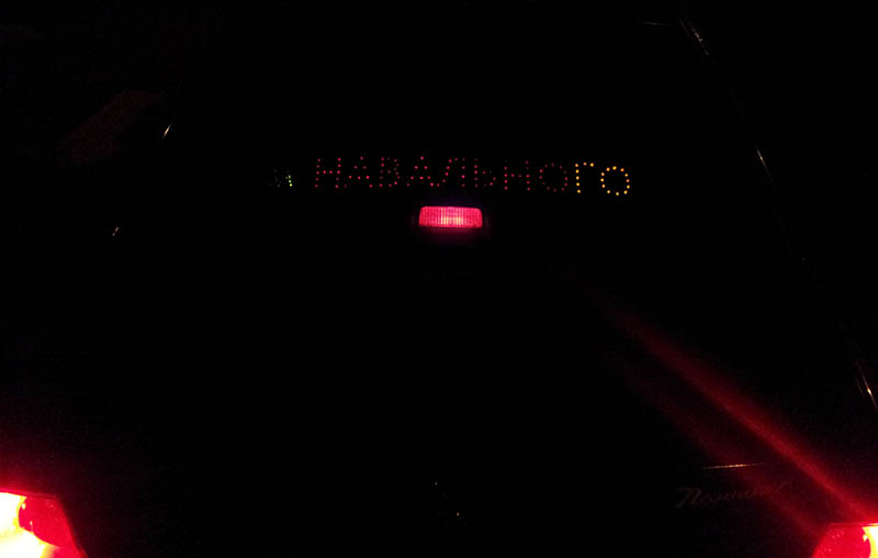
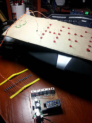 I just didn’t want to stick any stickers on the rear window of the car - it is not known who walks past the car at night and what will be the reaction to the inscription. It was decided to make an inscription with LEDs under the rear window. In inactive time it is not visible at all (tinted glass at the back), moreover, you can turn it off / on when needed. Well, a little later the idea came up to turn on the inscription only when the brake light comes on and make the inscription out of red LEDs - a simple duplication of the stop signal is obtained, but with additional information. All the work took 3 pm, that's what happened.
 Of course, you can just buy a running line or a light board and put it under the rear window ... But quickly after going over the prices of these devices, it immediately felt like a pity for the money and it was decided to do it yourself.
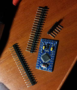
Firstly, I decided on the hardware - this is the Arduino Pro Mini, which costs $ 4 on eBay. Why exactly her? Because it is quite enough, even in abundance. It was planned to connect the LEDs to the PWM channels so that the brightness of the LEDs could be controlled. The Arduino Mini has only 6 of these outputs - that's enough for us. In fact, absolutely any Arduina is suitable for our task.
 Next, I decided on the inscription and broke it into 6 independent sections. This turned out to be a lot, so I left only 5 active ones and planned one channel for Prozapas. In each section, it turned out from 2 to 4 letters, for each letter about 10-20 LEDs are needed.
As you know, the Arduino output pulls only 40ma, because of this, connecting such a horde of LEDs directly to the Arduino outputs will not work. To solve the problem, the P16NF06 mosfets were used - powerful field workers, which I had 20 in my zashashnik. Of course, using mosfets for such a task is too much, because they can switch currents up to 1 ampere (for example, they pull quietly LED strip of good length). Instead, you can use simple bipolar transistors, which are cheaper. But mosfets can be connected directly to the Arduino pins, as they have a high input impedance and for the same reason they do not require a body kit in the form of resistor (s).
Then I had to allocate about 130 red 5mm LEDs from the stock. Unfortunately, I did not have so many red LEDs, so I had to make some letters green. As you know, LEDs need to be connected through a resistor to limit the current. It was decided to connect 6 pieces in series and already connect this block of LEDs through a resistor to + 12V. It was calculated and selected empirically that for 6 LEDs and a 12V supply voltage, a resistor of approximately 50 Ohms is needed.
The main points of the future device are indicated, now let's get down to business.
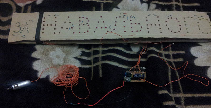
As a basis for the panel was taken ordinary cardboard from an old box. Two strips measuring 80x15 cm were cut. This size was optimal for placement under the rear window of the car. Then a text line was printed on the printer and a font for letters was selected - Calibri 300 in size. By applying it to the cardboard, the inscription was transferred to the strip. With tweezers, holes were made for the LEDs. Here it must be taken into account that the LEDs are connected in blocks of 6 pieces, so the number of LEDs multiple of 6 must be connected to each channel. In principle, this can be circumvented by creating a series of LEDs from any other quantity and calculating a resistor for connecting them to 12V.
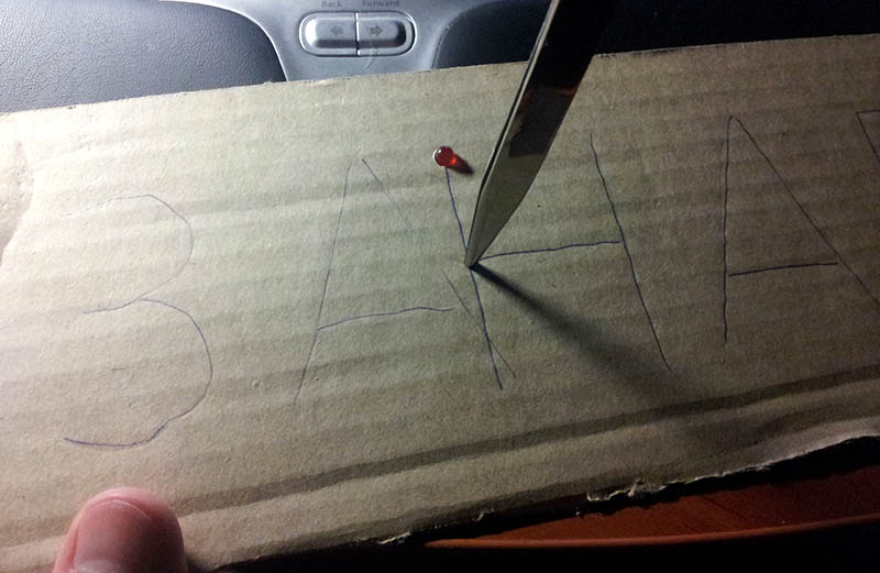
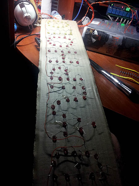
It was also very important for me to keep the legs of the LEDs intact, so that you can use them in other designs. Therefore, to connect the legs only slightly bent and soldered to each other. In short, the structure was assembled and soldered in about 3 hours.
The Arduino Mini is usually sold without legs, so the first thing to do is solder the legs to it. It turns out almost Arduino Nano, but only without 3.3V :)
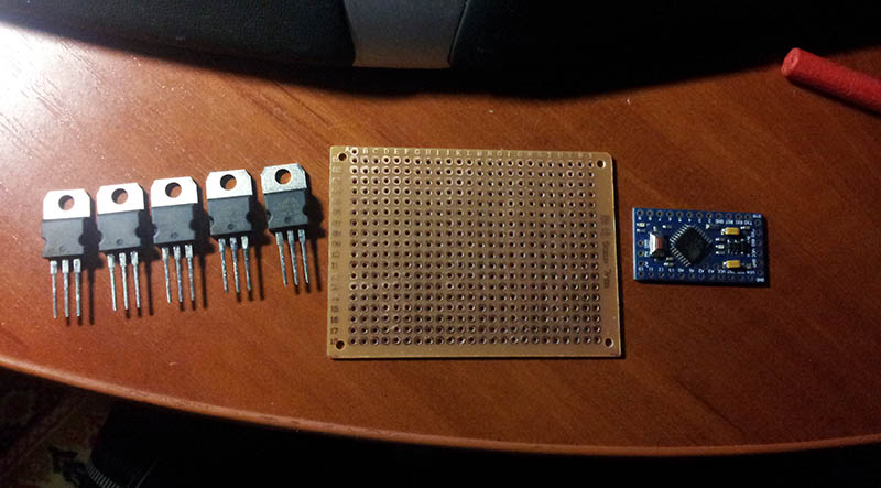
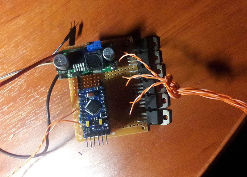
The connectors for inserting the controller board are also soldered to the breadboard. Then the mosfets are soldered so that a single heat sink can be screwed to them (although no heat sink is needed here, because very small currents). PWM pins 3, 5, 6, 9, 10, and 11 from the Arduino Mini are soldered to the corresponding inputs of the corresponding mosfet.

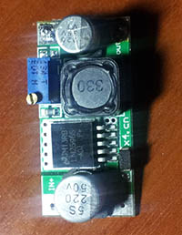 The next challenge was to provide the Arduino Mini with stable power. As you know, we have 12V from the car’s cigarette lighter, but this voltage may well be 13 and 14 volts at certain times when using the car. The Arduino Mini documentation says that the maximum supply voltage can be no more than 12V, and on the forum it was deducted that even a slight excess can disable the board. Therefore, it was decided to use a separate adjustable DC-DC regulator to power the Arduino. It can also be ordered on EBay (costs $ 1), but you can assemble it yourself. I have such blocks, so I used the ready one. Thus, 12V is supplied to a separate stabilizer (or even up to 30V), and the output is set to, say, 6V, which are fed to the RAW output of the Arduino Mini. The LEDs are powered directly from 12V (through mosfets).
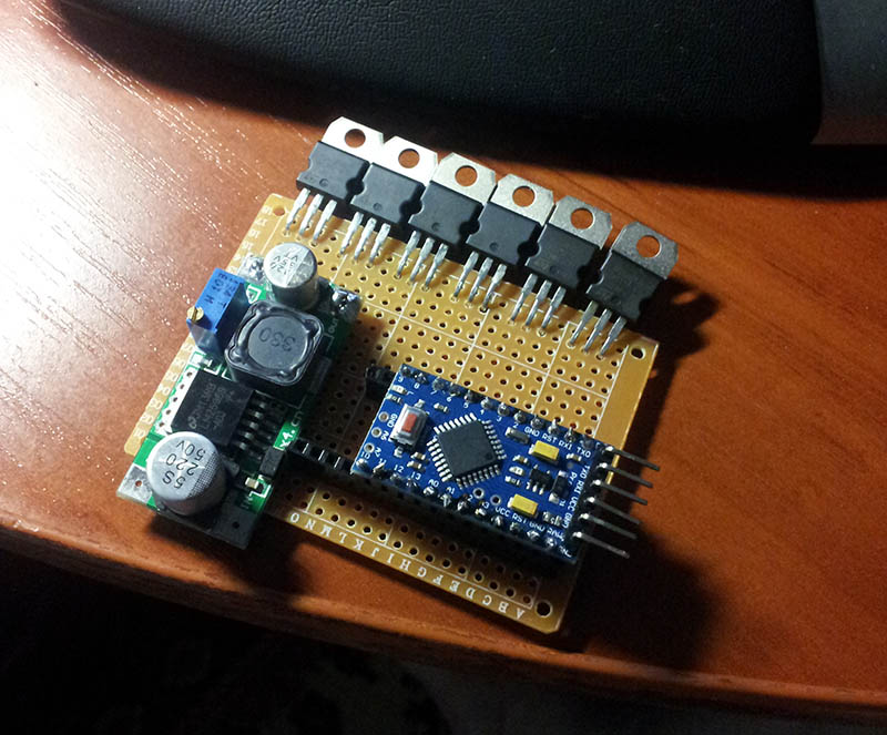
As a result of designing the printed circuit board in my mind, the following arrangement of elements turned out:
Now it is time to decide by which signal all this will turn on. At first, it was planned to connect the entire device directly parallel to the brake light on the car. But, unfortunately, when the voltage is applied to the Arduino, the controller is initialized and this lasts a rather long time> 1 sec. Moreover, immediately after switching on, the Arduino outputs are in the Z state and the mosfets react to this very randomly. As a result, after switching on, an arbitrary indication occurs during the entire initialization period of the controller. Of course, with the help of an additional body kit, you can set the initial state of the keys, but this requires more details and time ...
The second option was to connect the signal from the car brake light to the Arduino digital input. To do this, it was necessary to lower the voltage on the brake lamp to 5V, which, in principle, is not difficult. But this option turned out to be impractical due to the fact that it would have to unwind the rear panel and somehow connect to the brake light ...
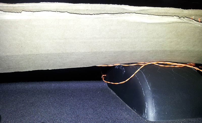
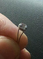 I wanted a completely simple solution and it was found! It was decided to use a simple photoresistor connected to the Arduino analog input. The photoresistor itself is simply placed in a box with a brake light. It turns out such a kind of opto-pair :) This solution allows you not to fit into the car's electrics at all. True, this is possible only when the brake light is in the cabin under the glass and our photoresistor can be inserted into it. In short, I have such access, so I did just that.
Moreover, the option with a photoresistor made it possible to solve another problem - the brightness of the glow, depending on the ambient light. Using a photoresistor, you can roughly estimate the illumination on the street and turn on the backlight brighter during the day, and dimmer at night. I took this into account in the program, although in practice it turned out that at night the LEDs do not blind behind the riders.
The photoresistor is connected to terminal A0 and to + 5V. A 10 kΩ resistor from terminal A0 to ground is also needed. The type of photoresistor and the resistor value in the divider affect the constants that will be set in the program (they can be selected experimentally).
The result is such a board:
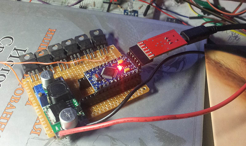
 Now let's get down to our favorite pastime - programming. In order to fill in the program in the Arduino Pro Mini, we need a USB Serial converter. I use FTDI Basic for this purpose, which can also be purchased on eBay.
 This is what the Arduino Pro Mini should look like before starting the firmware:
To do this, load the Arduino development environment. If everything is installed correctly, then the COM port should appear in the Tools / Serial Port menu. If it is not there, then you need to install the appropriate driver from the “drivers” folder of the platform itself.
After choosing a port, be sure to select Service / Board / Arduino Mini. Unfortunately, not everything is so simple here. Depending on the bootloader version, you may not be able to write the program to the controller. If, after compilation, a type error is generated
stk500_getsync(): not in sync: resp=0x00, then most likely the COM port speed of the development environment does not match the same parameter specified in bootloader. To fix this, it is recommended:
- Select Service / Board / Arduino Nano. This usually helps, but if it doesn’t work, then see the next paragraph.
- In the development environment folder we find the file "\ hardware \ arduino \ avr \ boards.txt". In this file we find the section "mini.name = Arduino Mini" and then the parameter "menu.cpu.mini.atmega328.upload.speed = 57600". Here we are trying to change the value of 57600 (you may have something else) to others. All possible speeds can be found in the monitor: menu Service / Port Monitor and here the selection is in the lower right corner. Before checking, you need to overload the development environment.
The program itself is hidden here
#define pinZA 3
#define pinNA 5
#define pinVAL 6
#define pinNO 9
#define pinGO 10
#define pinEMPTY 11
#define pinSTOPSIGNAL 0
#define sensValue 900 // порог включения. Значения 0-1024
#define sensNight 200 // ниже этого значения считается, что на дворе ночь. Значения 0-1024
#define lightDay 255 // Яркость днем. Значения 0-255
#define lightNight 150 // Яркость ночью. Значения 0-255
int currentMaxValueLight = 255;
void setup() {
  Serial.begin(9600);
  pinMode(pinZA, OUTPUT);  pinMode(pinNA, OUTPUT);  pinMode(pinVAL, OUTPUT);
  pinMode(pinNO, OUTPUT);  pinMode(pinGO, OUTPUT);
  setAll(0);
}
int currentEffect = 1;
int maxEffects = 2; // Всего эффектов в программе
void loop() {
  if(checkState()){
    switch(currentEffect){
      case 1: // Эффект 1
        effect_1();
        delayWithStateCheck(2000);
        effect_off();
      break;
      case 2: // Эффект 2
        effect_2();
        delayWithStateCheck(2000);
        effect_off();
      break;
      case 3: // Эффект 3... и тд.
         // ...................
      break;
    }
    currentEffect++;
    if(currentEffect > maxEffects){ // Больше нет эффектов, перематываем на первый
      currentEffect = 1;
    }
  }
}
void effect_2(){
  for(int i=0; i <= 1; i++){
    fade(pinZA, 3, true); fade(pinNA, 3, true); fade(pinVAL, 3, true); fade(pinNO, 3, true); fade(pinGO, 3, true);
    fade(pinZA, 3, false); fade(pinNA, 3, false); fade(pinVAL, 3, false); fade(pinNO, 3, false); fade(pinGO, 3, false);
    fade(pinGO, 3, true); fade(pinNO, 3, true); fade(pinVAL, 3, true); fade(pinNA, 3, true); fade(pinZA, 3, true);
    fade(pinGO, 3, false); fade(pinNO, 3, false); fade(pinVAL, 3, false); fade(pinNA, 3, false); fade(pinZA, 3, false);
  }
  setAll(currentMaxValueLight);
  delayWithStateCheck(200);
  setAll(0);
  delayWithStateCheck(100);
  setAll(currentMaxValueLight);
  delayWithStateCheck(200);
}
void effect_1(){
  fade(pinZA, 10, true);
  fade(pinNA, 10, true);
  fade(pinVAL, 10, true);
  fade(pinNO, 10, true);
  fade(pinGO, 10, true);  fade(pinGO, 3, false);  fade(pinGO, 3, true);  fade(pinGO, 3, false);  fade(pinGO, 3, true);
}
void effect_off(){
  fade(pinGO, 3, false);
  fade(pinNO, 3, false);
  fade(pinVAL, 3, false);
  fade(pinNA, 3, false);
  fade(pinZA, 3, false);
}
void fade(int pin, int d, boolean side){ // Включить/выключить с эффектом fade
  if(side){
    for(int value = 0 ; value <= currentMaxValueLight; value+=5){
      if(!checkState()) break;
      analogWrite(pin, value);
      delay(d);
    }
  }else{
    for(int value = currentMaxValueLight; value >=0; value-=5){
      if(!checkState()) break;
      analogWrite(pin, value);
      delay(d);
    }
  }
}
void delayWithStateCheck(int d){ // Задержка с проверкой не нужно ли выключать подсветку
  for(int value = 0 ; value <= d; value++){
    if(!checkState()) break;
    delay(1);
  }
}
boolean checkState(){ // проверка зажжен ли стоп-сигнал
  int val = analogRead(pinSTOPSIGNAL);
  boolean state = val > sensValue;
  if(!state){ // стоп-сигнал не горит
    setAll(0);
    if(val < sensNight){ // На дворе ночь или просто темно
      currentMaxValueLight = lightNight; // Уменьшаем максимальную яркость
    }else{
      currentMaxValueLight = lightDay; // Обычная яркость
    }
  }
  return state;
}
void setAll(int val){ // Установить все каналы в значение
  analogWrite(pinZA, val);
  analogWrite(pinNA, val);
  analogWrite(pinVAL, val);
  analogWrite(pinNO, val);
  analogWrite(pinGO, val);
}
The main "complexity" in the program is to bypass the standard delay function. The fact is that we need to turn off everything immediately after the brake light goes out. To do this, you must use either interruptions or constantly interrogate the illumination of the photoresistor. Because humanity has not yet come up with an analog input interrupt (either we need to make a kit and sew threshold values into the circuit), then we just use the home-made delayWithStateCheck function, which “crashes” when the stop signal goes out.
The result is as follows:
Ready device for installation:
Stop light with integrated photoresistor:
Night view:
Cost
All components were bought on eBay in China or Hong Kong in advance.
- Arduino Pro Mini - 150 rubles
- 6 pcs P16NF06 - 120 rubles
- 130 pcs LEDs - 90 rubles
- Photoresistor - 3 rubles
- DCDC Converter - 30 rubles
- Resistors 20 pcs - 10 rubles
- Wires from a pair of old Ethernet cable - 0 rubles
Total: 403 rubles.
conclusions
Good luck and success in the development of Arduino. Well, of course, do not lie or steal :)