June 10, 2013 at 16:30
The second chance or how I non-standard repaired the monitor
Recently, a friend of mine asked me to look at what's with his old monitor. By that time, the monitor had already stood under the table with a dead weight. Diagnosis - the monitor is not working. We connected it for the test to the system unit and it immediately showed its symptoms: the morrator dimly displays the image and goes out after 5 seconds.
There were several assumptions and one of them is that the high voltage inverter is buggy due to the drying of electrolytic capacitors. A little googling about this monitor (LG FLATRON L1752S), I found information about similar cases and similar problems. However, as it turned out, the output transistors can still fail there.
Taking the monitor home, I made a promise to see what was wrong with it and, if possible, fix it. Disassembling the monitor was not difficult (litter, did not take a picture of the process). A couple of plastic latches (around the perimeter of the case), a few unscrewed screws, and the guts appeared before my eyes: I will

immediately explain what and where in the photo. On the top left, on a cardboard box, lies the monitor matrix itself, under which I carefully placed the extruded polystyrene foam for safety. Top right is the back of the case, on which lies a board with buttons. Bottom left is the monitor backlight module. In it, as it turned out later, there were backlight lamps, a reflector made of organic glass and 3 pcs of frosted scattering films. Bottom right iron chassis on which lies the iron frame of the monitor with the upper part of the case and two boards.
Boards connect loops. The motherboard, the smaller one, is responsible for converting the received signal into an understandable matrix module. The board, the bigger one, the power supply for a smaller board, and also converts low voltage to high, to power the backlight. The first thing that caught my eye was the swollen electrolytic capacitors on the inverter board. Therefore, they were immediately replaced by good ones:
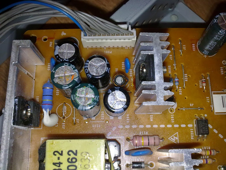
In the photo, new (I forgot to make a photo of the old) capacitors of black color near dark green. I connected the backlight of the monitor to the inverter and applied power to the inverter ...

... and the miracle didn’t occur naturally, the symptoms repeated (sorry for the quality of the photo and video - I shot it on an electric kettle):

Then I remembered the RTFM rule ("if something doesn’t work out for you, read this very fascinating manual"). First of all, I googled the inverter circuit of this monitor and began to study it for possible failures:

As it turned out, the inverter circuit has a protection that will stop the supply of high voltage if the backlight is not in order:


And then I realized that something was wrong with the lamps themselves (and I thought that once the subnet lights up - it means they are okay) and not with the inverter. I tried to “ring the cliff” with a tester - it turned out that they do not have a filament and do not ring at all. Carefully disassembling the backlight module, I was shocked - two of the four lamps (top) burned out. And not just burned, but even melted. At the same time, they “fried” the plexiglass reflector a little. The lamps were removed (forgot to take a picture) and immediately thrown into the trash.
I had to think about how to deceive the inverter protection so that it did not turn off the supply of high voltage to the surviving lamps. Logic suggested that you need to somehow load the inverter instead of a burnt out lamp. Technical education (not in vain 5 years studied) helped to find a solution. The solution was very original and at the same time very simple. As a load, 2kOhm resistors were used. Why exactly this and not other resistance you ask? I’ll answer - since I estimated that the voltage hardly exceeds 1000 V, the maximum current that will flow through the “snag” is not more than 0.5 A (according to Ohm's law):
1000 V / 2000 Ohm = 0.5 A
Having collected the test “snag”, turned on the monitor for a while ...


... and the backlight did not go out after 5 seconds. After waiting a couple of seconds, I turned off the power and touched the "trick" to the touch - it was cold, maybe I guessed with maximum load resistance. I decided to check the long-term mode of the robots - it turned out that the resistors were not warming at all:
It was not difficult to assemble the backlit matrix into a single whole and after turning on the joy there was no limit:

The inscription read “CHECK SIGNAL CABLE”, well, then I connected the cable and turned on the monitor again. Another inscription appeared - “POWER SAVING MODE” ...

... and the monitor went into standby mode (the backlight went out, the LED instead of blue turned yellow):

Everything is logical - there is no signal, and the monitor goes out. I connect the netbook and watch the image:

Scrolling the page does not fail, then the control board is whole. After that I checked the video display:

Also no glitches, the monitor is working correctly. I assemble the monitor (using the Blue Electrical Tape) back into the case, without forgetting to glue the "snag" on the wall of the case:

Test run after assembly:

The monitor chased for three hours and at the same time it worked perfectly. After a couple of days of running, the repaired monitor will return to the happy owner.
PS An article, typed at night, grammatical errors are possible, write where the error is and I will correct it.By the way, administrators (moderators) or who can - please pliz this post in "DIY or Do it yourself." Thanks. Many thanks, to the one who gave the invite, unfortunately I don’t know where to look at the name of this user, to mention him here ...
By the way, an interesting glitch was discovered during the trick test. When the subnet module and the boards were lying on the floor (laminate), and not on cardboard boxes, the backlight did not go out without a connected “snag”:
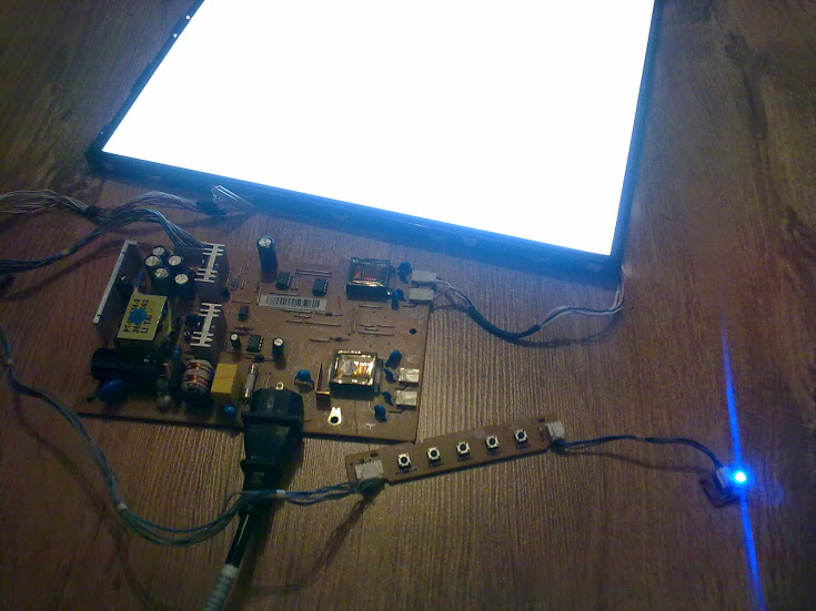
I think that the parasitic capacitive load influenced here, but how exactly it happened - I find it difficult to answer ...
PPS After the repair, I googled a very similar failure:
remont-aud.net/forum/23-19934-1
If anyone is interested in other possible damage to the monitor backlight, here some information:
shadowsshot.ho.ua/docs012.htm
By the way, here is another possible solution to the problems of burned backlight:
dung.com.ua/hardware/3376-led-podsvetka-monitora-svoimi-rukami-12-foto.html
There were several assumptions and one of them is that the high voltage inverter is buggy due to the drying of electrolytic capacitors. A little googling about this monitor (LG FLATRON L1752S), I found information about similar cases and similar problems. However, as it turned out, the output transistors can still fail there.
Taking the monitor home, I made a promise to see what was wrong with it and, if possible, fix it. Disassembling the monitor was not difficult (litter, did not take a picture of the process). A couple of plastic latches (around the perimeter of the case), a few unscrewed screws, and the guts appeared before my eyes: I will
immediately explain what and where in the photo. On the top left, on a cardboard box, lies the monitor matrix itself, under which I carefully placed the extruded polystyrene foam for safety. Top right is the back of the case, on which lies a board with buttons. Bottom left is the monitor backlight module. In it, as it turned out later, there were backlight lamps, a reflector made of organic glass and 3 pcs of frosted scattering films. Bottom right iron chassis on which lies the iron frame of the monitor with the upper part of the case and two boards.
Boards connect loops. The motherboard, the smaller one, is responsible for converting the received signal into an understandable matrix module. The board, the bigger one, the power supply for a smaller board, and also converts low voltage to high, to power the backlight. The first thing that caught my eye was the swollen electrolytic capacitors on the inverter board. Therefore, they were immediately replaced by good ones:
In the photo, new (I forgot to make a photo of the old) capacitors of black color near dark green. I connected the backlight of the monitor to the inverter and applied power to the inverter ...
... and the miracle didn’t occur naturally, the symptoms repeated (sorry for the quality of the photo and video - I shot it on an electric kettle):
Then I remembered the RTFM rule ("if something doesn’t work out for you, read this very fascinating manual"). First of all, I googled the inverter circuit of this monitor and began to study it for possible failures:
As it turned out, the inverter circuit has a protection that will stop the supply of high voltage if the backlight is not in order:
And then I realized that something was wrong with the lamps themselves (and I thought that once the subnet lights up - it means they are okay) and not with the inverter. I tried to “ring the cliff” with a tester - it turned out that they do not have a filament and do not ring at all. Carefully disassembling the backlight module, I was shocked - two of the four lamps (top) burned out. And not just burned, but even melted. At the same time, they “fried” the plexiglass reflector a little. The lamps were removed (forgot to take a picture) and immediately thrown into the trash.
I had to think about how to deceive the inverter protection so that it did not turn off the supply of high voltage to the surviving lamps. Logic suggested that you need to somehow load the inverter instead of a burnt out lamp. Technical education (not in vain 5 years studied) helped to find a solution. The solution was very original and at the same time very simple. As a load, 2kOhm resistors were used. Why exactly this and not other resistance you ask? I’ll answer - since I estimated that the voltage hardly exceeds 1000 V, the maximum current that will flow through the “snag” is not more than 0.5 A (according to Ohm's law):
1000 V / 2000 Ohm = 0.5 A
Having collected the test “snag”, turned on the monitor for a while ...
... and the backlight did not go out after 5 seconds. After waiting a couple of seconds, I turned off the power and touched the "trick" to the touch - it was cold, maybe I guessed with maximum load resistance. I decided to check the long-term mode of the robots - it turned out that the resistors were not warming at all:
It was not difficult to assemble the backlit matrix into a single whole and after turning on the joy there was no limit:
The inscription read “CHECK SIGNAL CABLE”, well, then I connected the cable and turned on the monitor again. Another inscription appeared - “POWER SAVING MODE” ...
... and the monitor went into standby mode (the backlight went out, the LED instead of blue turned yellow):
Everything is logical - there is no signal, and the monitor goes out. I connect the netbook and watch the image:
Scrolling the page does not fail, then the control board is whole. After that I checked the video display:
Also no glitches, the monitor is working correctly. I assemble the monitor (using the Blue Electrical Tape) back into the case, without forgetting to glue the "snag" on the wall of the case:
Test run after assembly:
The monitor chased for three hours and at the same time it worked perfectly. After a couple of days of running, the repaired monitor will return to the happy owner.
Link in a larger photo
PS An article, typed at night, grammatical errors are possible, write where the error is and I will correct it.
By the way, an interesting glitch was discovered during the trick test. When the subnet module and the boards were lying on the floor (laminate), and not on cardboard boxes, the backlight did not go out without a connected “snag”:
I think that the parasitic capacitive load influenced here, but how exactly it happened - I find it difficult to answer ...
PPS After the repair, I googled a very similar failure:
remont-aud.net/forum/23-19934-1
If anyone is interested in other possible damage to the monitor backlight, here some information:
shadowsshot.ho.ua/docs012.htm
By the way, here is another possible solution to the problems of burned backlight:
dung.com.ua/hardware/3376-led-podsvetka-monitora-svoimi-rukami-12-foto.html