Once again about delays in the source code of the FPGA project or a simple question for an interview for an FPGA developer job.
Some time ago, when discussing in a company of professional FPGA developers, a discussion arose about interviewing. What questions are asked there, and what could be asked. I suggested two questions:
- Give an example of a synchronous code without the use of delays, which will give different results when modeling and when working in real equipment
- Correct this code with delays.
After this question, a lively discussion ensued, as a result of which I decided to consider this issue in more detail.
I have already touched on this issue in a previous article . Now in more detail. Here is the text of the example:
library IEEE;
use IEEE.STD_LOGIC_1164.all;
entity delta_delay isend delta_delay;
architecture delta_delay of delta_delay issignal clk1 : std_logic:='0';
signal clk2 : std_logic;
alias clk3 : std_logicis clk1; -- назначение другого имени clk1signal a : std_logic;
signal b : std_logic;
signal c : std_logic;
signal d : std_logic;
begin--- Формирование тестовых сигналов ---
clk1 <= not clk1 after5 ns;
pr_a: processbegin
a <= '0'after1 ns;
waituntil rising_edge( clk1 );
waituntil rising_edge( clk1 );
a <= '1'after1 ns;
waituntil rising_edge( clk1 );
waituntil rising_edge( clk1 );
waituntil rising_edge( clk1 );
waituntil rising_edge( clk1 );
endprocess;
--- Синтезируемая часть - переназначение тактового сигнала ---
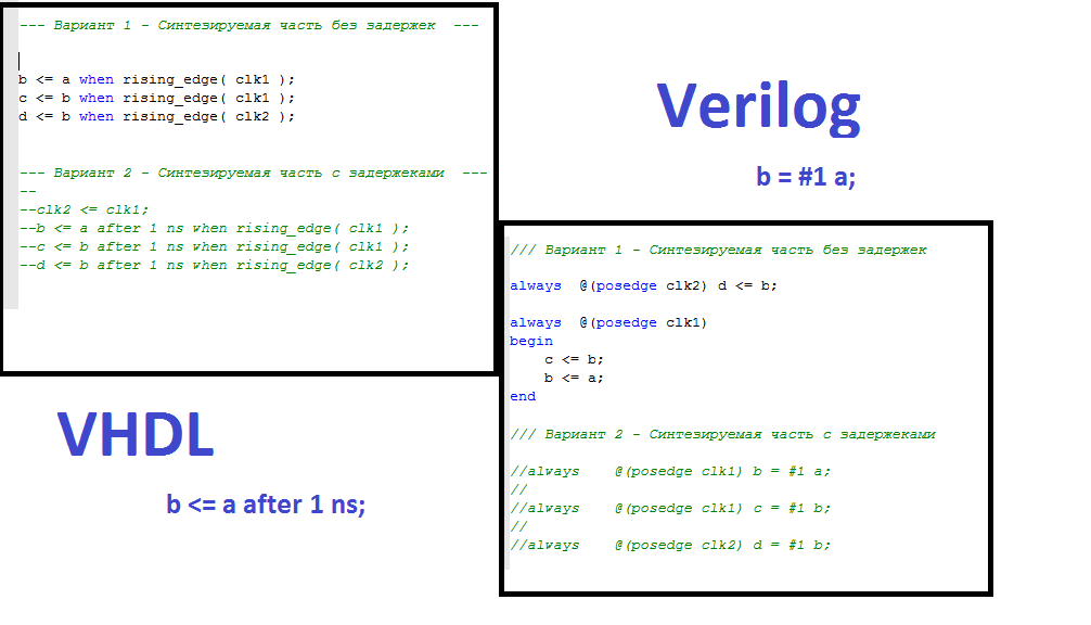
clk2 <= clk1; -- вот в этом проблема, не надо так делать без крайней необходимости--- Вариант 1 - Синтезируемая часть без задержек ---
b <= a when rising_edge( clk1 );
c <= b when rising_edge( clk1 );
d <= b when rising_edge( clk2 );
--- Вариант 2 - Синтезируемая часть с задержками -------clk2 <= clk1;--b <= a after 1 ns when rising_edge( clk1 );--c <= b after 1 ns when rising_edge( clk1 );--d <= b after 1 ns when rising_edge( clk2 );--- Вариант 3 - Синтезируемая часть без задержек но с переназначением сигнала через alias -----b <= a when rising_edge( clk1 );--c <= b when rising_edge( clk1 );--d <= b when rising_edge( clk3 );end delta_delay;
To simplify, all code is placed in one component.
The signals clk1 and a are test-action signals. clk1 is a clock frequency of 100 MHz, Signal a is held at two clock cycles at 0 and four clock waves at 1. Signal a is formed with a delay of 1 nc relative to the rising edge of clk1 . These two signals are enough to describe the problem.
Different versions of the synthesized code can be uncommented and modeled.
Consider the first option, this is a synthesized code without delay and using the reassignment of the clock frequency.
Here are the simulation results for option 1:

The diagram visually shows that the clock signalsclk1 and clk2 are the same, but in fact clk2 is delayed relative to clk1 by the delta delay value. Signal c lags the signal b by one clock cycle. It is right. But the signal d must coincide with the signal c , but this does not happen. It works before.
Let's remember what a delta is. This is a basic concept, it is based on the work of event simulators, which we use when modeling logic circuits.
The simulator has the concept of model time. All events in the system are tied to this model time. Let's look at the formation of the clock frequency:
clk1 <= not clk1 after5 ns;Suppose that now we are modeling only clk1 , there are no other signals.
At the initial time, clk1 is 0, which is set when the signal is declared. The simulator sees the requirement to invert the signal. The after keyword instructs you to assign a new value in 5 ns relative to the current model time. The simulator sees this and makes a mark that at the moment of time 5 ns the value clk1will be equal to 1. While this is a model future, by the way it may still change. Next, the simulator scans the other signals. The simulator will see that for the given moment of model time everything is done and he can calculate the next moment. The question arises - what time is next? In principle, different options are possible. For example, Simulink has a fixed pitch mode. In this case, there will be an increment of the model time by some amount and the calculations continue.
Digital circuit modeling systems do differently. They move to the next event, which they have already placed in the future on their own model time axis. In this case, it will be 5 ns. The simulator will see clk1changed and calculates a new value for it, it will be 0 which will also be placed with a delay of 5 ns on the time axis. Those. it will be a moment of 10 ns. And so the process will continue until the specified simulation time ends.
Now let's add signals a and b .
Signal a is assigned in process. For signal b , the conditional when construct is used; The rising_edge ( clk1 ) function analyzes clk1 and returns true when the front is fixed, i.e. the previous value is 0 and the current one is 1.
At the time of model time of 5 ns, clk1 will change. It will become equal to 1 and for the moment 10 ns an event of setting it to 0 will be created. But this later. While we are still at the moment of 5 ns and continue the calculations. Simulator goes to line
b<=a when rising_edge(clk1);b<=a;This is where the fun begins - when you need to change the value of b . It would seem necessary to change it now, at this moment in time. But we have parallel processes. Maybe we still need the value b to calculate other signals. And here comes the concept of delta delay. This is the minimum value by which the model time is shifted. This value does not even have the dimension of time. This is just a delta. But there may be many. And so much that the simulator just stops by mistake or freezes.
So, the new value of bwill be set to 5 ns + 1 (1 is the first delta delay). The simulator will see that there is nothing left to count for the moment of 5 ns and will proceed to the next moment, and this will be 5 ns + 1; At this point, rising_edge (ckl1) does not work. And the value of b will be set to 1. After that, the simulator will go to 10 nc.
Now let's add the signals c , d and see why they are different.
It is best to consider a model time of 25 ns, taking into account the delta delay
| delta | clk1 | clk2 | re (clk1) | re (clk2) | b | c | d |
|---|---|---|---|---|---|---|---|
| 0 | one | 0 | true | false | 0 | 0 | 0 |
| one | one | one | false | true | one | 0 | 0 |
| 2 | one | 0 | false | false | one | 0 | one |
Note: re - rising_edge
From the table it can be seen that at the moment when the rising_edge ( clk2 ) function is triggered , b is already equal to 1. And therefore, it will be assigned to signal d .
Based on common sense, this is not the behavior we expected from the code. After all, we simply reassigned the signal clk1 to clk2 and expected that the signals c and d would be the same. But following the logic of the simulator is not so. This is a fundamental feature. Of course, this feature should be known to developers of FPGA projects and therefore this is a good and necessary question for an interview.
What happens during the synthesis? But the synthesizer will follow common sense, it will make the signals clk2 and clk1 one signal and therefore c and d will also be the same. And with certain synthesizer settings, they will also be combined into one signal.
This is just the case when modeling and working in real equipment will lead to different results. I want to note that the reason for different results is the different logic of the simulator and synthesizer. This is a fundamental difference. This has nothing to do with time constraints. And if your project in the model and in the iron shows different results, then check, maybe a similar construction has crept in
clk2 <= clk1 Now the second question - correct this code with the help of delays.
This is option 2. It can be uncommented and modeled.
Here is the result.

The result is correct. What happened? Let's once again create a table for the interval 25 - 36 ns
| time | delta | clk1 | clk2 | re (clk1) | re (clk2) | b | c | d |
|---|---|---|---|---|---|---|---|---|
| 25 | 0 | one | 0 | true | false | 0 | 0 | 0 |
| 25 | one | one | one | false | true | 0 | 0 | 0 |
| 26 | 0 | one | one | false | false | one | 0 | 0 |
| 35 | 0 | one | 0 | true | false | one | 0 | 0 |
| 35 | one | one | one | false | true | one | 0 | 0 |
| 36 | 0 | one | one | false | false | one | one | one |
It can be seen that the value of b does not change at the moments of the clk1 , clk2 fronts . A delay of 1 ns leads the moment of signal change beyond the edge triggering zone. This code gets closer to reality. In a real circuit, there is some time for triggering a trigger and for signal propagation. This time should be less than the period of the clock frequency, which is, in fact, exactly what the tracer is trying to achieve and that is what the time analysis checks.
The cause of the error is the reassignment of the clock signal by the usual assignment at which the delta delay appears. However, the VHDL language has the alias construction. This allows you to get another name for the signal. Here is the announcement:
alias clk3 : std_logicis clk1;In the example text, you can uncomment option 3 - it will work correctly.
This example is written in VHDL. Could it be the problems of this language only? But here are the same options in the Verilog language.
Hidden text
`timescale 1 ns / 1 ps
module delta_delay_2 ();
reg  clk1 = 1'b0;
reg  clk2;
wire clk3;
reg a = 1'b0;
reg b;
reg c;
reg d;
initial begin
forever clk1 = #5 ~clk1;
end
initial beginrepeat(10)
begin#20 a = 1'b1;
#60 a = 1'b0;
endend// Синтезируемая часть - переназначение тактового сигнала  ---
always @(clk1) clk2 <= clk1;
// Вариант 1 - Синтезируемая часть без задержек
always 	@(posedge clk2)	d <= b;
always 	@(posedge clk1)
begin
	c <= b;
	b <= a;
end// Вариант 2 - Синтезируемая часть с задержеками  //always 	@(posedge clk1)	b = #1 a;	//	//always 	@(posedge clk1)	c = #1 b;		//	//always 	@(posedge clk2)	d = #1 b;			// Вариант 3 - Синтезируемая часть без задержек // но с переназначением сигнала через assign  //assign clk3 = clk1;		////always 	@(posedge clk3)	d <= b;			//	//always 	@(posedge clk1)//begin	//	c <= b;		//	b <= a;//end
endmodule
- Option 1 - without delay. It does not work correctly.
- Option 2 - with delays. Works correctly.
- Option 3 - reassigning via wire. Works correctly.
Verilog has reg and wire. In this case, reassigning the clock signal through wire looks more natural. This is analogous to the assignment via alias in the VHDL language. This somewhat relieves the tension of the problem, but you still need to know.
Also in the Verilog language there is the concept of blocking and non-blocking assignment. The purpose of signals b and c can be written differently:
always 	@(posedge clk1)
begin
	c = b;
	b = a;
end
And you can:
always 	@(posedge clk1)
begin
	b = a;
	c = b;
end
Depending on the row order, the result will be different.
Returning to the topic of the interview, I want to stress once again that these questions are about understanding the essence of the problem. And from the understanding of the problem one can draw different conclusions, for example, which style of code to use. Personally, I always use destination delays.
Sample files are available here.
Only registered users can participate in the survey. Sign in , please.