A little about the manufacturing process of electronic devices
Good afternoon, dear habrachitateli.
I have always been interested in industrial automation, this is a world of robots and precise actions. But unfortunately, this world is rather closed; it’s quite difficult to get into the working workshop of the enterprise, especially the automated one. Now I work with a Russian electronics manufacturer (I will not advertise), and I want to share with you knowledge and photos of the electronics manufacturing workflow.
I apologize for the quality of the photo, only a soap dish is available.
Under the cut a lot of pictures. Caution! traffic
I will omit the boring details of the development process of the board itself. The author comes up with a scheme, breeds in a picade or altium, and orders a fee at one of the Russian plants. We do not work with the Chinese, due to constant failure to meet deadlines (due to customs) and jambs of boards (fees are later changed, but their delivery time becomes six months or more).
Then the board multiplies. That is, the PCB sheet is filled with copies of the board so that the final size is close to the maximum. Board separation lines are usually asked to scribe (cut from 2 sides to a shallow depth). Despite the incision of the board it is very difficult to break with your hands, they are cut on a special machine.
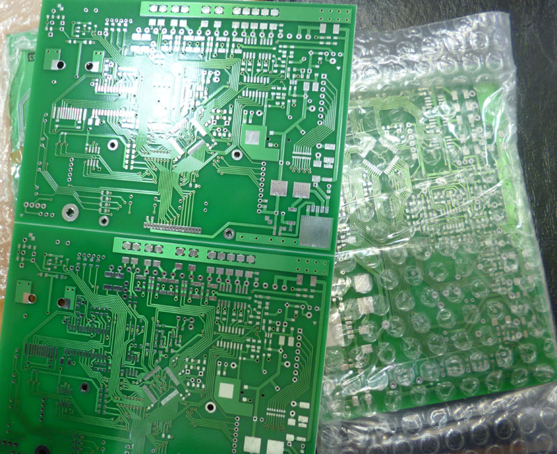
Figure 1. Boards It is
necessary to replicate a board to reduce labor input and increase production speed, since many operations are done simultaneously.
Production is divided into 2 parts. SMD section, and a surface mounted installation.
The process of soldering SMD is as follows. A special paste is applied to the board, which is a mixture of finely ground solder and flux. Next, the machine places the parts on this paste, and then the board goes to the stove, from where it comes out already with the soldered parts.
And now in detail about the process. In order to spread the paste only on the right places, a stencil is ordered. This is a thin sheet of tin, in which the windows are cut through with a laser, in places where the elements will be soldered.
The stencil is clamped in a special frame that stretches it so that it is smooth and does not bend (the stencils are very thin, from 0.18 mm). Stretched by pneumatics. An air duct is laid along the edge of the frame, like a camera from a wheel, which, when pressure is applied, stretches itself and stretches the frame. Next, a board is placed under the stencil, a strip of paste is squeezed out on top, and a special scraper is carried out 1 time so that the paste passes and fills all the holes.
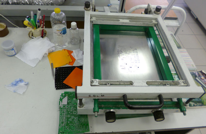
Figure 2. A stencil in a frame.
Smearing pasta is a very responsible process. It is important to precisely align the board with the holes, and smear it with a strictly defined force, otherwise the paste is pressed under the stencil and spreads, and these are closed adjacent legs and marriage. Some boards smear 2-3 times (especially if there are chips with frequent steps), erase, smear, wash, smear, and so on until you get the perfect option.
There is a mess on the table because now the frame is idle. But you can see a jar of pasta (this tiny jar weighs half a pound), and a bottle of alcohol that erases the paste if it is poorly spread.
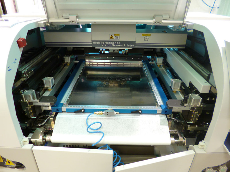
Figure 3. Machine for spreading paste.

Due to the huge loss of time when spreading the paste, this machine was bought here. Dadada, this huge colossus is simply stenciling the squeegee ... and that’s it =). Well, or almost everything. It made a conveyor, 2 boards in line at the input, 2 at the output. And a 2D control system that analyzes that the paste is spread correctly and there are no empty spots anywhere.
Figure 4. Pasta spreading machine, inside view.
Here is his picture inside. You can see the frame with the stencil (it is pulled out), the blue lace to the stencil, this is air (for tension). In front of the frame there is a roller with special fabric (the second end of the strip of fabric on the roller somewhere below), the machine wipes the stencil from the bottom with this fabric. In the back of the machine, 2 squeegees glisten, with which he smears the paste. The paste is manually squeezed onto the stencil. Below is a special camera looking through a translucent prism simultaneously up and down. It is needed to combine the reference points on the stencil and on the board (in order to match all the holes on the stencil with the soldering points on the board).
The operator refills the stencil, squeezes a thick strip of paste onto it. Loads the program for the desired board (the machine changes the width of the conveyor and finds out where to look for reference points) closes the lid, and starts feeding the board to the conveyor input. At the output, it receives the boards smeared evenly and neatly and puts them in a special container.
Next, you need to place the components on the SMD board. This is a separate machine, which we will consider in more detail.
SMD components are supplied in tapes. The tape is placed in the feeder, a special device that unpacks the component, and allows the machine to conveniently take it.
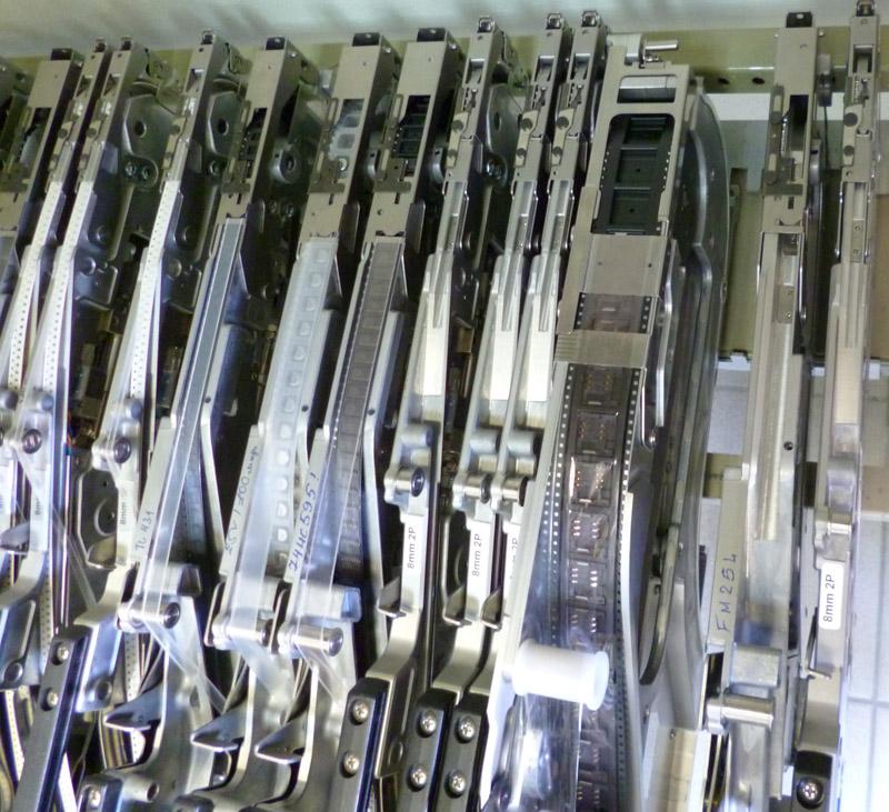
Since the tape is fed into the feeder for a rather long time, there are much more feeders than it can fit into the machine, and in their free time they are in such a shelf.
Figure 5. Shelf feeders.
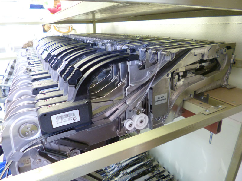
Figure 6. Feeder top view.
I would also like to consider microcircuits. They come in 2 types of packaging, pallets (multi-legged, with legs on 4 sides), and in plastic rulers.
Figure 7. Pallet with microchips.
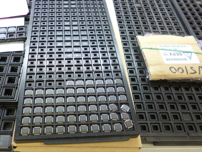
For pallets there is a special table where it is attached with clamps.
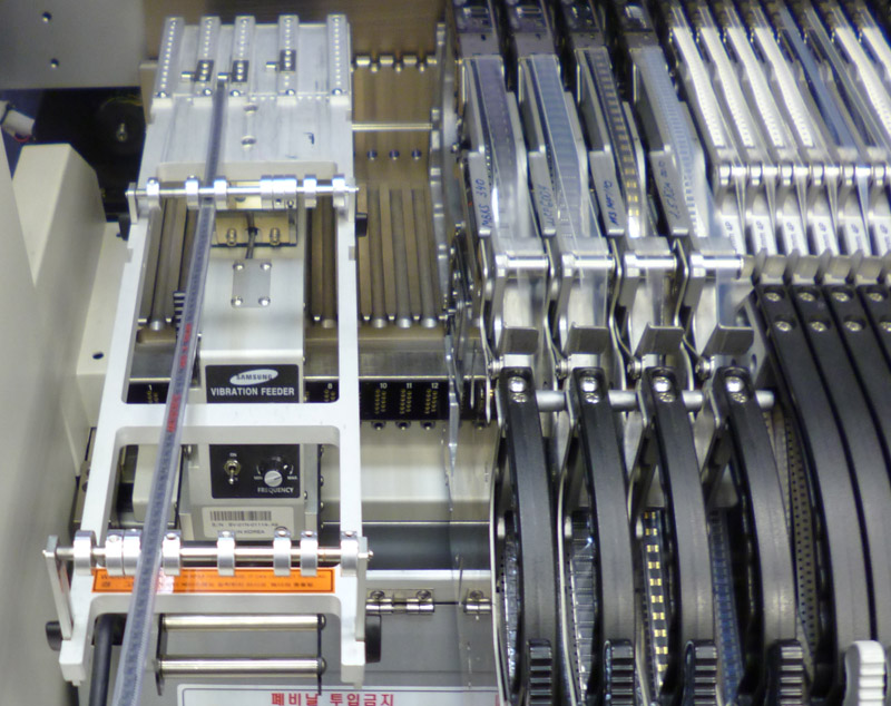
For the plastic line, a special tricky feeder is placed. The line in it is fixed in the guides, a limiter is placed at the bottom, which allows only one microcircuit to travel, and this whole structure vibrates so that the microcircuits automatically slide down.
Below you can see the vibration enable knob, and the intensity settings.
Figure 8. Feeder for microchips.
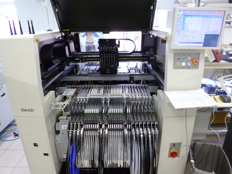
The machine is pneumatic, and requires a huge amount of extra clean air. It is powered by a medical compressor, which costs 3 times more expensive than my car.
Figure 9. General view of the SMD machine.
Let's move on to the machine itself.
The “program” is loaded into the machine (the local file name with the board parameters), the dimensions of the board are written in it, where which element is located, which nozzle to take it, and at what speed.
Figure 10. The head of the SMD machine.
Elements are arranged by a head on which there are 6 pneumatic suction cups. The suction cups have interchangeable nozzles, they can be seen in the photo, they are to the right of the head. Behind the head you can see a piece of the pallet table with microcircuits, and feeders on the back of the machine.
At the table with nozzles you can see a square window, inside it there is a backlight and a camera. There, the machine aligns the microcircuit (they do not always lie smoothly).
The amount of pneumatics and cables is awesome.
Figure 11. Air supply to the head.
Feeders are connected to the places marked with numbers. Inside there is an electronics that detects jamming and ending of the tape.
Figure 12. Feeders in the machine.
This is the predecessor of a large machine (we have 3 of them), it is rarely used, since the new machine works about 4 times faster. The old machine processes a board of 170-200 components in 20-30 minutes, a new one in 5-8.
Figure 13. Small SMD machine.

After all the elements are installed by the machine, the operator visually checks that there are no shifted or rotated parts, and sends the board to the furnace.
Figure 14. The stove, a general view.
There are 7 zones in each of which the desired temperature is set. The zones are separated by air knives (similar in principle to a thermal curtain at the outlet in shopping centers). The furnace profile consists of zone temperatures, and conveyor speed. The furnace automatically calculates how many boards it soldered, and shows the position of the boards on the conveyor.
An incorrectly configured profile threatens with soldering (if the massive components do not have time to warm up), or a shift of the elements (if the solder has been melted too much and for too long).
Figure 15. Stove, settings screen.

After the stove, the board passes visual inspection. I will skip the automated control system, since its training and work on it is a separate large article.
Then the board goes to the hinged assembly workshop, where the hinged elements are soldered in the old fashioned way.
In general, work in production opens up problems that I have not thought of before.
1. Air is a very valuable resource. Industrial equipment eats it at a frantic speed, and there are no compressors that can provide such a volume. (building a compressor station is incredibly expensive). Moreover, the equipment requires ultra-clean air, conventional compressors will not work.
2. Board layout is an art. When soldering with a soldering iron, you can breed as you want. When soldering SMD, inaccurate wiring leads to problems. The components are so light that they simply float away in the oven if you bring a thick path to the soldering place (tightens with a surface tension of the solder), the video inspection system trips over all the places where the solder is slightly more or less than normal, and the pads should strictly correspond to the size of the element.
3. Any hinged component is a huge brake in production, as the machine solders much faster than people. It is often more profitable to put a SMD capacitor for 6 rubles, instead of the usual one for 30 kopecks, but to avoid getting the board in the wall mounting. Otherwise, just do not have time to produce the desired volume.
That's all. Unfortunately, I can’t (I can’t) upload a video of a working machine, this is the most bewitching sight.
I hope you enjoyed my mini tour.
I have always been interested in industrial automation, this is a world of robots and precise actions. But unfortunately, this world is rather closed; it’s quite difficult to get into the working workshop of the enterprise, especially the automated one. Now I work with a Russian electronics manufacturer (I will not advertise), and I want to share with you knowledge and photos of the electronics manufacturing workflow.
I apologize for the quality of the photo, only a soap dish is available.
Under the cut a lot of pictures. Caution! traffic
I will omit the boring details of the development process of the board itself. The author comes up with a scheme, breeds in a picade or altium, and orders a fee at one of the Russian plants. We do not work with the Chinese, due to constant failure to meet deadlines (due to customs) and jambs of boards (fees are later changed, but their delivery time becomes six months or more).
Then the board multiplies. That is, the PCB sheet is filled with copies of the board so that the final size is close to the maximum. Board separation lines are usually asked to scribe (cut from 2 sides to a shallow depth). Despite the incision of the board it is very difficult to break with your hands, they are cut on a special machine.
Figure 1. Boards It is
necessary to replicate a board to reduce labor input and increase production speed, since many operations are done simultaneously.
Production is divided into 2 parts. SMD section, and a surface mounted installation.
The process of soldering SMD is as follows. A special paste is applied to the board, which is a mixture of finely ground solder and flux. Next, the machine places the parts on this paste, and then the board goes to the stove, from where it comes out already with the soldered parts.
And now in detail about the process. In order to spread the paste only on the right places, a stencil is ordered. This is a thin sheet of tin, in which the windows are cut through with a laser, in places where the elements will be soldered.
The stencil is clamped in a special frame that stretches it so that it is smooth and does not bend (the stencils are very thin, from 0.18 mm). Stretched by pneumatics. An air duct is laid along the edge of the frame, like a camera from a wheel, which, when pressure is applied, stretches itself and stretches the frame. Next, a board is placed under the stencil, a strip of paste is squeezed out on top, and a special scraper is carried out 1 time so that the paste passes and fills all the holes.
Figure 2. A stencil in a frame.
Smearing pasta is a very responsible process. It is important to precisely align the board with the holes, and smear it with a strictly defined force, otherwise the paste is pressed under the stencil and spreads, and these are closed adjacent legs and marriage. Some boards smear 2-3 times (especially if there are chips with frequent steps), erase, smear, wash, smear, and so on until you get the perfect option.
There is a mess on the table because now the frame is idle. But you can see a jar of pasta (this tiny jar weighs half a pound), and a bottle of alcohol that erases the paste if it is poorly spread.
Figure 3. Machine for spreading paste.
Due to the huge loss of time when spreading the paste, this machine was bought here. Dadada, this huge colossus is simply stenciling the squeegee ... and that’s it =). Well, or almost everything. It made a conveyor, 2 boards in line at the input, 2 at the output. And a 2D control system that analyzes that the paste is spread correctly and there are no empty spots anywhere.
Figure 4. Pasta spreading machine, inside view.
Here is his picture inside. You can see the frame with the stencil (it is pulled out), the blue lace to the stencil, this is air (for tension). In front of the frame there is a roller with special fabric (the second end of the strip of fabric on the roller somewhere below), the machine wipes the stencil from the bottom with this fabric. In the back of the machine, 2 squeegees glisten, with which he smears the paste. The paste is manually squeezed onto the stencil. Below is a special camera looking through a translucent prism simultaneously up and down. It is needed to combine the reference points on the stencil and on the board (in order to match all the holes on the stencil with the soldering points on the board).
The operator refills the stencil, squeezes a thick strip of paste onto it. Loads the program for the desired board (the machine changes the width of the conveyor and finds out where to look for reference points) closes the lid, and starts feeding the board to the conveyor input. At the output, it receives the boards smeared evenly and neatly and puts them in a special container.
Next, you need to place the components on the SMD board. This is a separate machine, which we will consider in more detail.
SMD components are supplied in tapes. The tape is placed in the feeder, a special device that unpacks the component, and allows the machine to conveniently take it.
Since the tape is fed into the feeder for a rather long time, there are much more feeders than it can fit into the machine, and in their free time they are in such a shelf.
Figure 5. Shelf feeders.
Figure 6. Feeder top view.
I would also like to consider microcircuits. They come in 2 types of packaging, pallets (multi-legged, with legs on 4 sides), and in plastic rulers.
Figure 7. Pallet with microchips.
For pallets there is a special table where it is attached with clamps.
For the plastic line, a special tricky feeder is placed. The line in it is fixed in the guides, a limiter is placed at the bottom, which allows only one microcircuit to travel, and this whole structure vibrates so that the microcircuits automatically slide down.
Below you can see the vibration enable knob, and the intensity settings.
Figure 8. Feeder for microchips.
The machine is pneumatic, and requires a huge amount of extra clean air. It is powered by a medical compressor, which costs 3 times more expensive than my car.
Figure 9. General view of the SMD machine.
Let's move on to the machine itself.
The “program” is loaded into the machine (the local file name with the board parameters), the dimensions of the board are written in it, where which element is located, which nozzle to take it, and at what speed.
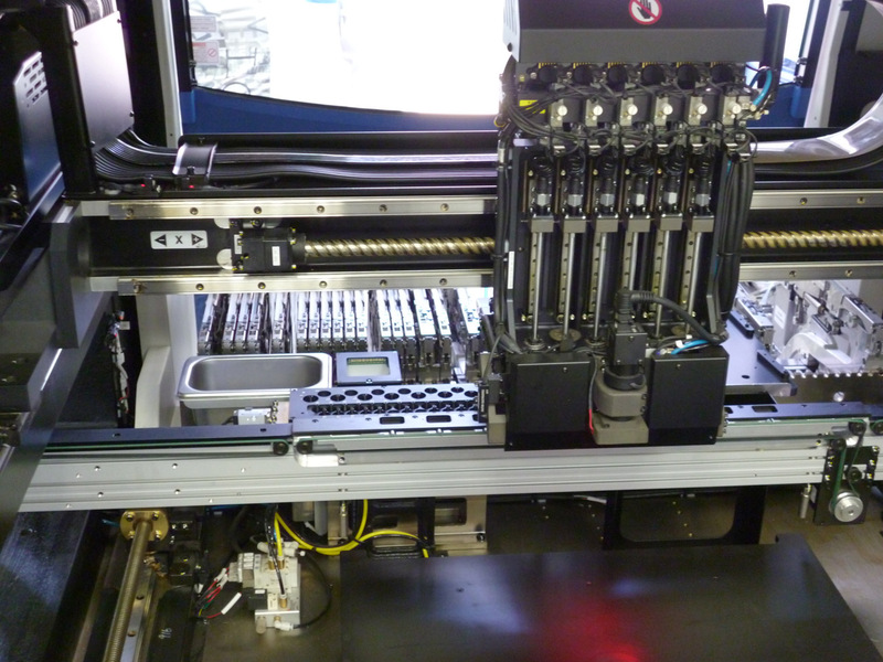
Figure 10. The head of the SMD machine.
Elements are arranged by a head on which there are 6 pneumatic suction cups. The suction cups have interchangeable nozzles, they can be seen in the photo, they are to the right of the head. Behind the head you can see a piece of the pallet table with microcircuits, and feeders on the back of the machine.
At the table with nozzles you can see a square window, inside it there is a backlight and a camera. There, the machine aligns the microcircuit (they do not always lie smoothly).
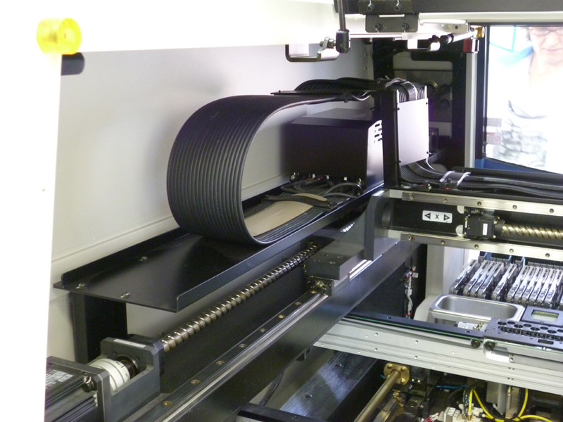
The amount of pneumatics and cables is awesome.
Figure 11. Air supply to the head.
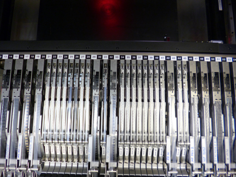
Feeders are connected to the places marked with numbers. Inside there is an electronics that detects jamming and ending of the tape.
Figure 12. Feeders in the machine.
This is the predecessor of a large machine (we have 3 of them), it is rarely used, since the new machine works about 4 times faster. The old machine processes a board of 170-200 components in 20-30 minutes, a new one in 5-8.
Figure 13. Small SMD machine.
After all the elements are installed by the machine, the operator visually checks that there are no shifted or rotated parts, and sends the board to the furnace.
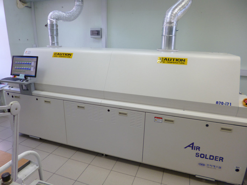
Figure 14. The stove, a general view.
There are 7 zones in each of which the desired temperature is set. The zones are separated by air knives (similar in principle to a thermal curtain at the outlet in shopping centers). The furnace profile consists of zone temperatures, and conveyor speed. The furnace automatically calculates how many boards it soldered, and shows the position of the boards on the conveyor.
An incorrectly configured profile threatens with soldering (if the massive components do not have time to warm up), or a shift of the elements (if the solder has been melted too much and for too long).
Figure 15. Stove, settings screen.
After the stove, the board passes visual inspection. I will skip the automated control system, since its training and work on it is a separate large article.
Then the board goes to the hinged assembly workshop, where the hinged elements are soldered in the old fashioned way.
In general, work in production opens up problems that I have not thought of before.
1. Air is a very valuable resource. Industrial equipment eats it at a frantic speed, and there are no compressors that can provide such a volume. (building a compressor station is incredibly expensive). Moreover, the equipment requires ultra-clean air, conventional compressors will not work.
2. Board layout is an art. When soldering with a soldering iron, you can breed as you want. When soldering SMD, inaccurate wiring leads to problems. The components are so light that they simply float away in the oven if you bring a thick path to the soldering place (tightens with a surface tension of the solder), the video inspection system trips over all the places where the solder is slightly more or less than normal, and the pads should strictly correspond to the size of the element.
3. Any hinged component is a huge brake in production, as the machine solders much faster than people. It is often more profitable to put a SMD capacitor for 6 rubles, instead of the usual one for 30 kopecks, but to avoid getting the board in the wall mounting. Otherwise, just do not have time to produce the desired volume.
That's all. Unfortunately, I can’t (I can’t) upload a video of a working machine, this is the most bewitching sight.
I hope you enjoyed my mini tour.