My version of the "device for lucid dreaming" - a brief history and description of the first version
Note: The article is written solely for informational purposes, and is not a call to repeat such experiments at home due to the potential risk of harm to physical health (in the case of use of Li-ion batteries and photoresistors in the devices).
Good day, dear habouriors and habwearers) This is my first serious article on Habré, therefore, JUDGE MOSTLY STRICTLY, I promise to work on style and content.
Briefly about yourself. By education - instrument maker, master. Occupation: entrepreneur, I am a co-founder of the network of robotics robots for children’s circles. During his studies at the university he was engaged in various kinds of research in the field of medical measuring equipment.
Long time was going to talk about these of their developments, but all hands did not reach ...
Prehistory Since childhood, I have often seen very vivid and plot dreams. So plot and vivid that he was not lazy from the age of seven with enviable persistence to keep a diary of dreams. And then, once, back in 2014, I got into the hands of a curious book called Dream Hackers. Do I have to say how much I was interested in the phenomenon around which the story lined up? Especially when taking into account the diary, which has exceeded in the amount of 2 notebooks of 96 sheets each, and since 2012 it has been running on a computer.
A quick googling, after a significant anti-esoteric filtering, led me to scientific studies on sabzh. As it turned out, the beginning of the study of the OS in the first half of the 20th century was put by a certain Dutch psychologist, Frederick Van Eden. His article, “A Study of Dreams” (Proceedings of the Society for Psychical Research, vol. 26, p. 431), which aimed to classify dreams, contained the term “lucid dreams”, which literally translates to “clear dreams”. As far as I know, this was the first mention of this phenomenon in scientific circles.
Years passed, but only in 1975, an experiment scientifically proved the existence of an operating system was carried out by the scientist Keith Hearne, Hull (England) University's sleep-laboratory. As a result of the experiment, experimental Alan Worley showed conscious and pre-planned eye movements when, in all indications of the instruments, he was in a state of sleep. This experiment was later rerun by scientist Stephen Laberge of Stanford University.
The results of the experience became widely known, since Laberge made a huge contribution to the popularization of this subject. Also, this scientist proposed a concept of a device called the “inducer of lucid dreams,” which would allow anyone, even without a long workout, to enter the OS state ...
After I read about the OS inductor, I could not sleep anymore. Arduinschik soul inflamed incredible tide of enthusiasm! The fact is that by that time I had already read a lot about various kinds of practices that allow me to realize in a dream, and all of them didn’t give any results without long training sessions and work on myself. And dreaming to steer something, hunt!)
Having studied the whole variety of OS inductors with which the market was dazzled, as well as the base of homemade products, of which there were also many on the Web, I sketched a standard, the essence of which was reduced to the following wording: “do not Remee, but closer to Dreamstalker but more convenient. " Technical requirements boiled down to these four points:
- The device must reliably determine the phase of fast sleep (and not “guess at NE555”, as it was, judging by the descriptions, in early versions of the Remee mask);
- The device should be compact and should not interfere with the sleep process;
- The device must be able to collect and display information about the sleep process in order to conduct real research, and not just play in the OS;
- The device must be safe to use.
Such are the requirements ... Nehilo for someone who at that time barely touched the basics of working with operational amplifiers, and generally poorly versed in circuit design) However, "young-green", and I began to develop.
To begin with, I decided to take up the simplest question: what physiological parameters change during sleep? The result of the search was such a table (if anyone can add - write in the comments, I will be very happy):

Solid knowledge of the school course in biology and physics, along with moderate programming skills in C ++ and LabVIEW, as well as possession of some information from the field of measuring equipment , allowed me to develop a block diagram of the device. She looked like this:

The logic was as follows. In order not to fence the measuring laboratory on the forehead of a person (and not to become like a working, but terribly inconvenient Dreamstalker mask), all measuring blocks from the mask should be removed. Moreover, the found schemes of optical oculographs were either too complicated or extremely cumbersome. And how to register an oculogram, you ask? After all, eye movements in a dream are the most reliable sign of REM sleep!
Well, then I decided that once the heartbeat is also changing in some way, then it will be possible to find the phase of rapid sleep and on it. Thus, a device appeared in the device, with a pulse sensor on board. And only the radio receiver unit and a handful of LEDs remained in the mask, which were supposed to be switched on by a command from a computer.
The logical question is: why is there a computer, and why it was impossible to immediately send commands from the bracelet when it would detect the necessary changes in heart rhythm? Firstly, I did not know which changes to consider as “necessary”. Moreover, at the time, the person’s pulse graph of what a cardiointervalogram and heart rate variability look like is generally weak ... Secondly, various complex algorithms in a graphical development environment are much simpler and clearer to write, and finding the right sleep phase by heartbeat is clearly simple algorithms are not relevant, and therefore - LabVIEW to help.
Circuit
Mask:
- Platform Arduino Micro Pro (on ATmega32U4 stone)
- LEDs WS2812B
- Standard radio receiver module with 433 MHz carrier frequency
- Li-ion 200 mAh battery
- Charging module for battery on TP4056 microcircuit
In order of the choice of components. The Micro Pro platform was chosen because of its compactness (due to the lack of CH3400 and the presence of built-in PLL and USB, but this is the lyrics), as well as low power consumption and just a pleasant appearance.
I chose the addressable RGB LEDs because I wanted to see if the frequency of hits in the OS would not correlate with the color of the stimulating effect. I know that sounds so-so, but who knows, right?)
I chose the 433 MHz module for two reasons: because I hadn’t tried anything else from the wireless connection, and because I didn’t know what a colossal pig this module would fit me ... When it came to tests, it turned out that the antenna was meticulously measured, sewn along the contour of the mask, being close to the body, cannot work in principle. As I was explained in the “Radio Amateur” group, to which I sometimes ask questions, due to the fact that the human body has a certain capacity, which is quite significant, and because of this, the receiver frequency is lost, as there is an oscillating circuit in it, and an extra capacity hinders him. I do not understand everything, I don’t want to be dishonored, I can only say that at that time I couldn’t conduct experiments with a mask.
I chose the battery because of its compactness, having sacrificed a safety requirement: a lithium ionnik attached to the nose, although it had a small capacity, could have damaged the eyes during an explosion. Therefore, as best I could, I packed it in plastic from the side adjacent to my face and left open the opposite side. This did not affect the compactness of the design, but added peace of mind, albeit unjustified.
With the charging module, everything is simple: it is almost the industry standard for all sorts of home-made products, and here I was not steamed about anything.
Bracelet:
- Arduino Nano Platform
- Homemade optical pulse sensor (more about it will tell later)
- Standard radio transmitter module (same 433 MHz)
- Holder for four AA
- 4 Ni-Mh battery at 2700 mAh each
With the bracelet, things were better. I collected the first version directly on the breadboard, and the antenna of the transmitting module did not fit directly to the body, therefore everything worked like a clock. The only thing that deserves attention in the first version of the bracelet is the pulse sensor, which was perhaps my biggest problem, since I swam in analog electronics.
A very good article about photoplethysmography and how different bracelets for fitness are arranged has become a foothold. After reviewing the essence of the work of optical pulse sensors, I began to look for ready-made circuit solutions. As a result, I stopped at this scheme, which earned almost immediately even on breadboard. I didn’t look for an open channel optocoupler recommended by the author of the article, and simply tore the TCRT5000 out of the line sensor, which was accidentally left lying at home. I replaced the operational amplifier with the more common LM358.
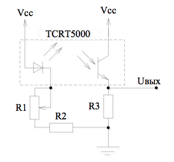
The sensor was made in the form of a ring, put on the pad of the finger. The TCRT5000 was pressed tightly against the skin, and the signal from the phototransistor was amplified and transmitted by wire to the microcontroller, where it was digitized and sent further along the instances.
Transmitting unit:
- Arduino Nano Platform
- Standard radio receiver module with 433 MHz carrier frequency
- Standard radio transmitter module (same 433 MHz)
Everything is trivial: when the bracelet sends data, it is received by the receiver, and through the COM port sharashat into the computer, where they are met by the caring paws of my samopisny VI. The first version of the virtual device stupidly built the ADC readings graph, and did not try to analyze anything by itself. Subsequently, when it became more or less clear that it was necessary to analyze not the pulsogram, but the intervalogram built on it, and the patterns that often arise in the BDG phase were identified, data began to be sent from VI to the mask, giving a signal to activate the stimulation. But until that moment it was still very far away))
The first night with a heart rate monitor revealed several unpleasant facts.
First: due to the fact that in a dream the blood flow in the hand changes (for example, when I bend my arm and stay in this position for a long time), the sensor loses the signal and the graph becomes illegible. I had no idea how to adjust the gain automatically.
Second, the sensor could lose a signal on a flat spot, and a very low-frequency interference with a very large amplitude is superimposed on the graph itself, due to which it disappears at times. Below is a screen of the testimony of one of the first (but not the first) working versions of the virtual instrument. Pulsogram graph (red) is inverted, and low-frequency noise can be seen on the lower peaks.

The third fact: to sleep with a breadboard model and four batteries on your hand is not at all impossible, but extremely uncomfortable. How it looked at first, you can see below (alas, except for photos from the diploma, nothing remains of that sketch)))

"Serious improvements are needed!" - looking at the messy data, I concluded with harsh cabbage soup. And first of all I decided to finish the sensor, which was needed first of all to continue working on the device.
Once again, after rereading the article on photoplethysmographs, I realized the following: why the hell
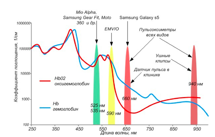
Based on the graph, I chose green as the most absorbed by hemoglobin in both its states (saturated with oxygen and unsaturated). Therefore, the sensor will become the most sensitive to changes in blood volume, and not to saturation with its oxygen (I suspected that I had a low-frequency disturbance because the sensitivity of the IR sensor changes significantly due to oxygen saturation of the blood).
Under the spoiler: I wonder if it is impossible to track the respiratory rate just for this low-frequency noise?
And everything would be fine, but here's the plug: what to choose as a sensitive element? After a brief search, I found a cheap option - a photoresistor. The advantages were obvious: the spectral peak of the most common models, just around 500 nm, is cheap, and its inertia, which is often reproached, is not significant in this case - the heartbeat itself is not very fast.
Of the minuses, I noted for myself only that photoresistors contain cadmium and lead (which is why in some countries they were banned altogether), and it is not very good to use them in equipment that is in direct contact with the body. But - science requires sacrifices, and I bungled the second version of the sensor: on two address LEDs (the wavelength of their green color was, according to the datasheet, just the way it was needed). A plus was the fact that now it was possible to change the brightness programmatically, thus adjusting the sensitivity, albeit within small limits.

As you can see, the illiterate (but minimally working) filtering and amplifying circuit remained in its place, and the sensor now has already got two wires to connect with the MC.
When the layout was assembled, the tests showed a significant improvement in the measurement results. Although the sensor could not work “on reflection” (I wanted to make the bracelet a full bracelet, but it did not work out - the reflected signal was too weak), but it worked perfectly well for the light. Also, the low-frequency interference went away, which put an end to signal loss.
The development of the device entered a new stage - now all efforts were directed at collecting data and trying to find the desired sleep phase among them.
But about this - in the next article, and then later now, and you can’t disturb the sleep mode)
PS I’m freeing the readers, I’ll post in the public domain all the schemas and sources of the project so that the bytes are not covered with dust on my hard drive.
Any utility:
- the book "Clear Sleep Skills", which is the most complete collection of scientific information on sabzh;
- the coolest homemade product with open source from all that I saw
- a cool selection of virtual instruments for analyzing biomedical signals