Embedded architecture design

Good day! I would like to talk about the architecture of embedded applications. Unfortunately, there are very few books on this topic, and due to the fact that, recently, interest in embedded and IoT is growing, I would like to pay attention to this issue. In this article, I would like to describe one of the possible options for how you can design such applications.
This is a debatable question! Therefore, they offer to share their vision in the comments!
To begin with, let's define the area: in this article, under embedded development, we mean software development under microcontrollers (hereinafter referred to as MK, for example STM32) in C / Asm.
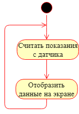
Projects for systems based on the MK can be divided into not requiring and requiring multitasking. As for the solutions of the first type, they are usually not very complex (from a structural point of view). For example, a simple project in which it is necessary to read data from a sensor and show it on the screen does not require multitasking; here it is sufficient to implement the sequential execution of the listed operations.
If the application is more complicated: within the framework of which it is necessary to read data from both digital sensors and analog ones, save the obtained values in memory (for example, to an sd card), serve the user interface (display + keyboard), provide access to data through digital interface (for example, RS-485 / Modbus or Ethernet / TCP / IP) and quickly respond to certain events in the system (pressing the emergency buttons, etc.), in this case it will be difficult to do without multitasking. There are two ways to solve the problem of multitasking: implement it yourself, or use some kind of operating system (hereinafter OS). Today, one of the most popular real-time operating systems for embedded systems is FreeRTOS.
Let's try to imagine how the architecture of a “complex” embedded application that performs a fairly large number of heterogeneous operations should look like. I admit that it is possible to propose an even more complex variant, which involves solving the problems of sound processing, cryptography, etc., but let us dwell on the variant that was described a little higher.
We set the task more clearly, even though within our application it is necessary:
- Read data from sensors on the RS-485 / Modbus bus.
- Read data from sensors on the I2C bus.
- Read data from discrete inputs.
- Manage relay output.
- Serve user interface (display + keyboard).
- Provide access to data on the RS-485 / Modbus bus.
- Save data to external media.
Because we need to implement a sufficiently large number of different subtasks; we will use a real-time operating system (for example, the above-mentioned FreeRTOS) as a base. Threads in the OS will sometimes be called tasks - by analogy with FreeRTOS. I just want to warn you: the source code in the article will not be, the architectural aspect of this issue is interesting.
If you analyze the task, you can see that different components of the system use the same data. For example: data from the sensors must be obtained, displayed on the screen, written to the media and provided to external systems for reading. This suggests that we need some kind of real-time database (RTDB) for storing and for providing the most up-to-date data to various subsystems.
Tasks performed in the system (data read, write, display, etc.) may have different requirements for the frequency of their call. It makes no sense to update the data on the display with a frequency of 1 time in 100 ms, because this is not critical for a person, but it is often necessary to read data from sensors (especially if it is necessary to issue control actions on them) (although it may not depending on the TK). Another important point is related to the solution of the problem of access to the same data for reading and writing. For example: the stream polling the sensors writes the received values to RTDB, and at this point the stream responsible for updating the information on the display reads them. Here we will be helped by the synchronization mechanisms provided by the operating system.
Let's start designing the architecture of our application!
Real time database

As such a base can be a regular structure containing the required set of fields or an array. To access “RTDB”, we will use an API that will allow us to write and read data from the database. Synchronization of access to data within API functions can be built on the mutexes provided by the OS (or use some other mechanism).

Work with sensors on tires
Working with sensors implies the following:
- reading data;
- data processing (if necessary), which includes:
- validation check;
- scaling;
- filtering;
- checking for valid values;
- write the received data to RTDB.
All this work can be done in one task.
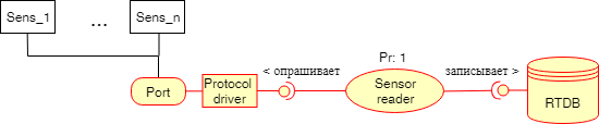
“Port” - real port of MK;
“Protocol driver” - protocol driver (for example, Modbus). By such a driver, it is desirable to make your interface and work through it. Within the framework of such an interface, it is possible to implement access control to the resource through mutexes, as this was done for “RTDB”. Some developers propose to do this at the port level in order to be sure that no one else will write anything to this port while we send our Modbus packets through it.
“Sensor reader” - the task (task), which polls the sensors, arranges the received information and writes it to “RTDB”.
“RTDB” is the real-time database described above in the corresponding section.
The inscription “Pr: 1” above a task means priority, the bottom line is that each task can have a priority, if two tasks that have processor time, a different priority, a resource that has a higher priority. If tasks have the same priority, then the one that has a longer wait time will start.
Work with discrete inputs
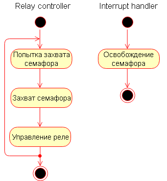
In general, work with discrete inputs can be organized just as with digital sensors. But it may be necessary to respond quickly to changes in the state of the inputs. For example, by pressing a button as soon as possible to close the relay output. In this case, it is better to apply the following approach: for processing the relay output, we create a special separate task with a higher priority than the others. Inside this task is a semaphore, which it is trying to capture. An interrupt is triggered to trigger a particular discrete input, in which the semaphore mentioned above is reset. Because the interrupt priority is maximum, then the function associated with it will be executed almost instantly, in our case, it will reset the semaphore, and after that, the next task in the queue for execution will be the one
This is how the scheme of this subsystem may look like.

In addition to quickly triggering a change in the state of a specific input, you can optionally set the “DI reader” task to read the status of discrete inputs. This task can be either independent or caused by a timer.
The work of “Interrupt handler” and “Relay controller” in the form of diagrams is presented below.
Write data to external media
Writing data to external media is ideologically very similar to reading data from digital sensors, only the movement of data is carried out in the opposite direction.
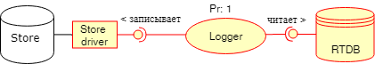
We read from “RTDB” and write it through “Store driver” to external media - this can be an SD card, USB flash drive or something else. Again, do not forget to put a mutex wrapper (or any other tools for organizing access to the resource) in the interface function!
Providing access to real-time data
An important point is the provision of data from “RTDB” to external systems. It can be almost any interfaces and protocols. Unlike the number of considered subsystems, the key difference is that some of the protocols widely used in automation systems impose special requirements on the response time to the request, if the answer does not come within a certain time, it is considered that there is no such device communication, even if he (the answer) comes after a while. And since access to “RTDB” in our example may be temporarily blocked (by the mutex) it is necessary to provide for the protection of an external master device (master is a device that tries to read data from ours) from such a lock. It is also worth ensuring the protection of the device itself from the fact that the master will interrogate it with great frequency, thus slowing down the work of the system by constant reading from "RTDB". One solution is to use an intermediate buffer.
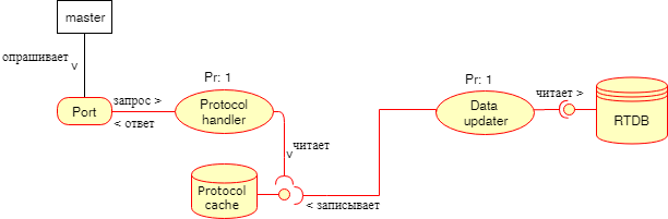
The “Data updater” reads data from “RTDB” at specified intervals and adds what it read into “Protocol cache”, from which “Protocol handler” will take data. In this case, there is a blocking problem at the level of the protocol cache, to solve it, you can create another cache in which the “Protocol handler” will store data in case you could not read from the blocked “Protocol cache”, you can also:
- do it for “ Protocol handler ”higher priority;
- increase the reading period from “RTDB” for “Data updater” (which is so-so solution).
Work with user interface
Working with the user interface involves updating the data on the screen and working with the keyboard. The architecture of this subsystem may look like this.

The UI worker is engaged in reading keystrokes, retrieving data from “RTDB” and updating the display that the user sees.
General system structure
Now take a look at what happened in the end.

In order to balance the load, you can put additional caches, as we did in the subsystem responsible for providing data access to external systems. Part of the task of transferring data can be solved with the help of queues, since they are usually supported by real-time operating systems (exactly).
That's all, I hope it was interesting.
PS
As a literature, I would advise “Making Embedded Systems: Design Patterns for Great Software” Elecia White and Andrei Kurnitz’s article “FreeRTOS - an operating system for microcontrollers”