Google Glass. Start
Google glass. Certainly an interesting gadget that opens a new page in consumer electronics. Necessary or not, perhaps complex, unreliable and has little battery life, but it is the first and there is no arguing with that. Or not the first ... because the idea did not come out of thin air - I’ll try to trace the evolution of the development of such devices that can combine an external real image with an additional, virtual one.
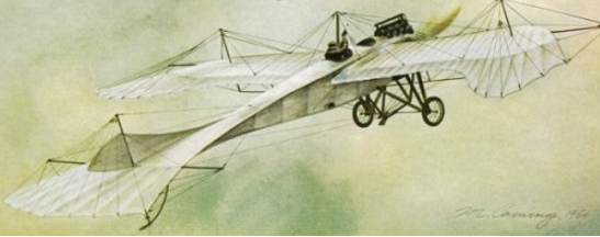
The origins of all optical systems, superimposing an additional image on the real world, are air sights. It was after the First World War, the aircraft began to be built taking into account aerodynamics, began to be equipped with powerful engines, fly quickly and high, and generally ceased to fall into a tailspin with every attempt to perform a maneuver.
As you know, the bullet fired from the machine gun is affected by gravity and the braking force of the air (which is not taken into account in this case). But if, at the time of the shot, maneuvering, and even spinning around its axis, then only the most experienced pilots could determine which direction the line would deviate.
To display the same hit point (PIP - Predicted impact point (WikiEn)or the “Forecast-track” indicator) in the early 40s, a completely mechanical system was developed that worked according to the following principle:
Seeing a target, the pilot grabbed it in a ring called a long-range, because it made it possible to enter the distance to the target in the “on-board system”. The algorithm of work was as follows - by pressing an additional pedal (with a knee), the pilot caused an extension of the ring, which then had to be reduced to the size of the enemy’s aircraft, slightly releasing the pedal. As the pilot approached, the pilot also increased the ring, gradually reducing the pressure on the pedal.
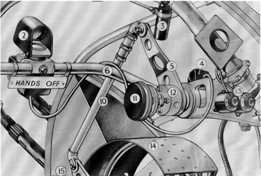
With the position in space it was easier - in the mid-30s, gyroscopes were invented, thus the on-board system mechanically transmitted information to a movable lighting system. The diagram is shown in the following figure.

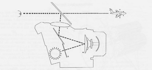
Since the error of the gyro was small, and the error of the distance was not significant (at medium ranges) - the use of such systems gave an advantage to pilots who did not have much experience.
The first to invent such a device belongs to France, but in Germany it was brought to a workable version. It can also be noted that the Germans used complex optical bomb sights.
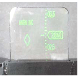
The first electronic device that used the cathode ray tube as an indicator on the windshield (ILI - Head up display (WikiEn) , was created in the USSR 5-6 years earlier than the United States. It was mounted on the MIG-15P bis interceptor. It depicted, besides the sight, also enemy aircraft position (received from radar).
The first domestic full-featured ILS were in the cockpits of MIG-27K aircraft, which were mass-produced in 1976-1982. The indicators on the windshield now displayed all the flight information (speed, altitude, horizon), and also transmitted the image from the thermal imagers (FLIR - forward looking IR - “IR camera looking forward”).
At that time, the ILS was an excellent assistant in civil aviation. Special coatings made it possible to increase the contrast of the image, reducing the transmittance of the screen at the wavelength of the image display. Thus, the image became more readable in bright light.
In 1953, the first successful AIM-9 Sidewinder thermal homing missile (Wiki) was invented . The ideal weapon, built on the principle of "shot and forgot", it allowed you to capture the target in the range of angles of ± 45 °, but the launch was usually carried out only on airplanes flying straight ahead.

Image of a homing head.
(PS we have one of these missiles at the department, it can capture the thermal radiation of an incandescent lamp or a lighter and turn behind it) The
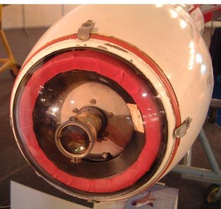
field of view of the head without an additional turn is ~ 10 ° - so you need to turn it towards the target very accurately (the joystick will not work )
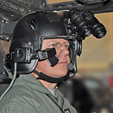
In 1974-78, systems were developed for the F-14 and F-15 aircraft that allow the pilot to rotate the seeker to the target by moving his head and combining a small mark. The mark was projected onto a small glass located in front of the eye. This was the first helmet sight.
It is worth noting that the American system was unreliable and inaccurate, so it was practically not used. Therefore, created in 1985, the Soviet system "SURAH" can rightfully be called the first mass helmet-mounted sight. The sura was installed on the MIG-25 and SU-27 aircraft and worked for the Vympel R-73 missile. The missile allows you to capture the target at a distance of 25-30 km.
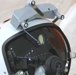
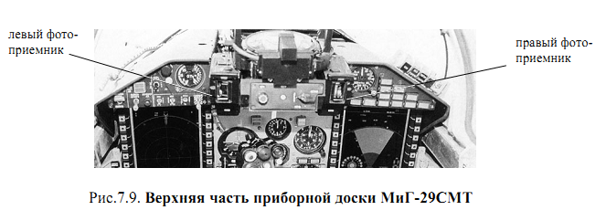
Small glass - screen, glowing lamps - positioning system
The pilot turned his head towards the enemy’s aircraft and grabbed the silhouette in the ring, which is depicted on a glass. 2 incandescent lamps located on the helmet, 2 photodetectors on the dashboard made it possible to determine the position of the gaze. (It was also possible to use electromagnetic systems, but optical accuracy was sufficient, and the presence of additional radio emitters in the cabin would interfere with the main instruments).
Almost immediately after guidance, the pilot heard a beep in the headphone and could launch.

By the way, a homing missile did not necessarily explode when hit by a target. Usually it exploded at a small distance (500 meters?) And covered a small area with steel balls. (in the form of a cone). Since the rocket speed is almost 5 max, the balls were piercing all possible armor.
On such a breakdown note, I want to go to the second part - the design .
First, please decide on the notation. The most important element that combines images is called combiner (in my diploma I just wrote - combiner) - is responsible for adding a virtual image. Usually this is a mirror with a coating that reflects the radiation wavelength of the display well, but a cube version is possible, as in google glass.
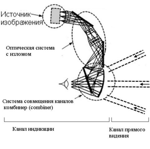
The simplest scheme, characterized by small angles and large dimensions.
According to this scheme, Google Glass and many other virtual reality glasses, professional and entertainment sectors are built.
But there is another possibility to introduce an additional image. In this case, the dimensions will be reduced and unique properties will be added.
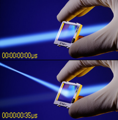
It all starts with creating a diffraction grating in the central layer of Dichromated Gelatin (DCG). This grating refracts radiation (which should be monochromatic) and deflects the beam toward the eye. The radiation coming from the real world has a weak effect on radiation, since this radiation consists of the entire spectrum of wavelengths.
Operating principle.
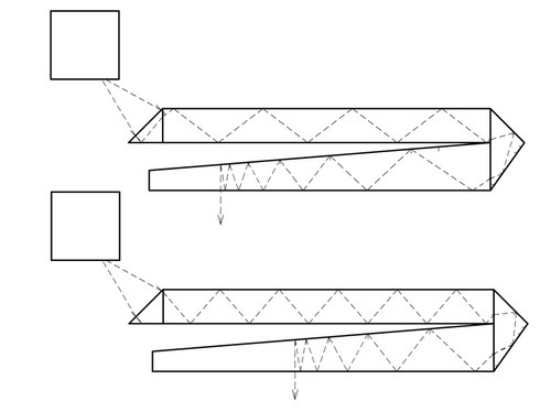
After the LCD monitor, the radiation is converted into a quasi-parallel beam and enters the plate at an angle of total internal reflection. Due to the diffraction grating located inside the plate, the beams are deflected and violate the condition of total internal reflection; in this way, a wide parallel beam hits the eye and creates the idea that the image is at infinity.

Violation of air defense due to the refraction of a part of the beam by DOE.
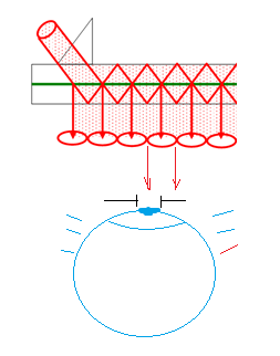
The formation of a complete inextricable output beam due to a complex diffraction grating.
It is worth noting that the user does not need to accurately establish the helmet-mounted sight, when the eye is shifted, it begins to see the neighboring beam. Perhaps there is an eye tracking system or the eye / brain is able to “glue” two halves of the image into one - anyway, it is easier for the user to use such a lightweight display.
BAE has 25 years of experience creating DCG-based windshield indicators for EFA (eurofighter), F-22, F16 fighters. Now these devices are also delivered to civilian aircraft.
In a nutshell, Bragg diffraction — under the influence of an acoustic wave caused by a glued piezoelectric vibration source on one side and a copper plate reflecting vibrations on the other — produces a standing wave, which can be considered as a diffraction grating, since the refractive index in the “nodes” and “antinodes” are different .
Under certain conditions, it is possible to single out a beam that can be effectively controlled.
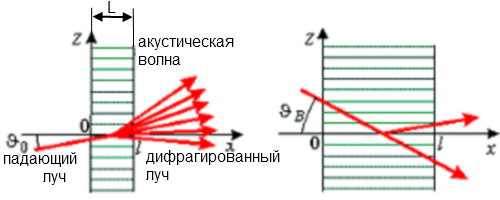
Diffraction Principle
An acoustic wave can be created, either using "mechanics" or directly, by means of an electric voltage applied to the plate. For this, special transparent film electrodes are used.
By the way, self-darkening windows are built according to a similar scheme.
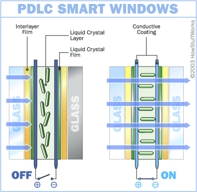
Usually in the absence of voltage the glass is frosted.
Now imagine that this is not just a Paratellurite crystal (the material that most rejects rays at the same voltage), but also inside the diffraction grating. By the way, there is a specific lattice for each wavelength, so for a full-color image, 5 lattices are used, which are switched on in turn.
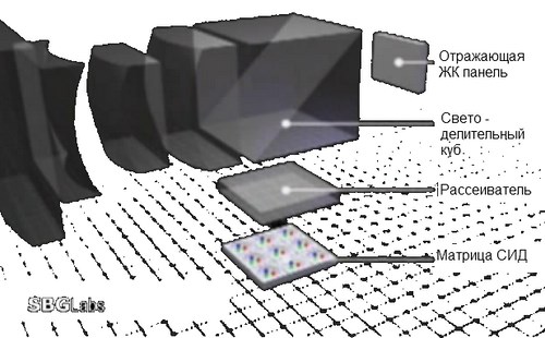
SBG Labs Inc (Switchable Bragg Grating - Switchable Bragg Grids) is located in Silicon Valley, California. First I created such plates that can simultaneously focus and deflect the beam.
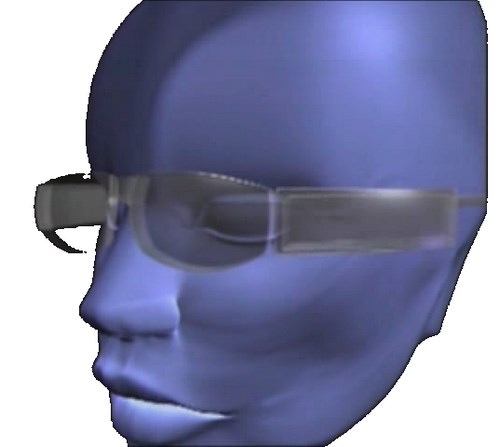
Later, virtual reality glasses were created - 40 degrees field of view, 3-color - only this is a prototype and did not go on sale, although it was developed in 1999.
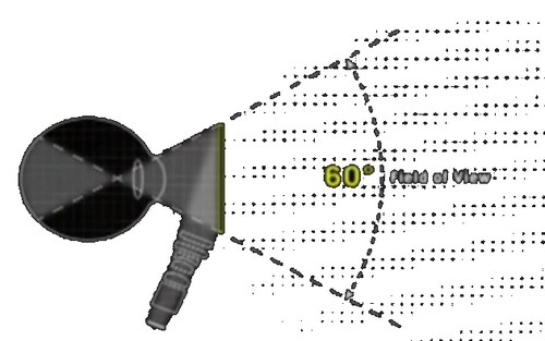
Now new glasses are under development - a resolution of 1080p, 60 degrees field of view. Functional video
:
youtu.be/XkmqKeGn4yo
Apple has registered a patent for the creation of virtual reality glasses according to the scheme of a laser TV .

It is worth noting one advantage of such a scheme.
A laser system does not need a collimator. Therefore, it is difficult for a person wearing Google glass to project an “virtually” image at a distance with this eye to look at very distant or close objects, the display image for him will immediately become blurry and the eye will try to refocus.
In "glasses from Apple", just like a laser TV is capable of projecting a clear image on a screen spaced at any distance, the laser beam will come to the retina in its original "thin" form. It is clear that if 3 lasers can be placed behind the ear, then installing a 2-coordinate scanning system (on MEMS mirrors) on the bridge of the nose is the destiny of the distant future.
After discussing such giants of the global industry, it will be honest to move on to my project and consider my development.

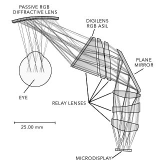
Schematic illustration of my helmet-mounted display, its photo and optical layout in Zemax. (The prism is very distorted, because the program shows the course of the rays and the location of the surfaces).
My device is exactly a copy of the helmet-mounted display, used for 20 years in the Apache helicopter. (exactly, like my diploma is a copy of the lecture materials of one southern institute (see the list of references )
In my device, the radiation source is CRT, as the most humane radiation source - when landing a helicopter, the weight of the “crest” slightly breaks the pilot’s neck, and the fallen off high-voltage cable humanely finishes it.
Thank you for being able to readthis to the end.
About me: 7 years ago when I entered the MSTU. N.E. Bauman, I chose optics as my specialty, namely the calculation of optical systems (although I, of course, did not immediately understand this). Then, my eyes were presented with optical computers and photons carrying information at the speed of light. As time went on, courses were replaced, the record from "udov" was less and less wanted to be opened, and the electrons in ordinary computers also moved at the speed of light, apparently contrary to my dreams.
My diploma topic was “Helmet Target Designation System”. Or I just said "virtual reality helmet."
The topic of the diploma surprisingly coincided with the current round of progress, and in order not to completely lose my qualifications (the diploma was successfully completed 8 months ago), I decided to write a short report describing the main points of my diploma in a popular language.
The May holidays were fruitful - I sat down and tried to rid the text of the diploma from official academic dryness and specific terms, or rather I simply rewrote it in its entirety.
Update 1. One curious fact is that an American pilot who constantly used the monocular head-mounted display found that he could move his eyes like a rabbit, i.e. literally read 2 books at a time. Although in my opinion this is an evolutionary step towards progress. Source1 Source2

Update 2. The issue with a proximity fuse requires more data and confirmation. But 500 meters seems plausible to me because even such a distance fly for 0.5 seconds at a speed of 4 Mach (* ~ 300 m / s). This information is from Professor Baumanka Odinokova S.B. at the lecture.
Update 3. Proximity fuze on non-nuclear antiaircraft missiles is activated at distances up to 100 meters. Forum Thank you, fighterjet The
core warhead of the AIM-9C Sidewinder rocket has the following parameters: 900 m / s expansion speed, 5.1 m radius of damage , 144 rods (Source)
Air sights
The origins of all optical systems, superimposing an additional image on the real world, are air sights. It was after the First World War, the aircraft began to be built taking into account aerodynamics, began to be equipped with powerful engines, fly quickly and high, and generally ceased to fall into a tailspin with every attempt to perform a maneuver.
As you know, the bullet fired from the machine gun is affected by gravity and the braking force of the air (which is not taken into account in this case). But if, at the time of the shot, maneuvering, and even spinning around its axis, then only the most experienced pilots could determine which direction the line would deviate.
To display the same hit point (PIP - Predicted impact point (WikiEn)or the “Forecast-track” indicator) in the early 40s, a completely mechanical system was developed that worked according to the following principle:
Seeing a target, the pilot grabbed it in a ring called a long-range, because it made it possible to enter the distance to the target in the “on-board system”. The algorithm of work was as follows - by pressing an additional pedal (with a knee), the pilot caused an extension of the ring, which then had to be reduced to the size of the enemy’s aircraft, slightly releasing the pedal. As the pilot approached, the pilot also increased the ring, gradually reducing the pressure on the pedal.
With the position in space it was easier - in the mid-30s, gyroscopes were invented, thus the on-board system mechanically transmitted information to a movable lighting system. The diagram is shown in the following figure.
Since the error of the gyro was small, and the error of the distance was not significant (at medium ranges) - the use of such systems gave an advantage to pilots who did not have much experience.
The first to invent such a device belongs to France, but in Germany it was brought to a workable version. It can also be noted that the Germans used complex optical bomb sights.
The first electronic device that used the cathode ray tube as an indicator on the windshield (ILI - Head up display (WikiEn) , was created in the USSR 5-6 years earlier than the United States. It was mounted on the MIG-15P bis interceptor. It depicted, besides the sight, also enemy aircraft position (received from radar).
The first domestic full-featured ILS were in the cockpits of MIG-27K aircraft, which were mass-produced in 1976-1982. The indicators on the windshield now displayed all the flight information (speed, altitude, horizon), and also transmitted the image from the thermal imagers (FLIR - forward looking IR - “IR camera looking forward”).
At that time, the ILS was an excellent assistant in civil aviation. Special coatings made it possible to increase the contrast of the image, reducing the transmittance of the screen at the wavelength of the image display. Thus, the image became more readable in bright light.
But who needed to put the pilot on this system?
In 1953, the first successful AIM-9 Sidewinder thermal homing missile (Wiki) was invented . The ideal weapon, built on the principle of "shot and forgot", it allowed you to capture the target in the range of angles of ± 45 °, but the launch was usually carried out only on airplanes flying straight ahead.
Image of a homing head.
(PS we have one of these missiles at the department, it can capture the thermal radiation of an incandescent lamp or a lighter and turn behind it) The
field of view of the head without an additional turn is ~ 10 ° - so you need to turn it towards the target very accurately (the joystick will not work )
In 1974-78, systems were developed for the F-14 and F-15 aircraft that allow the pilot to rotate the seeker to the target by moving his head and combining a small mark. The mark was projected onto a small glass located in front of the eye. This was the first helmet sight.
It is worth noting that the American system was unreliable and inaccurate, so it was practically not used. Therefore, created in 1985, the Soviet system "SURAH" can rightfully be called the first mass helmet-mounted sight. The sura was installed on the MIG-25 and SU-27 aircraft and worked for the Vympel R-73 missile. The missile allows you to capture the target at a distance of 25-30 km.
Small glass - screen, glowing lamps - positioning system
The algorithm of work was as follows:
The pilot turned his head towards the enemy’s aircraft and grabbed the silhouette in the ring, which is depicted on a glass. 2 incandescent lamps located on the helmet, 2 photodetectors on the dashboard made it possible to determine the position of the gaze. (It was also possible to use electromagnetic systems, but optical accuracy was sufficient, and the presence of additional radio emitters in the cabin would interfere with the main instruments).
Almost immediately after guidance, the pilot heard a beep in the headphone and could launch.
By the way, a homing missile did not necessarily explode when hit by a target. Usually it exploded at a small distance (500 meters?) And covered a small area with steel balls. (in the form of a cone). Since the rocket speed is almost 5 max, the balls were piercing all possible armor.
On such a breakdown note, I want to go to the second part - the design .
First, please decide on the notation. The most important element that combines images is called combiner (in my diploma I just wrote - combiner) - is responsible for adding a virtual image. Usually this is a mirror with a coating that reflects the radiation wavelength of the display well, but a cube version is possible, as in google glass.
The simplest scheme, characterized by small angles and large dimensions.
According to this scheme, Google Glass and many other virtual reality glasses, professional and entertainment sectors are built.
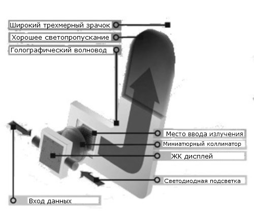
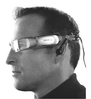
But there is another possibility to introduce an additional image. In this case, the dimensions will be reduced and unique properties will be added.
Q-sight from BAE systems.
It all starts with creating a diffraction grating in the central layer of Dichromated Gelatin (DCG). This grating refracts radiation (which should be monochromatic) and deflects the beam toward the eye. The radiation coming from the real world has a weak effect on radiation, since this radiation consists of the entire spectrum of wavelengths.
Operating principle.
After the LCD monitor, the radiation is converted into a quasi-parallel beam and enters the plate at an angle of total internal reflection. Due to the diffraction grating located inside the plate, the beams are deflected and violate the condition of total internal reflection; in this way, a wide parallel beam hits the eye and creates the idea that the image is at infinity.
Violation of air defense due to the refraction of a part of the beam by DOE.
The formation of a complete inextricable output beam due to a complex diffraction grating.
It is worth noting that the user does not need to accurately establish the helmet-mounted sight, when the eye is shifted, it begins to see the neighboring beam. Perhaps there is an eye tracking system or the eye / brain is able to “glue” two halves of the image into one - anyway, it is easier for the user to use such a lightweight display.
BAE has 25 years of experience creating DCG-based windshield indicators for EFA (eurofighter), F-22, F16 fighters. Now these devices are also delivered to civilian aircraft.
2 "complex" version of the combination system. Bragg diffraction
In a nutshell, Bragg diffraction — under the influence of an acoustic wave caused by a glued piezoelectric vibration source on one side and a copper plate reflecting vibrations on the other — produces a standing wave, which can be considered as a diffraction grating, since the refractive index in the “nodes” and “antinodes” are different .
Under certain conditions, it is possible to single out a beam that can be effectively controlled.
Diffraction Principle
An acoustic wave can be created, either using "mechanics" or directly, by means of an electric voltage applied to the plate. For this, special transparent film electrodes are used.
By the way, self-darkening windows are built according to a similar scheme.
Usually in the absence of voltage the glass is frosted.
Now imagine that this is not just a Paratellurite crystal (the material that most rejects rays at the same voltage), but also inside the diffraction grating. By the way, there is a specific lattice for each wavelength, so for a full-color image, 5 lattices are used, which are switched on in turn.
SBG Labs Inc (Switchable Bragg Grating - Switchable Bragg Grids) is located in Silicon Valley, California. First I created such plates that can simultaneously focus and deflect the beam.
Later, virtual reality glasses were created - 40 degrees field of view, 3-color - only this is a prototype and did not go on sale, although it was developed in 1999.
Now new glasses are under development - a resolution of 1080p, 60 degrees field of view. Functional video
:
youtu.be/XkmqKeGn4yo
Apple Glasses
Apple has registered a patent for the creation of virtual reality glasses according to the scheme of a laser TV .
It is worth noting one advantage of such a scheme.
A laser system does not need a collimator. Therefore, it is difficult for a person wearing Google glass to project an “virtually” image at a distance with this eye to look at very distant or close objects, the display image for him will immediately become blurry and the eye will try to refocus.
In "glasses from Apple", just like a laser TV is capable of projecting a clear image on a screen spaced at any distance, the laser beam will come to the retina in its original "thin" form. It is clear that if 3 lasers can be placed behind the ear, then installing a 2-coordinate scanning system (on MEMS mirrors) on the bridge of the nose is the destiny of the distant future.
After discussing such giants of the global industry, it will be honest to move on to my project and consider my development.
Schematic illustration of my helmet-mounted display, its photo and optical layout in Zemax. (The prism is very distorted, because the program shows the course of the rays and the location of the surfaces).
My device is exactly a copy of the helmet-mounted display, used for 20 years in the Apache helicopter. (exactly, like my diploma is a copy of the lecture materials of one southern institute (see the list of references )
In my device, the radiation source is CRT, as the most humane radiation source - when landing a helicopter, the weight of the “crest” slightly breaks the pilot’s neck, and the fallen off high-voltage cable humanely finishes it.
Thank you for being able to read
About me: 7 years ago when I entered the MSTU. N.E. Bauman, I chose optics as my specialty, namely the calculation of optical systems (although I, of course, did not immediately understand this). Then, my eyes were presented with optical computers and photons carrying information at the speed of light. As time went on, courses were replaced, the record from "udov" was less and less wanted to be opened, and the electrons in ordinary computers also moved at the speed of light, apparently contrary to my dreams.
My diploma topic was “Helmet Target Designation System”. Or I just said "virtual reality helmet."
The topic of the diploma surprisingly coincided with the current round of progress, and in order not to completely lose my qualifications (the diploma was successfully completed 8 months ago), I decided to write a short report describing the main points of my diploma in a popular language.
The May holidays were fruitful - I sat down and tried to rid the text of the diploma from official academic dryness and specific terms, or rather I simply rewrote it in its entirety.
Update 1. One curious fact is that an American pilot who constantly used the monocular head-mounted display found that he could move his eyes like a rabbit, i.e. literally read 2 books at a time. Although in my opinion this is an evolutionary step towards progress. Source1 Source2
Update 2. The issue with a proximity fuse requires more data and confirmation. But 500 meters seems plausible to me because even such a distance fly for 0.5 seconds at a speed of 4 Mach (* ~ 300 m / s). This information is from Professor Baumanka Odinokova S.B. at the lecture.
Update 3. Proximity fuze on non-nuclear antiaircraft missiles is activated at distances up to 100 meters. Forum Thank you, fighterjet The
core warhead of the AIM-9C Sidewinder rocket has the following parameters: 900 m / s expansion speed, 5.1 m radius of damage , 144 rods (Source)
List of references:
Books that will be useful to those interested in aviation and in particular helmet displays:
1. On-board information systems: Lecture course: A. Kucheryavy 2004 year. (The only material in Russian. Despite the late publication period - relevant)
2. Wiley - Military Avionics Systems (2006)
3. Advanced Avionics Handbook (for pilots, “how to use the plane”)
4. British Aircraft Armament (read from here, about the “mechanical sight.” - last Appendix B)

Original photo
Honestly, I’m unsure of some of the small details, so I’ll be happy for any comments.
1. On-board information systems: Lecture course: A. Kucheryavy 2004 year. (The only material in Russian. Despite the late publication period - relevant)
2. Wiley - Military Avionics Systems (2006)
3. Advanced Avionics Handbook (for pilots, “how to use the plane”)
4. British Aircraft Armament (read from here, about the “mechanical sight.” - last Appendix B)
Original photo
Honestly, I’m unsure of some of the small details, so I’ll be happy for any comments.