Writing Linux kernel module: IRQ-enabled GPIO
- Tutorial
Habr, hello!
This article is devoted to the development of GPIO (General-Purpose Input / Output) module of the Linux kernel. As in the previous article, we will implement the basic structure of the GPIO driver with interrupt support (IRQ: Interrupt Request).
The inputs are similar to the previous article: the GPIO unit for the FPGA “wired up” developed by the GPIO and launched by Linux version 3.18.19.
In order to develop a GPIO driver, we need to perform the following steps:
Examples of GPIO drivers can be found here .
For a start, let's get acquainted with the principle of GPIO driver interaction through the user console.
Using a small bash script, create the controls of each GPIO in / sysfs. To do this, in the command line you need to write the following script:
Next, let's see what features / sysfs provides for configuring each GPIO:
At the moment we are interested in the following fields:
After a quick acquaintance with the driver interaction interface via sysfs, you can see how the driver handles user commands. In the Linux kernel there is a gpio_chip structure that describes the functionality of the gpio controller. It contains the following fields:
To describe the IRQ configuration in Linux, there is an irq_chip structure that contains the following fields:
Now you can add the driver to the assembly and describe the hardware by performing the standard actions already. First create the source file:
After we add the driver configuration to drivers / gpio / Kconfig :
Add the driver to the assembly in drivers / gpio / Makefile :
And finally, add a description of a GPIO block to devicetree (* .dts):
More information about devicetree can be found here .
Let's move on to the most interesting part for us!
We will start developing the driver by connecting the necessary header files and describing the complete skeleton of the driver without IRQ support. Further we will consistently fill each function with a code and accompany it with necessary explanations.
As can be seen from the implementation, the driver skeleton looks quite simple and contains not so many necessary functions and structures.
In order to describe the future driver we will need the following elements:
Further, in order to load / extract the driver to / from Linux, you need to implement the .probe and .remove methods specified in the skel_gpio_driver structure .
The skel_gpio_remove function simply removes the registered GPIO driver from the kernel, so consider the main points in skel_gpio_probe:
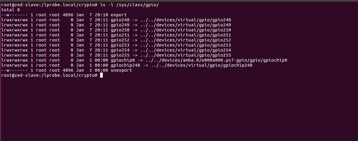
Until now, it has not been described why such magic numbers as 248 ... 255 are used. The record skel_gc-> gchip.base = -1; asks the kernel to dynamically allocate the numbers used by the GPIO. To find out these numbers at the end of the driver added output:
Of course, Linux provides the ability to set numbers manually, but let's look at the comment in the source code :
Consider the functional part of the driver, namely, we implement the following methods:
.direction_output , .direction_input , .get and .set . Next will be shown a hardware-dependent code, which in most cases will be different.
The skel_gpio_direction_input method performs the following actions:
The skel_gpio_direction_output method performs actions similar to skel_gpio_direction_inut, except that it is called with the following commands:
value is a value that determines the signal level on the output line.
The skel_gpio_set method performs the following actions:
The skel_gpio_get method reads the value of a signal on a line by reading the SKEL_GPIO_RD_DATA register.
After we have described all the necessary methods and structures, you can put everything together and look at the final version.
The implemented driver contains the necessary functionality for managing GPIO, but at the moment there is no support for working with interrupts in the driver, so you can proceed to the next step.
Adding an IRQ to a GPIO driver can be divided into three steps:
Initially, we will describe the required set of operations:
Therefore, the driver can allow (skel_gpio_irq_unmask) / disable (skel_gpio_irq_mask) interrupts and specify the type of event for which it will be generated (skel_gpio_irq_set_type).
Next, we describe the only method that is responsible for matching the virtual irq number with the hardware one.
Then we will tell the kernel that the loadable driver supports IRQ. To do this, add the following code to the probe function:
In the above code occurs:
We proceed to implement some of the methods described above.
skel_gpio_to_irq - creates a mapping between hardware and virtual interrupts. If this mapping has already been created, then returns the number of the created virtual interrupt.
skel_irq_handler - interrupt handler that:
That's all, in this article we learned how the GPIO driver interacts with the sysfs virtual file system, implemented the basic structure of the GPIO driver, and also looked at the methods required to support IRQ.
The article does not show the implementation of the skel_gpio_irq_unmask, skel_gpio_irq_mask and skel_gpio_irq_set_type methods for two reasons. First, these methods are simple to implement. Secondly, hardware-dependent. They are responsible for enabling or disabling interrupts for certain events that the GPIO controller supports.
Please, if you have found any errors / inaccuracies, or you have something to add - write to the PM or in the comments.
Thank you for your attention!
This article is devoted to the development of GPIO (General-Purpose Input / Output) module of the Linux kernel. As in the previous article, we will implement the basic structure of the GPIO driver with interrupt support (IRQ: Interrupt Request).
The inputs are similar to the previous article: the GPIO unit for the FPGA “wired up” developed by the GPIO and launched by Linux version 3.18.19.
In order to develop a GPIO driver, we need to perform the following steps:
- Understand how GPIO drivers interact with the user space interface;
- Add the kernel module to the assembly and describe the hardware in the device tree;
- Implement the basic driver skeleton, as well as its entry and extraction points;
- Implement the functional part of the GPIO driver;
- Add IRQ support to the driver implementation.
Examples of GPIO drivers can be found here .
Step one
For a start, let's get acquainted with the principle of GPIO driver interaction through the user console.
Using a small bash script, create the controls of each GPIO in / sysfs. To do this, in the command line you need to write the following script:
for i in {248..255}; doecho$i > /sys/class/gpio/export; doneNext, let's see what features / sysfs provides for configuring each GPIO:
root@zed-slave:/sys/class/gpio# ls -lgpio248/
total 0
-rw-r--r-- 1 rootroot 4096 Jan  7 20:50 active_low
-rw-r--r-- 1 root root 4096 Jan  720:50 direction
-rw-r--r-- 1 root root 4096 Jan  720:50 edge
drwxr-xr-x 2 root root    0 Jan  720:50 power
lrwxrwxrwx 1 root root    0 Jan  720:50 subsystem -> ../../../../class/gpio
-rw-r--r-- 1 rootroot 4096 Jan  7 20:10 uevent
-rw-r--r-- 1 root root 4096 Jan  720:50 value
At the moment we are interested in the following fields:
- direction - sets the direction of the line. It can be “in” or “out”;
- value - allows you to set a high or low signal on the line (if direction is set to “out”), otherwise (direction is set to “in”) allows you to read the state of the line;
- edge - allows you to configure an event for which an interrupt occurs. It can take the following values: “none”, “rising”, “falling” or “both”.
After a quick acquaintance with the driver interaction interface via sysfs, you can see how the driver handles user commands. In the Linux kernel there is a gpio_chip structure that describes the functionality of the gpio controller. It contains the following fields:
- direction_input : sets the line to enter. Called with the following entry: echo "in"> / sys / class / gpio / gpio248 / direction;
- direction_output : sets the line to exit. Called with the following entry: echo "out"> / sys / class / gpio / gpio248 / direction;
- get : reads the value set on the line. Called with the following entry: cat / sys / class / gpio / gpio248 / value;
- set : sets the value on the line. Called with the following entry: echo 1/0> / sys / class / gpio / gpio248 / value;
To describe the IRQ configuration in Linux, there is an irq_chip structure that contains the following fields:
- irq_set_type : sets the type of event by which the interrupt will occur. Called with the following entry: echo> "rising" / "falling" / "both"> / sys / class / gpio / gpio248 / edge;
- irq_mask : disables interrupts. Called with the following entry: echo "none"> / sys / class / gpio / gpio248 / edge;
- irq_unmask : enables an interrupt on an event that has been set to irq_set_type. Called immediately after running irq_set_type.
Step two
Now you can add the driver to the assembly and describe the hardware by performing the standard actions already. First create the source file:
cd drivers/gpio/
vim gpio-skel.c
:wq
After we add the driver configuration to drivers / gpio / Kconfig :
config GPIO_SKEL
	tristate "SKEL GPIO"help
	  Say yes here to support SKEL GPIO.
Add the driver to the assembly in drivers / gpio / Makefile :
obj-$(CONFIG_GPIO_SKEL) += gpio-skel.o
And finally, add a description of a GPIO block to devicetree (* .dts):
gpio: gpio@f8f01d00 {
	compatible = "skel-gpio";
	rcm,ngpio = <8>;
	rcm,interrupt-type = <IRQ_TYPE_EDGE_RISING>;
	clocks = <&clkc 42>;
	gpio-controller ;
 	interrupt-parent = <&ps7_scugic_0>;
 	interrupts = <0 29 4>;
	reg = <0x43c00000 0x100>;
 } ;
More information about devicetree can be found here .
Step Three
Let's move on to the most interesting part for us!
We will start developing the driver by connecting the necessary header files and describing the complete skeleton of the driver without IRQ support. Further we will consistently fill each function with a code and accompany it with necessary explanations.
GPIO driver skeleton
/* gpio-skel.c: GPIO driver
 *
 * Name Surname <email>
 *
 * This file is licensed under the terms of the GNU General Public License
 * version 2. This program is licensed "as is" without any warranty of any
 * kind, whether express or implied.
 */#include<linux/of.h>#include<linux/irq.h>#include<linux/io.h>#include<linux/irqdomain.h>#include<linux/bitops.h>#include<linux/irqchip/chained_irq.h>#include<linux/interrupt.h>#include<linux/slab.h>#include<linux/module.h>#include<linux/kernel.h>#include<linux/gpio/driver.h>#include<linux/platform_device.h>#define SKEL_GPIO_VER			0x04#define SKEL_GPIO_PAD_DIR		0x08#define SKEL_GPIO_WR_DATA		0x0C#define SKEL_GPIO_RD_DATA		0x10#define SKEL_GPIO_WR_DATA1		0x1C#define SKEL_GPIO_WR_DATA0		0x20#define SKEL_GPIO_SRC			0x24#define SKEL_GPIO_MAX_NGPIO	8#define GPIO_OFFSET	4structskel_gpio_chip {structgpio_chipgchip;spinlock_t lock;
	void __iomem *regs;
	u32 type;
};
staticinlinevoidgpio_write(uint32_t value, void *base, uint32_t addr){
	writel(value, base + addr);
#if defined DEBUG
	dev_dbg(rdev->dev, "iowrite32(0x%x, base + 0x%x);\n", value, addr);
#endif
}
staticinline uint32_t gpio_read(void *base, uint32_t addr){
	uint32_t reg =  readl(base + addr);
#if defined DEBUG
	dev_dbg(rdev->dev, "/* ioread32(base + 0x%x) == 0x%x */\n", addr, reg);
#endifreturn reg;
}
staticinline struct skel_gpio_chip *to_skel_gpio(struct gpio_chip *chip){
}
/*
 * echo "in" > /sys/class/gpio/gpioN/direction
 */staticintskel_gpio_direction_input(struct gpio_chip *chip, unsigned offset){
}
/*
 * echo "out" > /sys/class/gpio/gpioN/direction
 */staticintskel_gpio_direction_output(struct gpio_chip *chip,
			unsigned offset, int value){
}
staticintskel_gpio_get(struct gpio_chip *chip, unsigned offset){
}
staticvoidskel_gpio_set(struct gpio_chip *chip,
			unsigned offset, int value){
}
staticintskel_gpio_probe(struct platform_device *pdev){
}
staticintskel_gpio_remove(struct platform_device *pdev){
}
staticconststructof_device_idskel_gpio_of_match[] = {
	{ .compatible = "skel-gpio" },
	{ },
};
MODULE_DEVICE_TABLE(of, skel_gpio_of_match);
staticstructplatform_driverskel_gpio_driver = {
	.probe = skel_gpio_probe,
	.remove = skel_gpio_remove,
	.driver = {
		.name = "skel-gpio",
		.of_match_table = of_match_ptr(skel_gpio_of_match),
	},
};
module_platform_driver(skel_gpio_driver);
MODULE_DESCRIPTION("GPIO driver");
MODULE_AUTHOR("Name Surname");
MODULE_LICENSE("GPL");
As can be seen from the implementation, the driver skeleton looks quite simple and contains not so many necessary functions and structures.
In order to describe the future driver we will need the following elements:
- platform_driver skel_gpio_driver - describes the entry point skel_gpio_probe when loading the driver and skel_gpio_remove when it is removed from the kernel;
- struct of_device_id skel_gpio_of_match - contains a table that describes the hardware part of the GPIO block;
- struct skel_gpio_chip - contains the necessary fields to control the GPIO driver block.
Further, in order to load / extract the driver to / from Linux, you need to implement the .probe and .remove methods specified in the skel_gpio_driver structure .
Implementation skel_gpio_probe
staticintskel_gpio_probe(struct platform_device *pdev){
	structdevice_node *node = pdev->dev.of_node;structskel_gpio_chip *skel_gc;structresource *res;int ngpio, ret;
	skel_gc = devm_kzalloc(&pdev->dev, sizeof(*skel_gc), GFP_KERNEL);
	if (!skel_gc)
		return -ENOMEM;
	spin_lock_init(&skel_gc->lock);
	res = platform_get_resource(pdev, IORESOURCE_MEM, 0);
	if (!res) {
		dev_err(&pdev->dev, "Failed to get MMIO resource for GPIO.\n");
		return -EINVAL;
	}
	skel_gc->regs = devm_ioremap_resource(&pdev->dev, res);
	if (!skel_gc->regs)
		gotofree;
	if (!of_property_read_u32(node, "skel,ngpio", &ngpio))
		skel_gc->gchip.ngpio = ngpio;
	else
		skel_gc->gchip.ngpio = SKEL_GPIO_MAX_NGPIO;
	if (skel_gc->gchip.ngpio > SKEL_GPIO_MAX_NGPIO) {
		dev_warn(&pdev->dev, "Number of gpio is greater than MAX!\n");
		skel_gc->gchip.ngpio = SKEL_GPIO_MAX_NGPIO;
	}
	skel_gc->gchip.direction_input = skel_gpio_direction_input;
	skel_gc->gchip.direction_output = skel_gpio_direction_output;
	skel_gc->gchip.get = skel_gpio_get;
	skel_gc->gchip.set = skel_gpio_set;
	skel_gc->gchip.owner = THIS_MODULE;
	skel_gc->gchip.base = -1;
	platform_set_drvdata(pdev, skel_gc);
	ret = gpiochip_add(&skel_gc->gchip);
	if (ret) {
		dev_err(&pdev->dev, "Failed adding memory mapped gpiochip\n");
		return ret;
	}
	dev_info(&pdev->dev, "SKEL GPIO probe complete: (%d .. %d)\n",
				skel_gc->gchip.base,
				skel_gc->gchip.base + skel_gc->gchip.ngpio);
	return0;
}
Implementation skel_gpio_remove
staticintskel_gpio_remove(struct platform_device *pdev){
	structskel_gpio_chip *skel_gc = platform_get_drvdata(pdev);
	gpiochip_remove(&skel_gc->gchip);
	return0;
}
The skel_gpio_remove function simply removes the registered GPIO driver from the kernel, so consider the main points in skel_gpio_probe:
- devm_kzalloc - allocates memory for the skel_gpio_chip structure;
- platform_get_resource - reads the address of the beginning of the register GPIO map from devicetree;
- devm_ioremap_resource - performs mapping of a physical address on a virtual one;
- of_property_read_u32 - reads the number of available GPIO from devicetree;
- skel_gc-> gchip. * - fills the fields of the structure necessary for the work;
- gpiochip_add - adds a GPIO controller to the driver;
Until now, it has not been described why such magic numbers as 248 ... 255 are used. The record skel_gc-> gchip.base = -1; asks the kernel to dynamically allocate the numbers used by the GPIO. To find out these numbers at the end of the driver added output:
dev_info(&pdev->dev, "SKEL GPIO probe complete: (%d .. %d)\n",
				skel_gc->gchip.base,
				skel_gc->gchip.base + skel_gc->gchip.ngpio);
Of course, Linux provides the ability to set numbers manually, but let's look at the comment in the source code :
@base: identifies the first GPIO number handled by this chip;
 *	or, if negative during registration, requests dynamic ID allocation.
 *	DEPRECATION: providing anything non-negative and nailing the base
 *	offset of GPIO chips is deprecated. Please pass -1 as base to
 *	let gpiolib select the chip base in all possible cases. We want to
 *	get rid of the static GPIO number space in the long run.
Step Four
Consider the functional part of the driver, namely, we implement the following methods:
.direction_output , .direction_input , .get and .set . Next will be shown a hardware-dependent code, which in most cases will be different.
Implementation skel_gpio_direction_input
/*
 * echo "in" > /sys/class/gpio/gpioN/direction
 */staticintskel_gpio_direction_input(struct gpio_chip *chip, unsigned offset){
	structskel_gpio_chip *gc = to_skel_gpio(chip);unsignedlong flag;
	u32 data_dir;
	spin_lock_irqsave(&gc->lock, flag);
	data_dir = gpio_read(gc->regs, SKEL_GPIO_PAD_DIR);
	data_dir &= ~BIT(offset);
	gpio_write(data_dir, gc->regs, SKEL_GPIO_PAD_DIR);
	spin_unlock_irqrestore(&gc->lock, flag);
	return0;
}
The skel_gpio_direction_input method performs the following actions:
- Called with the following echo command “in”> / sys / class / gpio / gpioN / direction;
- Reads the SKEL_GPIO_PAD_DIR register, which is responsible for setting the direction of the GPIO pin;
- Sets the required mask;
- Writes the resulting value back to SKEL_GPIO_PAD_DIR.
Implementation skel_gpio_direction_output
/*
 * echo "out" > /sys/class/gpio/gpioN/direction
 */staticintskel_gpio_direction_output(struct gpio_chip *chip,
			unsigned offset, int value){
	structskel_gpio_chip *gc = to_skel_gpio(chip);unsignedlong flag;
	u32 data_reg, data_dir;
	spin_lock_irqsave(&gc->lock, flag);
	data_reg = gpio_read(gc->regs, SKEL_GPIO_WR_DATA);
	if (value)
		data_reg |= BIT(offset);
	else
		data_reg &= ~BIT(offset);
	gpio_write(data_reg, gc->regs, SKEL_GPIO_WR_DATA);
	data_dir = gpio_read(gc->regs, SKEL_GPIO_PAD_DIR);
	data_dir |= BIT(offset);
	gpio_write(data_dir, gc->regs, SKEL_GPIO_PAD_DIR);
	spin_unlock_irqrestore(&gc->lock, flag);
	return0;
}
The skel_gpio_direction_output method performs actions similar to skel_gpio_direction_inut, except that it is called with the following commands:
- echo "out"> / sys / class / gpio / gpioN / direction;
- echo "high"> / sys / class / gpio / gpioN / direction, setting the value to 1;
- echo "low"> / sys / class / gpio / gpioN / direction, setting the value to 0.
value is a value that determines the signal level on the output line.
Implementation skel_gpio_set
staticvoidskel_gpio_set(struct gpio_chip *chip,
			unsigned offset, int value){
	structskel_gpio_chip *gc = to_skel_gpio(chip);unsignedlong flag;
	unsignedint data_reg;
	spin_lock_irqsave(&gc->lock, flag);
	data_reg = gpio_read(gc->regs, SKEL_GPIO_WR_DATA);
	if (value)
		data_reg |= BIT(offset);
	else
		data_reg &= ~BIT(offset);
	gpio_write(data_reg, gc->regs, SKEL_GPIO_WR_DATA);
	spin_unlock_irqrestore(&gc->lock, flag);
}
The skel_gpio_set method performs the following actions:
- Called with the following echo 1/0> / sys / class / gpio / gpioN / value;
- Reads the SKEL_GPIO_WR_DATA register, which shows the value of the current signal on the line;
- Sets or resets the required bit by offset;
- Writes the resulting value back to SKEL_GPIO_WR_DATA.
Implementation skel_gpio_get
staticintskel_gpio_get(struct gpio_chip *chip, unsigned offset){
	structskel_gpio_chip *gc = to_skel_gpio(chip);return !!(gpio_read(gc->regs, SKEL_GPIO_RD_DATA) & BIT(offset));
}
The skel_gpio_get method reads the value of a signal on a line by reading the SKEL_GPIO_RD_DATA register.
After we have described all the necessary methods and structures, you can put everything together and look at the final version.
GPIO driver implementation
/* gpio-skel.c: GPIO driver
 *
 * Name Surname <email>
 *
 * This file is licensed under the terms of the GNU General Public License
 * version 2. This program is licensed "as is" without any warranty of any
 * kind, whether express or implied.
 */#include<linux/of.h>#include<linux/irq.h>#include<linux/io.h>#include<linux/irqdomain.h>#include<linux/bitops.h>#include<linux/irqchip/chained_irq.h>#include<linux/interrupt.h>#include<linux/slab.h>#include<linux/module.h>#include<linux/kernel.h>#include<linux/gpio/driver.h>#include<linux/platform_device.h>#define SKEL_GPIO_VER			0x04#define SKEL_GPIO_PAD_DIR		0x08#define SKEL_GPIO_WR_DATA		0x0C#define SKEL_GPIO_RD_DATA		0x10#define SKEL_GPIO_WR_DATA1		0x1C#define SKEL_GPIO_WR_DATA0		0x20#define SKEL_GPIO_SRC			0x24#define SKEL_GPIO_MAX_NGPIO	8#define GPIO_OFFSET	4structskel_gpio_chip {structgpio_chipgchip;spinlock_t lock;
	void __iomem *regs;
	u32 type;
};
staticinlinevoidgpio_write(uint32_t value, void *base, uint32_t addr){
	writel(value, base + addr);
#if defined DEBUG
	dev_dbg(rdev->dev, "iowrite32(0x%x, base + 0x%x);\n", value, addr);
#endif
}
staticinline uint32_t gpio_read(void *base, uint32_t addr){
	uint32_t reg =  readl(base + addr);
#if defined DEBUG
	dev_dbg(rdev->dev, "/* ioread32(base + 0x%x) == 0x%x */\n", addr, reg);
#endifreturn reg;
}
staticinline struct skel_gpio_chip *to_skel_gpio(struct gpio_chip *chip){
	return container_of(chip, struct skel_gpio_chip, gchip);
}
/*
 * echo > "out" > /sys/class/gpio/gpioN/direction
 */staticintskel_gpio_direction_output(struct gpio_chip *chip,
			unsigned offset, int value){
	structskel_gpio_chip *gc = to_skel_gpio(chip);unsignedlong flag;
	u32 data_reg, data_dir;
	spin_lock_irqsave(&gc->lock, flag);
	data_reg = gpio_read(gc->regs, SKEL_GPIO_WR_DATA);
	if (value)
		data_reg |= BIT(offset);
	else
		data_reg &= ~BIT(offset);
	gpio_write(data_reg, gc->regs, SKEL_GPIO_WR_DATA);
	data_dir = gpio_read(gc->regs, SKEL_GPIO_PAD_DIR);
	data_dir |= BIT(offset);
	gpio_write(data_dir, gc->regs, SKEL_GPIO_PAD_DIR);
	spin_unlock_irqrestore(&gc->lock, flag);
	return0;
}
/*
 * echo > "in" > /sys/class/gpio/gpioN/direction
 */staticintskel_gpio_direction_input(struct gpio_chip *chip, unsigned offset){
	structskel_gpio_chip *gc = to_skel_gpio(chip);unsignedlong flag;
	u32 data_dir;
	spin_lock_irqsave(&gc->lock, flag);
	data_dir = gpio_read(gc->regs, SKEL_GPIO_PAD_DIR);
	data_dir &= ~BIT(offset);
	gpio_write(data_dir, gc->regs, SKEL_GPIO_PAD_DIR);
	spin_unlock_irqrestore(&gc->lock, flag);
	return0;
}
staticintskel_gpio_get(struct gpio_chip *chip, unsigned offset){
	structskel_gpio_chip *gc = to_skel_gpio(chip);return !!(gpio_read(gc->regs, SKEL_GPIO_RD_DATA) & BIT(offset));
}
staticvoidskel_gpio_set(struct gpio_chip *chip,
			unsigned offset, int value){
	structskel_gpio_chip *gc = to_skel_gpio(chip);unsignedlong flag;
	unsignedint data_reg;
	spin_lock_irqsave(&gc->lock, flag);
	data_reg = gpio_read(gc->regs, SKEL_GPIO_WR_DATA);
	if (value)
		data_reg |= BIT(offset);
	else
		data_reg &= ~BIT(offset);
	gpio_write(data_reg, gc->regs, SKEL_GPIO_WR_DATA);
	spin_unlock_irqrestore(&gc->lock, flag);
}
staticintskel_gpio_remove(struct platform_device *pdev){
	structskel_gpio_chip *skel_gc = platform_get_drvdata(pdev);
	gpiochip_remove(&skel_gc->gchip);
	return0;
}
staticintskel_gpio_probe(struct platform_device *pdev){
	structdevice_node *node = pdev->dev.of_node;structskel_gpio_chip *skel_gc;structresource *res;int ngpio, ret;
	skel_gc = devm_kzalloc(&pdev->dev, sizeof(*skel_gc), GFP_KERNEL);
	if (!skel_gc)
		return -ENOMEM;
	spin_lock_init(&skel_gc->lock);
	res = platform_get_resource(pdev, IORESOURCE_MEM, 0);
	if (!res) {
		dev_err(&pdev->dev, "Failed to get MMIO resource for GPIO.\n");
		return -EINVAL;
	}
	skel_gc->regs = devm_ioremap_resource(&pdev->dev, res);
	if (!skel_gc->regs)
		return -ENXIO;
	if (!of_property_read_u32(node, "skel,ngpio", &ngpio))
		skel_gc->gchip.ngpio = ngpio;
	else
		skel_gc->gchip.ngpio = SKEL_GPIO_MAX_NGPIO;
	if (skel_gc->gchip.ngpio > SKEL_GPIO_MAX_NGPIO) {
		dev_warn(&pdev->dev, "Number of gpio is greater than MAX!\n");
		skel_gc->gchip.ngpio = SKEL_GPIO_MAX_NGPIO;
	}
	skel_gc->gchip.direction_input = skel_gpio_direction_input;
	skel_gc->gchip.direction_output = skel_gpio_direction_output;
	skel_gc->gchip.get = skel_gpio_get;
	skel_gc->gchip.set = skel_gpio_set;
	skel_gc->gchip.owner = THIS_MODULE;
	skel_gc->gchip.base = -1;
	platform_set_drvdata(pdev, skel_gc);
	ret = gpiochip_add(&skel_gc->gchip);
	if (ret) {
		dev_err(&pdev->dev, "Failed adding memory mapped gpiochip\n");
		return ret;
	}
	dev_info(&pdev->dev, "SKEL GPIO probe complete: (%d .. %d)\n",
				skel_gc->gchip.base,
				skel_gc->gchip.base + skel_gc->gchip.ngpio);
	return0;
}
staticconststructof_device_idskel_gpio_of_match[] = {
	{ .compatible = "skel-gpio" },
	{ },
};
MODULE_DEVICE_TABLE(of, skel_gpio_of_match);
staticstructplatform_driverskel_gpio_driver = {
	.probe = skel_gpio_probe,
	.remove = skel_gpio_remove,
	.driver = {
		.name = "skel-gpio",
		.of_match_table = of_match_ptr(skel_gpio_of_match),
	},
};
module_platform_driver(skel_gpio_driver);
MODULE_DESCRIPTION("GPIO driver");
MODULE_AUTHOR("Name Surname");
MODULE_LICENSE("GPL");
The implemented driver contains the necessary functionality for managing GPIO, but at the moment there is no support for working with interrupts in the driver, so you can proceed to the next step.
Step five
Adding an IRQ to a GPIO driver can be divided into three steps:
- Description of supported methods in kernel data structures;
- Enabling IRQ support when the driver is loaded into the system;
- Implementing supported methods.
Initially, we will describe the required set of operations:
staticstructirq_chipskel_irq_chip = {
	.name = "skel-gpio",
	.irq_mask = skel_gpio_irq_mask,
	.irq_unmask = skel_gpio_irq_unmask,
	.irq_set_type = skel_gpio_irq_set_type,
};
Therefore, the driver can allow (skel_gpio_irq_unmask) / disable (skel_gpio_irq_mask) interrupts and specify the type of event for which it will be generated (skel_gpio_irq_set_type).
Next, we describe the only method that is responsible for matching the virtual irq number with the hardware one.
staticstructirq_domain_opsskel_gpio_irq_domain_ops = {
	.map = skel_gpio_irq_domain_map,
};
Then we will tell the kernel that the loadable driver supports IRQ. To do this, add the following code to the probe function:
Adding IRQ support
skel_gc->gchip.to_irq = skel_gpio_to_irq;
skel_gc->domain = irq_domain_add_linear(pdev->dev.of_node,
						rcm_gc->gchip.ngpio,
						&skel_gpio_irq_domain_ops,
						skel_gc);
if (!skel_gc->domain)
	return -ENODEV;
skel_gc->irq = platform_get_irq(pdev, 0);
if (skel_gc->irq < 0)
	gotofree;
for (i = 0; i < skel_gc->gchip.ngpio; i++) {
	int irq = rcm_gpio_to_irq(&skel_gc->gchip, i);
	irq_set_chip_and_handler(irq, &skel_irq_chip, handle_simple_irq);
#ifdef CONFIG_ARM
        set_irq_flags(irq, IRQF_VALID);
#else
        irq_set_noprobe(irq);
#endif
	}
irq_set_chained_handler(skel_gc->irq, skel_irq_handler);
irq_set_handler_data(skel_gc->irq, skel_gc);
In the above code occurs:
- Selection and initialization of the area under irq_domain;
- Read interrupt number from devicetree;
- mapping between virtual and hardware interrupts;
- Register an interrupt handler and set data to be sent to the handler;
We proceed to implement some of the methods described above.
skel_gpio_to_irq - creates a mapping between hardware and virtual interrupts. If this mapping has already been created, then returns the number of the created virtual interrupt.
Implementation skel_gpio_to_irq
staticintskel_gpio_to_irq(struct gpio_chip *chip, unsigned gpio){
	structskel_gpio_chip *rcm = to_skel_gpio(chip);return irq_create_mapping(rcm->domain, gpio);
}
skel_irq_handler - interrupt handler that:
- Reads the interrupt status register;
- Reads the interrupt mask register;
- Allocates interrupts pending;
- For each GPIO in which the interrupt occurred, it calls generic_handle_irq.
Interrupt Handler Implementation
staticvoidskel_irq_handler(unsignedint irq, struct irq_desc *desc){
	structskel_gpio_chip *skel_gc = irq_get_handler_data(irq);structirq_chip *chip = irq_desc_get_chip(desc);void __iomem *base;
	u32 status, mask, gpio, pending;
	chained_irq_enter(chip, desc);
	base = skel_gc->regs;
	status = gpio_read(base, SKEL_GPIO_STATUS);
	mask = gpio_read(base, SKEL_GPIO_IRQ_MASK);
	pending = status & mask;
	while (pending) {
		gpio = __ffs(pending);
		pending &= ~BIT(gpio);
		generic_handle_irq(
				irq_find_mapping(skel_gc->domain, gpio));
	}
	chained_irq_exit(chip, desc);
}
That's all, in this article we learned how the GPIO driver interacts with the sysfs virtual file system, implemented the basic structure of the GPIO driver, and also looked at the methods required to support IRQ.
The article does not show the implementation of the skel_gpio_irq_unmask, skel_gpio_irq_mask and skel_gpio_irq_set_type methods for two reasons. First, these methods are simple to implement. Secondly, hardware-dependent. They are responsible for enabling or disabling interrupts for certain events that the GPIO controller supports.
Please, if you have found any errors / inaccuracies, or you have something to add - write to the PM or in the comments.
Thank you for your attention!