Device and setup of electronic control unit at the base station of cellular communication
The post is inspired by the story about the Maintenance Report of the GSM and UMTS standard base station. It so happened that the author of the article and I are almost colleagues, but in different regions and the boundaries of operational responsibility are different.
All consumers of communication in the base station (BS) are RRL (radio relay part or relay), the base station itself, SDH is equipment that operates from -48 volts and direct current.
380V is suitable for the BS, the task of the power supply installation (EPU) is just to convert the 380V (220V) alternating current into -48V DC. It turns out a "+" on the body of the EPU.
In the main work, Eltek controllers are used; there are several from other manufacturers, but there are few of them, they are old, and difficult to configure. Eltek has FlatPack models and has come to replace her, more flexible in setting up FlatPack 2, which I want to dwell on in more detail.
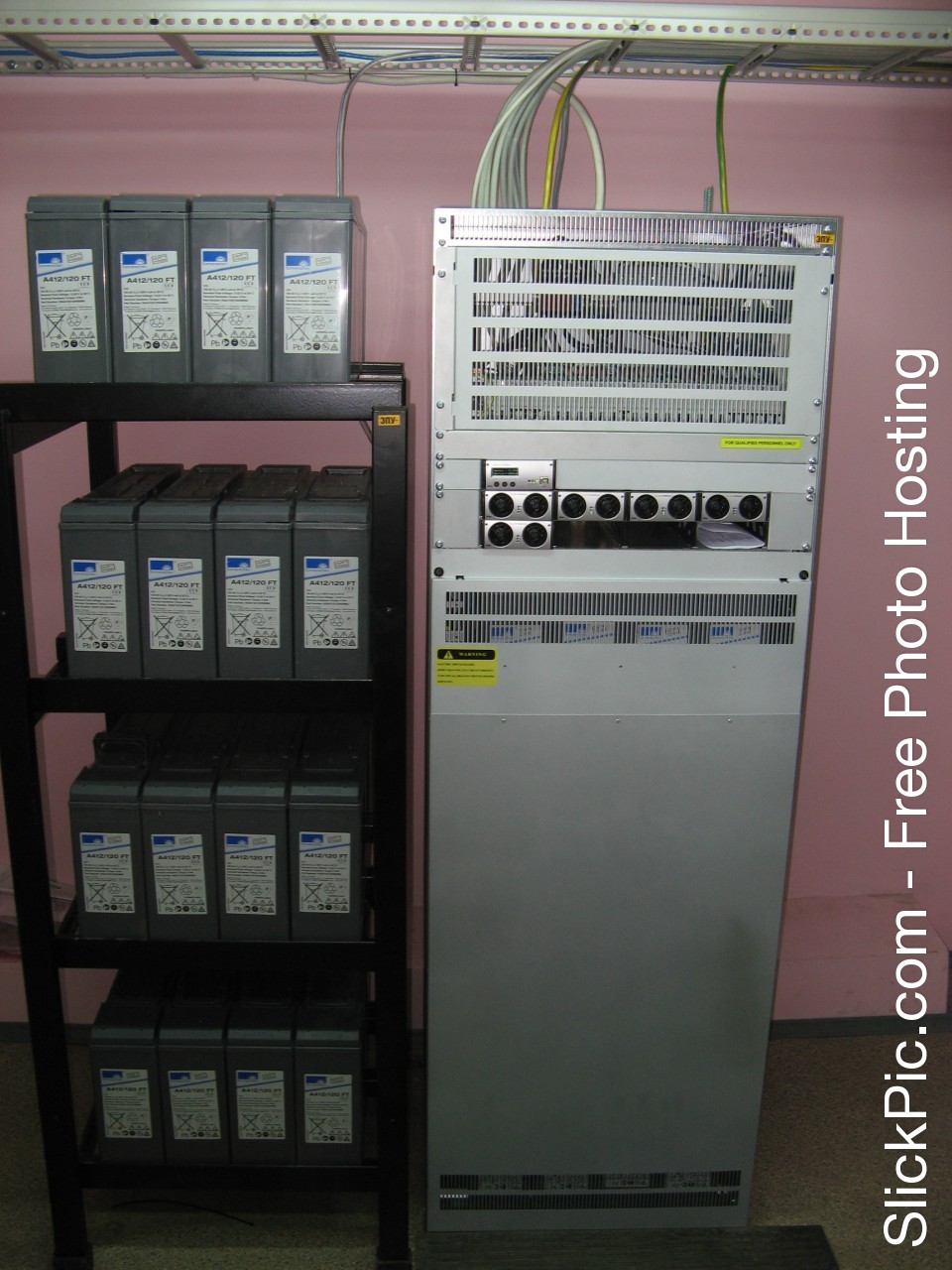
EPU is a metal cabinet 2 meters high with battery racks, a control module (SmartPack), rectifiers, which just converts 220V AC to -48V DC, their power is usually 2 kW to 48V, they can work from 185 - 275V, although at 260V the coolers start to buzz terribly and howl from high voltage, and they have 92% efficiency, the manufacturer reports that the MTBF is 350,000 hoursand, indeed, they rarely break down, its only minus is weight, one rectifier is quite heavy - 2 kilograms and sometimes you have to carry a tool bag with a tool - 10 kg and 3 rectifiers - 6 kg with you in the winter mountains. and another kilogram 5 of every little thing, when the emergency exit and the reason for the shutdown is unknown.
EPU: the
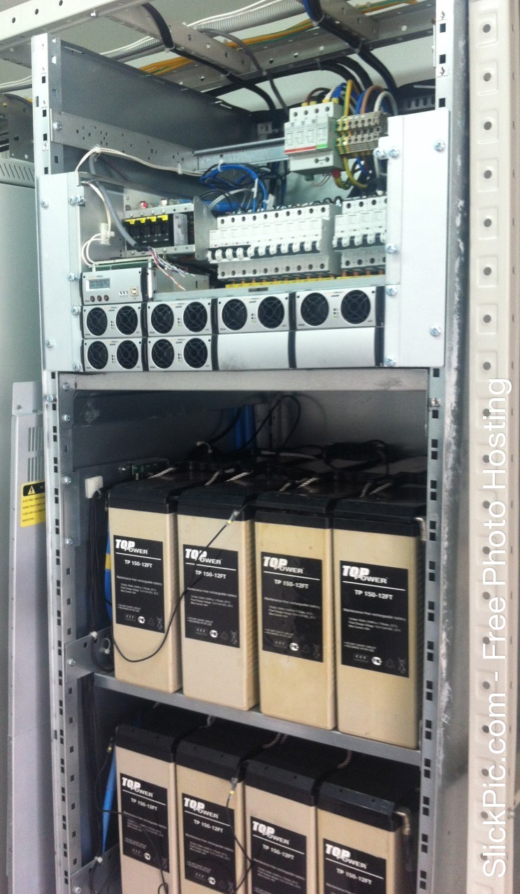
first is the general view of the EPU, the
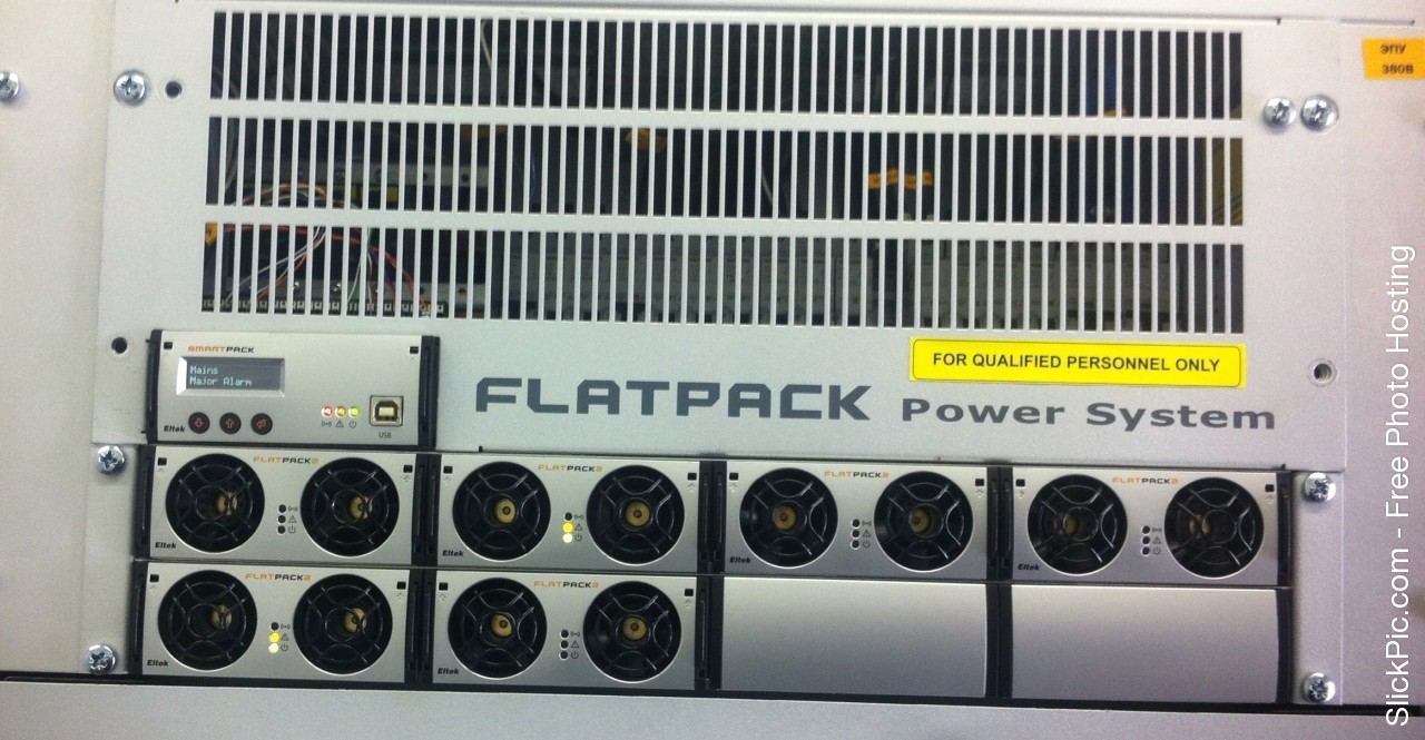
second is the view of the rectifiers and SmartPack, the
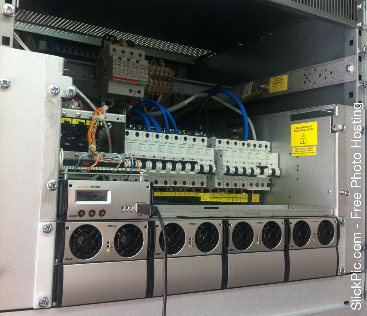
third is the view of the load bus, the left is the priority, the right is the priority.
Rectifier:

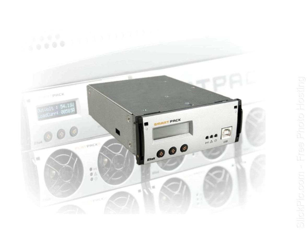
SmartPack:
But they were distracted from the ECU device, the following elements are two contactors and two rows of machines, I will immediately explain why they are needed: the first contactor disconnects the non-priority load (LVLD, load), the second, respectively, the priority (LVBD, battery), in other words, this contactor disconnects the batteries.
The system is designed so that if the station is nodal, that is, a stream comes to it, let's say from the controller, and the stream still leaves from this station, it is divided into several stations, it turns out that the operation of five others depends on our BS, such a station is considered nodal, and here they help contactors.
RRL, SDH and other vehicles are always connected to the bus controlled by the LVBD contactor - a priority bus, and the BS to LVLD is not a priority. Contactors are triggered when a certain parameter is reached - this is the voltage.
For example, the power supply at the junction station disappears (accident, cable damage, the shield burned out), the station starts to work from the battery, there are usually 3-4 groups of 48V, in group 4 of the battery 12 V, the capacity depends on the installed models, on average it is about 500 Ah
There is a load, the batteries run down and the voltage drops as soon as it reaches, say, up to 46V, then the load contactor opens and the BS shuts down (OML Fault alarm), but only the priority load remains in operation: the node station does not work, but the transport remains in operation and our five stations broadcast successfully, then the voltage continues to fall and reaches a critical 43V; irreversible processes in the battery are already starting below, the battery contactor disconnects the priority load - the transport drops and the signal disappears on five other BSs, which By connecting to our. I want to note that from the moment the power is lost and until the batteries are turned off, a different time elapses, depending on the load, how much the equipment consumes and the state of the battery. I know that there were cases and the BS fell after 20 seconds or the node stood for two days and put the batteries in only a third, everything is very individual here. Such a load prioritization system is called separation.
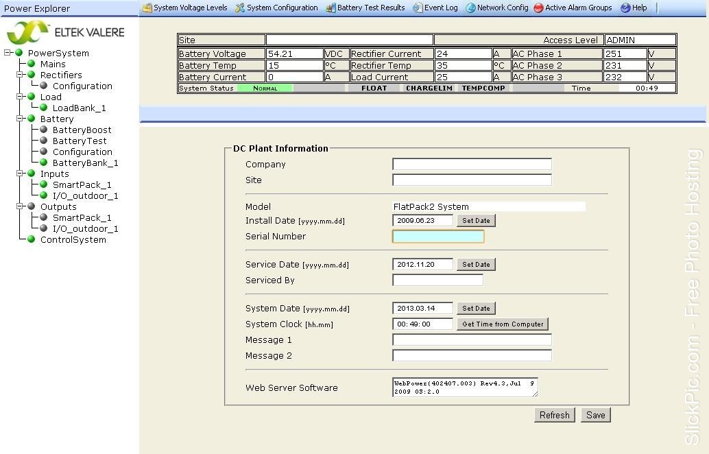
The entire system is controlled by the SmartPack module - the brain of the electronic control unit, all parameters are stored in it. SpartPack has an Ethetnet output with a web muzzle that looks to the local network, so we can perform most of the settings, monitor the status, watch alarms on the rack, by the way, information about alarms on the BS deserves a separate topic.
When servicing a control computer, an engineer connected by a cable to the control module changes the settings, of which there are many.
The main thing is this separation, the alarm alarm setting, for the battery it is the charge current adjustment, temperature compensation, symmetry - the voltage parameter with which you can see on which group the voltage dropped and take measures, for rectifiers - sleep voltage, operating voltage, rectifier current limitation. I note that the rectifiers also have an LED indicator: green - everything is ok, yellow - attention and red when the rectifier is out of order, for example, burned out. All automatic machines, battery terminals are tightened as well, dust and dirt are removed, all defects are recorded and eliminated at the next maintenance.
I will be glad to write new articles about energy in cellular communications!
UPD:
What does the web interface look like:
What does the assembled EPU look like (the junction station therefore connects an additional cabinet with a battery)
All consumers of communication in the base station (BS) are RRL (radio relay part or relay), the base station itself, SDH is equipment that operates from -48 volts and direct current.
380V is suitable for the BS, the task of the power supply installation (EPU) is just to convert the 380V (220V) alternating current into -48V DC. It turns out a "+" on the body of the EPU.
In the main work, Eltek controllers are used; there are several from other manufacturers, but there are few of them, they are old, and difficult to configure. Eltek has FlatPack models and has come to replace her, more flexible in setting up FlatPack 2, which I want to dwell on in more detail.
EPU is a metal cabinet 2 meters high with battery racks, a control module (SmartPack), rectifiers, which just converts 220V AC to -48V DC, their power is usually 2 kW to 48V, they can work from 185 - 275V, although at 260V the coolers start to buzz terribly and howl from high voltage, and they have 92% efficiency, the manufacturer reports that the MTBF is 350,000 hoursand, indeed, they rarely break down, its only minus is weight, one rectifier is quite heavy - 2 kilograms and sometimes you have to carry a tool bag with a tool - 10 kg and 3 rectifiers - 6 kg with you in the winter mountains. and another kilogram 5 of every little thing, when the emergency exit and the reason for the shutdown is unknown.
EPU: the
first is the general view of the EPU, the
second is the view of the rectifiers and SmartPack, the
third is the view of the load bus, the left is the priority, the right is the priority.
Rectifier:
SmartPack:
But they were distracted from the ECU device, the following elements are two contactors and two rows of machines, I will immediately explain why they are needed: the first contactor disconnects the non-priority load (LVLD, load), the second, respectively, the priority (LVBD, battery), in other words, this contactor disconnects the batteries.
The system is designed so that if the station is nodal, that is, a stream comes to it, let's say from the controller, and the stream still leaves from this station, it is divided into several stations, it turns out that the operation of five others depends on our BS, such a station is considered nodal, and here they help contactors.
RRL, SDH and other vehicles are always connected to the bus controlled by the LVBD contactor - a priority bus, and the BS to LVLD is not a priority. Contactors are triggered when a certain parameter is reached - this is the voltage.
For example, the power supply at the junction station disappears (accident, cable damage, the shield burned out), the station starts to work from the battery, there are usually 3-4 groups of 48V, in group 4 of the battery 12 V, the capacity depends on the installed models, on average it is about 500 Ah
There is a load, the batteries run down and the voltage drops as soon as it reaches, say, up to 46V, then the load contactor opens and the BS shuts down (OML Fault alarm), but only the priority load remains in operation: the node station does not work, but the transport remains in operation and our five stations broadcast successfully, then the voltage continues to fall and reaches a critical 43V; irreversible processes in the battery are already starting below, the battery contactor disconnects the priority load - the transport drops and the signal disappears on five other BSs, which By connecting to our. I want to note that from the moment the power is lost and until the batteries are turned off, a different time elapses, depending on the load, how much the equipment consumes and the state of the battery. I know that there were cases and the BS fell after 20 seconds or the node stood for two days and put the batteries in only a third, everything is very individual here. Such a load prioritization system is called separation.
The entire system is controlled by the SmartPack module - the brain of the electronic control unit, all parameters are stored in it. SpartPack has an Ethetnet output with a web muzzle that looks to the local network, so we can perform most of the settings, monitor the status, watch alarms on the rack, by the way, information about alarms on the BS deserves a separate topic.
When servicing a control computer, an engineer connected by a cable to the control module changes the settings, of which there are many.
The main thing is this separation, the alarm alarm setting, for the battery it is the charge current adjustment, temperature compensation, symmetry - the voltage parameter with which you can see on which group the voltage dropped and take measures, for rectifiers - sleep voltage, operating voltage, rectifier current limitation. I note that the rectifiers also have an LED indicator: green - everything is ok, yellow - attention and red when the rectifier is out of order, for example, burned out. All automatic machines, battery terminals are tightened as well, dust and dirt are removed, all defects are recorded and eliminated at the next maintenance.
I will be glad to write new articles about energy in cellular communications!
UPD:
What does the web interface look like:
What does the assembled EPU look like (the junction station therefore connects an additional cabinet with a battery)