Calculation of wave processes in the hydraulic line by the method of characteristics

Hi, Habr! In this article I will talk about the creation of a mathematical model of a long pipeline for the CAE-program SimulationX in the language of Modelica. We will talk about the calculation of wave processes (pressure pulsations, water hammer, etc.) in the hydraulic line using the method of characteristics. Despite the fact that this method is quite old, in runet there is quite a bit of information about its use for solving applied problems.
Under the cut, I will try to explain why the wave processes in pipelines need to be considered at all, to highlight the problems I encountered while programming and at the end I will compare the process of pressure pulsations when a three-plunger high-pressure water pump operates on a simple long pipeline in the model and on the URACA bench in Germany.
Introduction
In engineering practice, wave processes in pipelines, as a rule, pay very little attention. The most famous example when wave processes ruin an engineer’s life is a hydraulic shock:
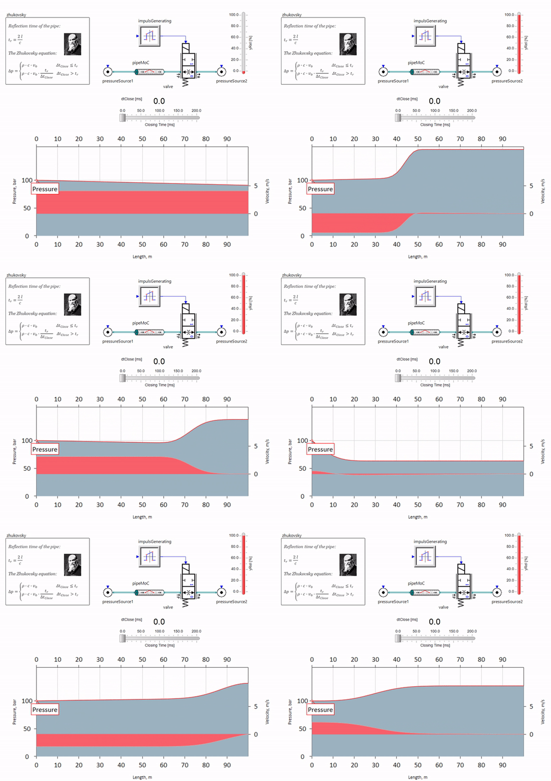
When a valve closes quickly at the end of the pipeline downstream, a pressure wave arises that moves upstream with a local sound velocity (approximately 1500 m / s for water) , is reflected from a source of constant pressure, goes back to the valve and is reflected from it, this time with a negative sign. This process is repeated until all energy is consumed by friction, and until then the valve and the entire pipeline experience shock loads, the amplitude and frequency of which depend on the length of the pipeline and the initial velocity of the fluid.
A water hammer with the accuracy required for solving practical problems was described at the end of the 19th century by Nikolay Zhukovsky, thus solving the problem of accidents on the Moscow water pipeline. Since then, the formula for calculating the pressure jump during the rapid closing of the valve is called the Zhukovsky formula all over the world :
Water hammer in practice manifests itself, as a rule, with pipeline lengths from one hundred meters. At lengths below, it is already difficult to find hydraulic equipment that would manage to close faster than the pressure wave travels from the valve and back (the condition of the hydraulic impact). Nevertheless, even relatively short pipelines can still ruin the lives of engineers if the system has a source of flow rate pulsations (for example, a positive displacement pump with a finite number of plungers).
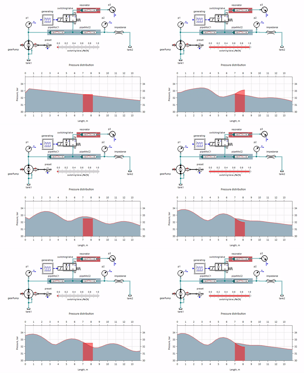
The gif is shown the beneficial effect of a piece of the pipeline with a length of just over a meter. Its length is equal to a quarter of the pressure wavelength; therefore, when it is connected to the main pipeline, a so-called a standing wave, which in antiphase strikes at the source of the pulsations and suppresses them in this way (this is the so-called quarter-wave pulsation damper). It is clear that in case of unsuccessful set of circumstances, the effect may be reversed.
In my practice, I have long tried to dismiss wave processes, since their calculation required a deepening of the matan and numerical methods, which throughout my studies I treated with condescending disregard. But when once I saw with my own eyes that the standard advice (to put the RVD everywhere, the hydraulic accumulator, to organize a suction pump) does not help either to get rid of the pulsations on the stand, nor, moreover, bring them closer to understanding the processes that are taking place, I had to go deep into matane . Especially, to my shame, my supervisor has already started writing a C ++ model of the pipeline for me.
1. One-dimensional model of the hydraulic line in distributed parameters
The main problem that makes traditional single-dimensional models described by ordinary differential equations go out of the comfort zone is that the simplest pipeline, even with the most brutal assumptions (completely filled with liquid, constant cross-section along the length, fluid velocity averaged over the section, heat exchange processes considered) is described by differential equations in distributed parameters (Euler equations, only taking into account the mass force and friction in the right side of the second avneniya):
Where
Those. Now you need to integrate not only in time
In the case of liquids, you can simplify your life a little more if you rewrite the equations from conservative variables into primitive variables (speed and pressure):
Where
Now, if we assume that the speed of sound is substantially greater than the velocity of the fluid
To solve these equations, it is necessary in one way or another to get rid of the differentiation along the spatial coordinate
Now these equations can be solved as ordinary differential equations, breaking the pipe length into a set of finite volumes. This is done , for example, in the Simscape package, in MATLAB Simulink, so the problem was solved until recently in SimulationX .
Something like this, of course, can be calculated, but the numerical oscillations arising in this case strongly interfere:
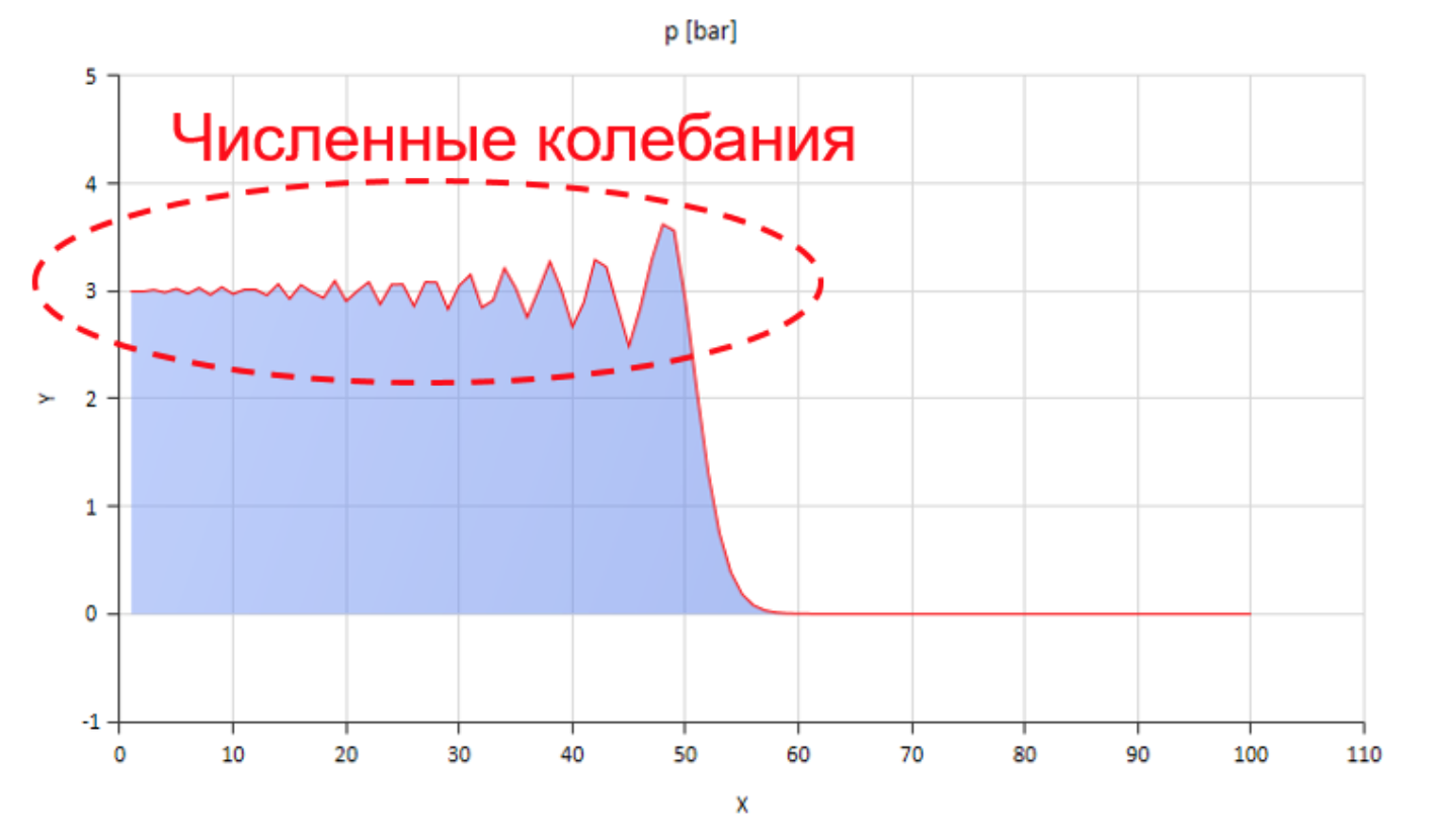
The figure shows the front of a pressure wave moving from left to right.
You can deal with these fluctuations, for example, by introducing numerical diffusion, but then the wave propagation velocity is significantly distorted. You can increase the friction (especially increasing its non-stationary component), but then the model ceases to reflect the physical essence.
It is best to use another method of transforming equations in distributed parameters into ordinary differential equations, for example, the method of characteristics.
2. Method of characteristics
Wikipedia on request “Method of performance” recommends:
... to find such characteristics along which the partial differential equation turns into an ordinary differential equation. As soon as ordinary differential equations are found, they can be solved along the characteristics and the solution found can be turned into a solution of the original partial differential equation.It’s like a philosopher’s stone, but instead of turning metals into gold, we turn partial differential equations into ordinary ones, and vice versa. The question arises: “how can we put this into practice?”, And more preferably, than the medieval alchemists did it ...
First, let's look at the problem statement. At our disposal at the initial moment of time there is some distribution of pressures and velocities along the length of the pipe. First we divide the pipe into a finite number of elements and for each face we assign its own pressure value.
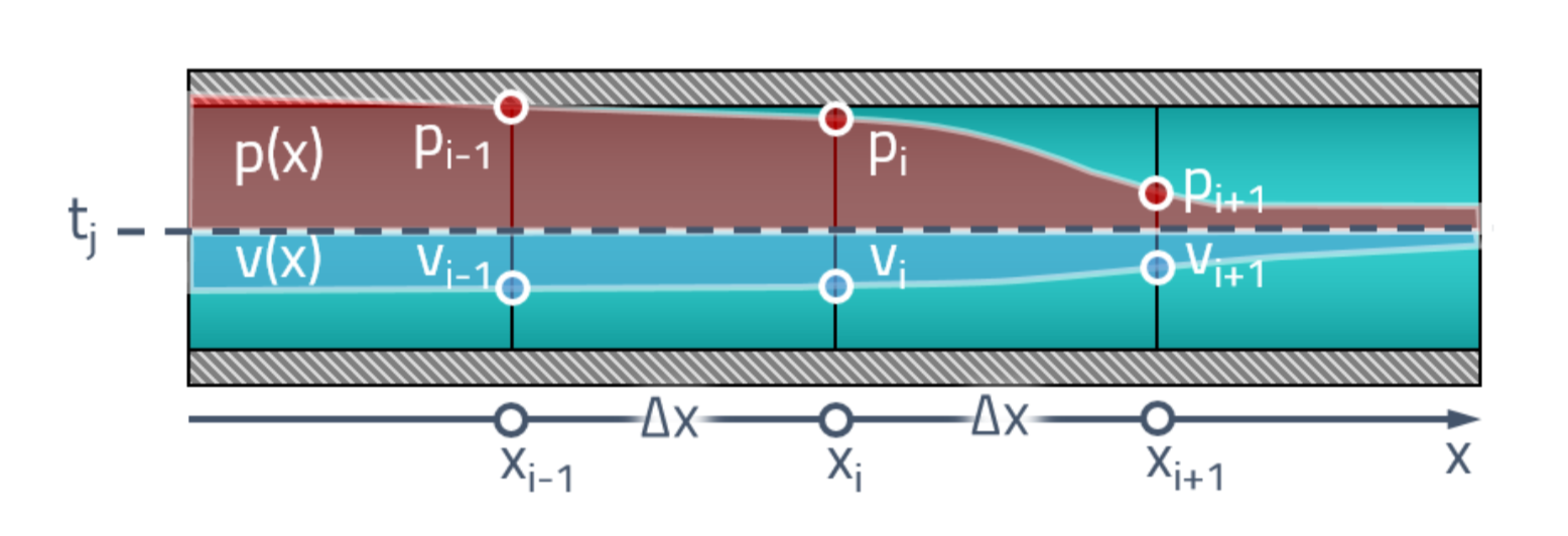
We are interested in how the values at these points change in time

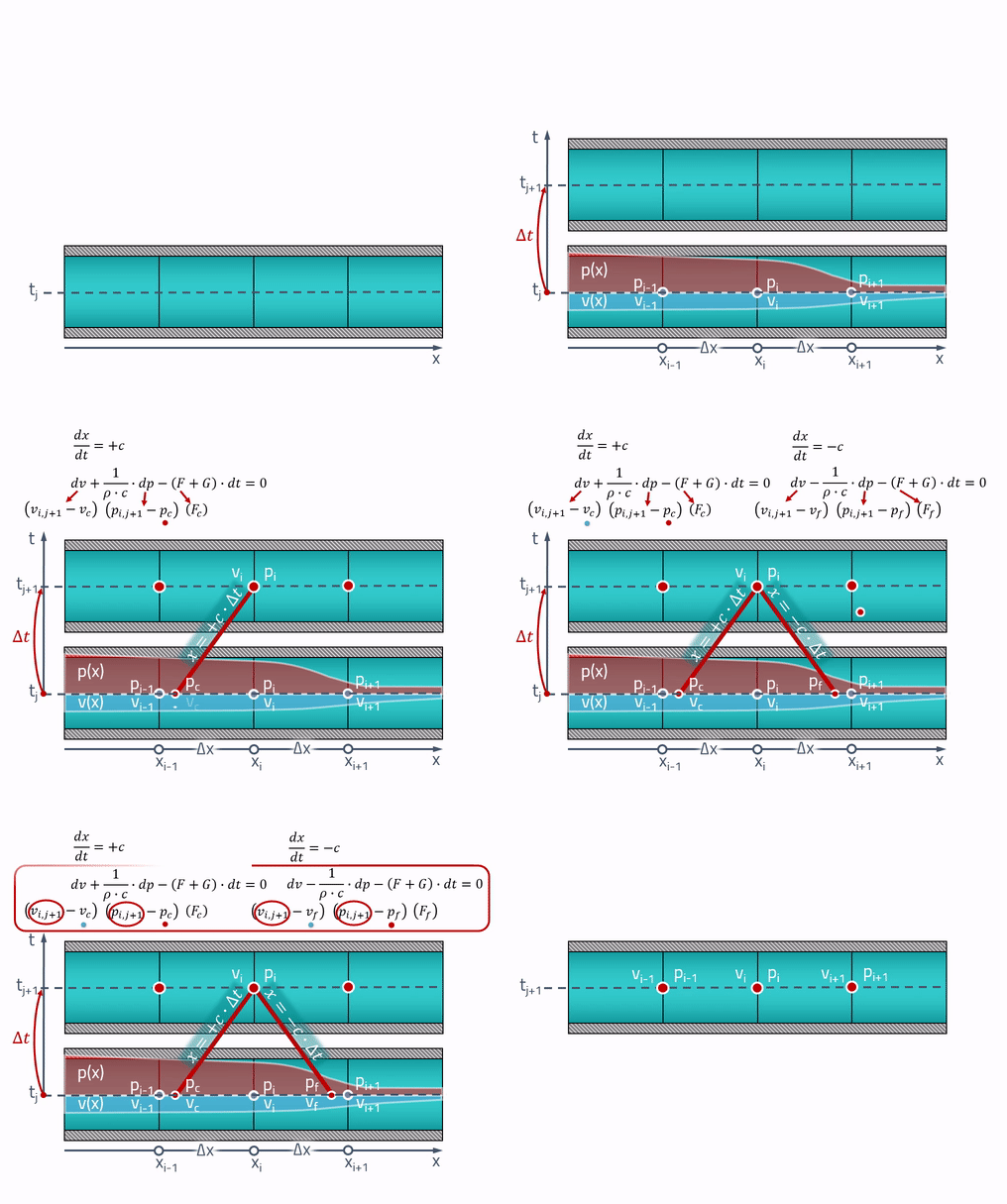
This is where the “magic” characteristics will be useful to us! The worker-peasant explanation is that all changes in the pipe occur at the speed of sound. The pressure and speed at the current time point

From a point, two symmetrical lines are drawn, the angle of inclination of which is determined by the speed of sound. These are the very characteristics along which the partial differential equations turn into ordinary differential equations. If we call the points at which the characteristics intersect with the state of the pipe in the past as
The values of pressures and velocities at these points can be obtained by linear interpolation between the values of the state parameters on the grid:

It is important to consider that these points must always be within neighboring cells! For this, the time step must satisfy the Courant-Friedrichs-Levy criterion (CFL):
Now, even the simplest difference scheme can be applied to these equations:
In the resulting system of two equations, two unknowns: pressure
To fix, I’ll give an animation of the performance of the method of characteristics:
In fact...
… скорость звука зависит от давления жидкости. В этом случае характеристики, строго говоря уже не будут прямыми линиями, а для того, чтобы найти давление, нужно уже будет знать скорость звука, которая от этого давления зависит. Т.е. схема будет уже неявной.
При создании модели, я принял допущение, что скорость звука слабо меняется от шага к шагу. Для жидкости это справедливо в случае низкого газосодержания и при отсутствии кавитации. Чтобы быть уверенным в результате, модель лучше использовать при давлениях от 10 бар.
3. Experiment
I had the opportunity to finally bring to mind the model already when I started working in the company ESI ITI GmbH in Dresden. Once, I received a ticket in the Helpdesk, where URACA engineers complained that they could not achieve convergence with the experiment with our “old” pipe.
They make high-pressure water plunger pumps, such enormous “Karchers”, and would like to be able to predict possible resonance effects due to, among others. wave processes in the pipeline. The problem is that such pumps, as a rule, have quite a few plungers and they work at low revs (250-500 rpm):

Because of this, and also due to the influence of the compressibility of the fluid, the output is very uneven innings:

Breaks and non-linearities make linearization and model analysis in the frequency domain difficult, and CFD calculations for such a task are gun shooting at sparrows. In addition, they already had models in SimulationX, where they took into account the dynamics of the mechanical part of the pump, the elasticity of the frame, the characteristics of the electric motor, so it would be interesting to see how the pipeline would affect this.
The layout of the test bench is quite simple:
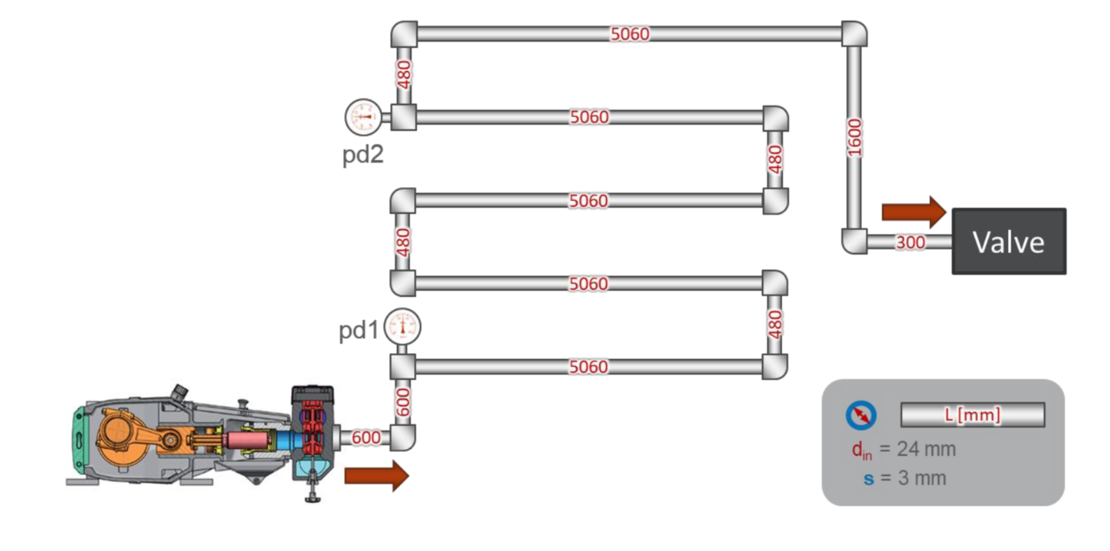
There is a simple pipeline with a total length of about 30 meters. At the beginning of the pipeline, a pressure sensor pd1 is installed, at a distance of 22 meters from it - a pressure sensor pd2. At the end of the pipeline valve, which adjusts the pressure in the system.
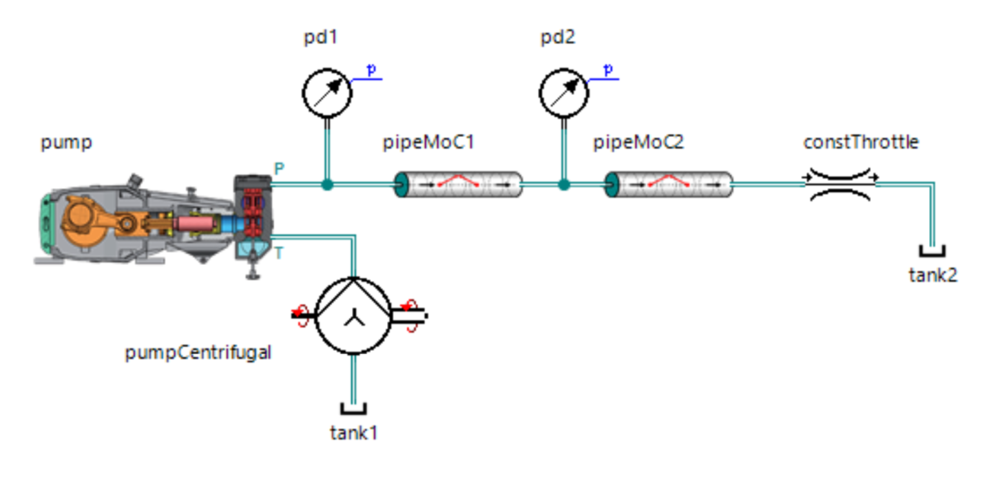
I offered to test the beta version of my model, as a result, the following model was built in SimulationX:
Even I was pleasantly surprised by the results:
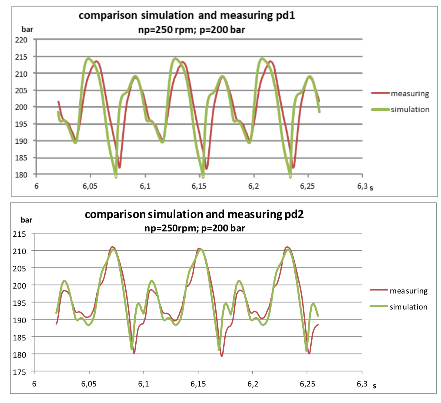
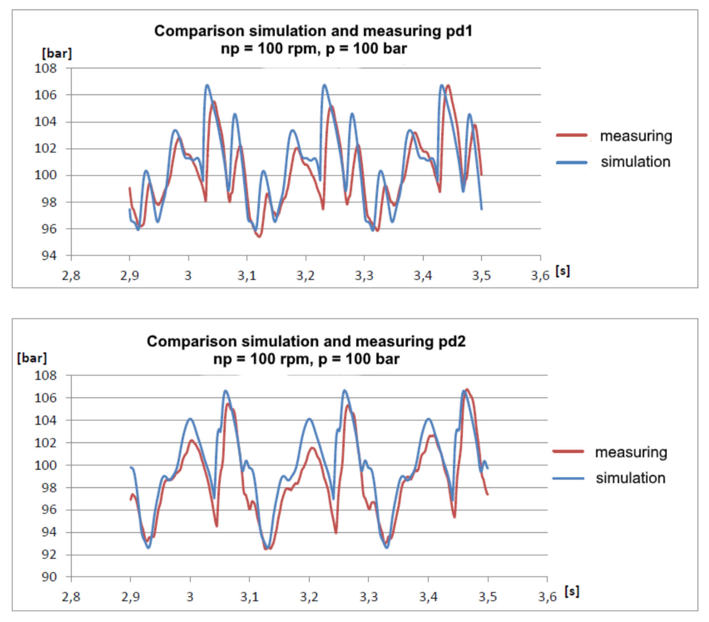
It can be seen that the model is slightly worse damped, which is understandable provided that it does not take into account hydraulic resistances. Nevertheless, the main harmonics coincide quite well and allow one to predict the pressure amplitudes with fairly good accuracy.
This experience made it possible to quickly launch a new model of the hydraulic line into the SimulationX release, and I plunged into this topic and did not notice how I wrote down the model of the pneumatic line with the student-trainee, where everything was much more interesting. There, I had to use a method based on the Godunov method, which in turn is based on solving the Riemann problem of the decay of an arbitrary discontinuity, but about that some other time ...
Literature
- In the Russian literature, the method of characteristics for engineering applications is best described in the book “Hydromechanics”, D. N. Popov, S. S. Panaiotti, M. V. Ryabinin.
- In its publication Pipeline simulation for high pressure water plunger pumpI considered in more detail the problems of the docking of the method of characteristics and the solver of ODEs.«Dr.-Ing.(Rus) Maxim Andreev, Dipl.-Ing. Uwe Grätz and Dipl.-Ing. (FH) Achim Lamparter», The 11th International Fluid Power Conference, 11. IFK, March 19-21, 2018, Aachen, Germany, за текстом обращайтесь в личку
- Who has access to German libraries, the best overview of methods for solving hyperbolic equations applied to hydraulic lines, which I have met, is contained in the following dissertation: Beck, M., Modellierung und Simulation der Wellenbewegung in kavitierenden Hydraulikleitungen, Univ. Stuttgart, Germany, 2003.
- Classics of the genre on hyperbolic equations in general: Randall J. Leveque, Finite Volume Methods for Hyperbolic Problems, Cambridge University Press, Cambridge, United Kingdom, 2002.
