Simple in-circuit microcontroller programmer LPC. Features of in-circuit programming. Part two
In my first article I described a simple programmer circuit , today I will tell you how to connect it to a programmable device.
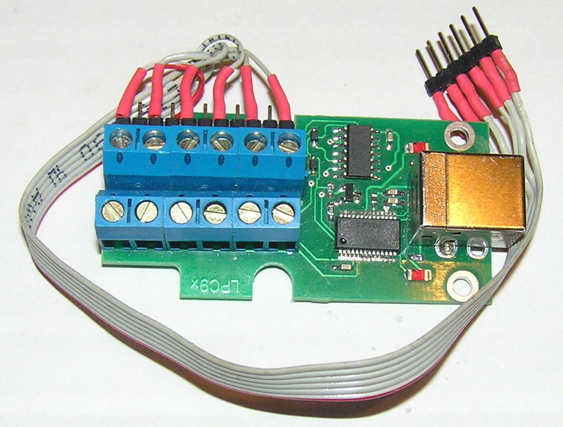
Fig. 1. The appearance of the programmer.
In the good old days, when microcontrollers with programmable memory of FLASH-based programs were just beginning to appear, their programming was carried out via a parallel interface. At the same time, more than 20 pins could be used for programming, and often it was necessary to use an increased voltage of 12 volts or more. Microcontrollers were then produced in output DIP cases. They were programmed mainly by inserting them into high-quality programmer panels, and only then they were soldered into the device. However, over time, the transition began to programming on a serial channel, while for programming only 4-5 signal legs were already used. In addition, microcircuits began to be manufactured in completely exotic cases. Reliable sockets for such cases sometimes could cost almost more than the programmer itself! There was an opportunity and the need to reprogram microcontrollers without evaporating from the circuit - in-circuit programming. This is very convenient for debugging a program. In addition, it became possible to complete the installation of the board, and to carry out programming already when setting up and releasing the device. This is especially convenient when working with contract manufacturers - there is a guarantee that program code will not leak.
Today, most microcontroller devices use in-circuit programming. To illustrate, consider the microcontrollers of the LPC2xxx family.
These microcontrollers have a built-in bootloader that allows you to flash FLASH memory by in-circuit programming. For data transfer, serial port 0 is used - RXD0 and TXD0 pins. The algorithm for entering the programming mode is very simple, for this only two additional signal legs are used - P0.14 and Reset.
Port P0.14 is set to a low logic level, in other words, it closes to ground, while a high logic level must be present at the Reset pin. It is worth noting, however, that exceptions are possible if the user program was previously launched, in which, for example, a watchdog timer is involved. Therefore, the most reliable algorithm for entering the microcontroller into the programming mode is as follows.
Before turning the power on, short the terminals P0.14 and Reset to ground. Apply power, wait until it is set to its nominal value. Set Reset to a high logic level, wait at least a few milliseconds, and set a high level to P0.14.
For the successful use of this feature, it is necessary to observe several not complicated rules, which are easier to demonstrate using the example of a programmer connecting to a device based on a microcontroller from the LPC 214x series. For programming, we will use the programmer described in the previous article.

Fig. 2. The connection diagram of the programmer.
We begin the overview of the circuit. Port P0.14 is pulled up to power with the help of resistor R4, so that when the device is turned on in normal mode, a high level appears on it and, accordingly, the user program is launched. In the LPC_RESET circuit there is a pull-up register for power and a capacitor for ground. For normal operation, their ratings must be selected depending on the power source used. The fact is that when the device is connected to power, the voltage on it reaches the rated voltage not instantly, but gradually, as the filter capacities are charged. For normal operation of the device, it is necessary that the microcontroller starts only after reaching a certain power level, in modern microcontrollers special circuits are provided for this, but rely on them, and it’s not bad, as practice shows, with a slow increase in the supply voltage, these circuits may not work correctly. At the moment of supply voltage supply, the capacitor C2 starts to charge and the voltage on it is kept for a while at a low level. It is advisable to select the values of the circuit R5, C2 in such a way that a high level at the RESET input does not appear earlier than the supply voltage of the microcontroller reaches a voltage of 2.6 volts.
The programming process occurs at a low level at the RESET input, while all the input / output ports of the microcontroller are transferred to a high-resistance state. If the ports of your microcontroller are used to control any nodes, for example, power switches or controlled voltage stabilizers, it is necessary to ensure that they are pulled to the desired logical level during programming, otherwise big troubles can occur, up to the failure of the board itself and the devices controlled by it.
In our example, the zero COM port is used not only for programming, but also for data exchange via the RS485 interface. To do this, use the node on the D2 chip. Typically, the D2 chip is constantly on in receive mode, while it generates a signal at the RXD input of the microcontroller. In programming mode, this signal will interfere with the programmer, so that this does not happen, the circuit provides resistance R1 and R3. R1 puts the D2 receiver in an inactive state - the output R0 goes into a high resistance state and does not interfere with data transfer to the programmer, and R3 turns off the transmitter so that incorrect data does not arrive through the RS-485 interface driver.
If you intend to use sufficiently long wires for programming, or there is a possibility that users may not be reprogramming the device, those who do not have sufficient qualifications should worry about protecting the programmable microcontroller from static and voltage surges. For example, I had a case when the device had to be replaced by a microcontroller 4 times due to the crooked “programmers”! The simplest protection can consist of diodes or zener diodes that limit the voltage and are connected in series with resistors with a small resistance. For example, as shown in figure 3.

Fig. 3. Connection diagram of the programmer with protective circuits.
It remains to add that for programming microcontrollers of the LPC2xxx family based on the ARM7TDMI core, pin 3 of the programmer is connected to port P0.14. For programming microcontrollers of the LPCxxx family based on the ARM7 Cortex core, pin 3 of the programmer is connected to port P2.10.
The theme of programming microcontrollers and other devices, despite its apparent simplicity, is very multifaceted and full of nuances. However, for our case, it
remains to talk about the software and the programming features of the LPC900 series.
PSThis article is intended mainly for beginner embedders, so I apologize for the fact that I may unnecessarily explain in detail some obvious things for the pros.
Fig. 1. The appearance of the programmer.
In the good old days, when microcontrollers with programmable memory of FLASH-based programs were just beginning to appear, their programming was carried out via a parallel interface. At the same time, more than 20 pins could be used for programming, and often it was necessary to use an increased voltage of 12 volts or more. Microcontrollers were then produced in output DIP cases. They were programmed mainly by inserting them into high-quality programmer panels, and only then they were soldered into the device. However, over time, the transition began to programming on a serial channel, while for programming only 4-5 signal legs were already used. In addition, microcircuits began to be manufactured in completely exotic cases. Reliable sockets for such cases sometimes could cost almost more than the programmer itself! There was an opportunity and the need to reprogram microcontrollers without evaporating from the circuit - in-circuit programming. This is very convenient for debugging a program. In addition, it became possible to complete the installation of the board, and to carry out programming already when setting up and releasing the device. This is especially convenient when working with contract manufacturers - there is a guarantee that program code will not leak.
Today, most microcontroller devices use in-circuit programming. To illustrate, consider the microcontrollers of the LPC2xxx family.
These microcontrollers have a built-in bootloader that allows you to flash FLASH memory by in-circuit programming. For data transfer, serial port 0 is used - RXD0 and TXD0 pins. The algorithm for entering the programming mode is very simple, for this only two additional signal legs are used - P0.14 and Reset.
Port P0.14 is set to a low logic level, in other words, it closes to ground, while a high logic level must be present at the Reset pin. It is worth noting, however, that exceptions are possible if the user program was previously launched, in which, for example, a watchdog timer is involved. Therefore, the most reliable algorithm for entering the microcontroller into the programming mode is as follows.
Before turning the power on, short the terminals P0.14 and Reset to ground. Apply power, wait until it is set to its nominal value. Set Reset to a high logic level, wait at least a few milliseconds, and set a high level to P0.14.
For the successful use of this feature, it is necessary to observe several not complicated rules, which are easier to demonstrate using the example of a programmer connecting to a device based on a microcontroller from the LPC 214x series. For programming, we will use the programmer described in the previous article.
Fig. 2. The connection diagram of the programmer.
We begin the overview of the circuit. Port P0.14 is pulled up to power with the help of resistor R4, so that when the device is turned on in normal mode, a high level appears on it and, accordingly, the user program is launched. In the LPC_RESET circuit there is a pull-up register for power and a capacitor for ground. For normal operation, their ratings must be selected depending on the power source used. The fact is that when the device is connected to power, the voltage on it reaches the rated voltage not instantly, but gradually, as the filter capacities are charged. For normal operation of the device, it is necessary that the microcontroller starts only after reaching a certain power level, in modern microcontrollers special circuits are provided for this, but rely on them, and it’s not bad, as practice shows, with a slow increase in the supply voltage, these circuits may not work correctly. At the moment of supply voltage supply, the capacitor C2 starts to charge and the voltage on it is kept for a while at a low level. It is advisable to select the values of the circuit R5, C2 in such a way that a high level at the RESET input does not appear earlier than the supply voltage of the microcontroller reaches a voltage of 2.6 volts.
The programming process occurs at a low level at the RESET input, while all the input / output ports of the microcontroller are transferred to a high-resistance state. If the ports of your microcontroller are used to control any nodes, for example, power switches or controlled voltage stabilizers, it is necessary to ensure that they are pulled to the desired logical level during programming, otherwise big troubles can occur, up to the failure of the board itself and the devices controlled by it.
In our example, the zero COM port is used not only for programming, but also for data exchange via the RS485 interface. To do this, use the node on the D2 chip. Typically, the D2 chip is constantly on in receive mode, while it generates a signal at the RXD input of the microcontroller. In programming mode, this signal will interfere with the programmer, so that this does not happen, the circuit provides resistance R1 and R3. R1 puts the D2 receiver in an inactive state - the output R0 goes into a high resistance state and does not interfere with data transfer to the programmer, and R3 turns off the transmitter so that incorrect data does not arrive through the RS-485 interface driver.
If you intend to use sufficiently long wires for programming, or there is a possibility that users may not be reprogramming the device, those who do not have sufficient qualifications should worry about protecting the programmable microcontroller from static and voltage surges. For example, I had a case when the device had to be replaced by a microcontroller 4 times due to the crooked “programmers”! The simplest protection can consist of diodes or zener diodes that limit the voltage and are connected in series with resistors with a small resistance. For example, as shown in figure 3.
Fig. 3. Connection diagram of the programmer with protective circuits.
It remains to add that for programming microcontrollers of the LPC2xxx family based on the ARM7TDMI core, pin 3 of the programmer is connected to port P0.14. For programming microcontrollers of the LPCxxx family based on the ARM7 Cortex core, pin 3 of the programmer is connected to port P2.10.
The theme of programming microcontrollers and other devices, despite its apparent simplicity, is very multifaceted and full of nuances. However, for our case, it
remains to talk about the software and the programming features of the LPC900 series.
PSThis article is intended mainly for beginner embedders, so I apologize for the fact that I may unnecessarily explain in detail some obvious things for the pros.