Writing a Gameboy Emulator, Part 3
- Tutorial
Hello!
In the previous part of this series of articles, we completed work on the critical components of our emulator. For completeness, in this article we will consider the DMG sound system.
We are writing a Gameboy emulator, part 1
We are writing a Gameboy emulator, part 2
We are writing a Gameboy emulator, part 3
Before you start, here is a link to the Cookieboy repository where you can find its source code and the latest build.
Sound channels 1 and 2
Sound channel 3
Sound channel 4
Implementation
Testing
What's next
Conclusion
Each channel puts at its disposal a series of registers that allow you to control these components and the channel itself. They (registers) are numbered in a certain way - NRXY, where X is the channel number (1, 2, 3, 4), Y is the register number. Where necessary, I will omit the channel number and simply write X.
The following audio channels are available on the DMG:
The first two channels are identical and differ only in the set of modulation components.
The third channel allows you to play an arbitrary waveform from a special memory area in the I / O ports - Wave Pattern RAM section. Thus, it is possible to reproduce a digital sound of arbitrary content by timely updating the specified memory area. Some manage to reproduce something similar to speech.
The fourth channel allows you to generate noise of a different nature. Well suited for voicing various special effects.
Here is a simplified sound shaping scheme in DMG:

After passing through all the components of the modulation, the audio signal enters the mixer, which mixes the various channels and outputs to one of the outputs. S01 - the right ear. S02 - left ear. The mixing operation is reduced to a simple addition of signals from all sources for a specific output - NR51 indicates where and which channels should be output. Further, the volume for each of the outputs is taken into account - the signal after mixing is multiplied by the volume value of this output in the register NR50 plus 1.
Do not try to fully understand this scheme - along the way everything that is drawn on it will be considered in more detail.
NR50 and NR51 are common registers. In addition to them, there is a common register NR52, which contains a flag to mute all sound, as well as bits showing the status of sound channels. You can only change the mute flag. Status bits are read-only and constantly updated.
If the sound is muted in register NR52, then the following occurs:
Speaking of the availability of register bits. Pay attention to which bits are not used or are not readable. When trying to read registers from the outside, you need to set to one all bits that are not used or are not available for reading. Test ROMs test this. No need to change the register itself. Sound components, of course, have full access to the registers.
All sound generating components are synchronized with the clock. To generate sound waves of a certain frequency, the clock generator itself is used. A separate Frame Sequencer clock operating at a frequency of 512 Hz is allocated for modulating components. It also works from the main clock, but allows you to generate low-frequency samples. The Sweep Unit uses a frequency of 128 Hz. For Length Counter - 256 Hz. For Envelope Unit - 64 Hz. Here's what the process of this clock generator looks like, where each line means one Frame Sequencer sample:
The table indicates which Frame Sequencer samples generate a sample for the modulation components. It turns out that it cycles through such a sequence of samples, which gives us 8 possible states of the Frame Sequencer (we number them from 0 to 7). It is important to consider with what phase the readings for the components occur. It is also worth considering that when the sound starts (flag in the NR52 register), the Frame Sequencer starts from state 1. It is very important to make it clear to the modulation components that you changed the state of the Frame Sequencer. At one time, I barely found this error, due to which one of the test ROMs could not pass.
Having dealt with the general device, we turn to the consideration of each specific channel.
And so, what is a square wave. The figure below shows just such a wave.

It is not particularly important where the time axis is. My emulator uses a wave that generates the segments “there is a signal” (1-2, 3-4, 5-6), “there is no signal” (0-1, 2-3, 4-5). It could be done differently and put the time axis in the middle, but this will only complicate the implementation, and the result will be identical.
In this figure, the signal duty cycle is 2, because segments with different amplitudes have the same duration. DMG allows you to generate rectangular waves with different duty cycle values, although it is customary to use the reciprocal duty cycle factor in the documentation - duty cycle. It is by the way and more visual, and we will use it. The choice is given from 4 different values of the duty cycle - 0.125, 0.25, 0.5, 0.75. The duty cycle does not affect the frequency, but only on the nature of the signal. The figure below shows the differences between the signals at different duty cycle and the same frequency.

4 values are provided, although, in fact, 3 values are provided - duty cycle 0.25 and 0.75 give different-looking waves, but their sound is identical. When reproducing sound, the change in amplitude is of importance, which has the same character with fill factors 0.25 and 0.75.
The duty cycle value is contained in the register NRX1 in the upper two bits.
Naturally, we need to know what frequency the signal should be generated. For this, the registers NRX3 and NRX4 are used. The frequency is indicated by a number 11 bits long - the lower 8 bits are in the NRX3 register, the most significant 3 bits are in the NRX4 register. Thus, the frequency can range from 0 to 2047, but these values do not apply to the actual frequency of the sound. To translate these values into the real frequency, you must use the following formula:
F = 4194304 / (32 * (2048 - X)) Hz,
where X is the frequency from the registers NRX3 and NRX4, F is the frequency of sound.
Thus, the frequency of sound lies in the range from 64 Hz to 131 072 Hz. Do not worry about such high frequencies - not only will it be quite difficult for us to properly generate a sound of such a frequency (according to Kotelnikov's theorem, the sampling frequency should be more than 262 144 Hz); so everything is complicated by the fact that our technology is not able to reproduce this, and our ears are not able to hear. A more real range is limited to 22,000 Hz - this roughly corresponds to the upper limit of the dynamic range of human hearing and it is not at all accidental for most speaker systems. And for such frequencies, the usual sampling rate of 44 100 Hz is enough for us.
The formula above is usually given in the documentation as given, but it would be nice to understand why it is calculated that way. Let's look again at the sound system operation scheme, there is a Wave generator component there. It contains a timer with which a wave of the desired frequency is generated. The period of this timer is 4 * (2048 - X). For the wave to go through the full period, the timer must make 8 counts, which gives us the cherished 32 * (2048 - X) - this is the value of the full period of the wave.
The mentioned timer with proper implementation will allow you not to worry about frequency translations. If the timer in the emulator is synchronized with the processor in the same way as all other components,
then everything will work by itself. Formula 4 * (2048 - X) gives the timer period in ticks.
For 8 samples of this timer, the sound wave will pass the full period. Now back to the fill factor. He dictates the nature of the change of the wave during its period. The following values are given in the documentation (1 and 0 in the right column means, respectively, “there is a signal” and “there is no signal”):
In addition to the frequency, other data is also stored in the NRX4 register. Here is the way its structure:
If bit 6 is cleared, the sound is played endlessly. If the bit is set, then Length Counter comes into play.
Restart bit 7 does just that. If 1 is written to it, then the channel restarts. This may seem strange for a channel that reproduces an infinite periodic signal, but in reality it is more important for the modulation components. About them later. In addition, the above waveforms allow you to generate the correct signal - when you restart the channel, the signal period also starts from the very beginning according to the specified forms.
This is all you need to know about channels 1 and 2 in general. Next, modulation components come into play. Despite the fact that each channel contains its own modulation components, their operating principle is identical. Now we will consider all the components of the modulation (channel 1 contains all of them), so as not to be repeated anymore.
Periods are indicated in milliseconds, and they should be converted to measures for counting time, but with the proper implementation of the Frame Sequencer, we do not need this. Sweep unit operates at a frequency of 128 Hz, so the periods are not randomly calculated relative to 1/128 - this allows you to forget about the manual calculation of ticks. This is the case with the other components - Frame Sequencer believes everything, the rest do not need to "worry" about anything.
Now step. It’s pointless to explain it, it’s easier to give a formula that calculates the following frequency value at the next count:
F (t) = F (t - 1) ± F (t - 1) / 2 n ,
where F (t) is the next frequency value, F (t - 1) is the current frequency value, n is the step value from the NRX0 register. I note that we need to use not division, but a bit shift to the right by the number of steps from the register NRX0.
The figure below shows the operation of the Sweep unit with NRX0 = 0x61:
Frequency changes continuously until one of the limits for the frequency value is reached or someone disables the Sweep unit. If the frequency reduction mode is turned on and the next frequency turns out to be negative, then the previous value is saved and the calculations stop. If the frequency increase mode is on, and it has exceeded the maximum value (2047), the channel stops, and a zero is written in the corresponding status bit of register NR52, which indicates that the channel is stopped.
This ends simple things and begins unobvious details. Sweep contains several hidden registers that are not accessible from the outside - the flag of activity (internal enabled flag) and the buffer register for the frequency (frequency shadow register). It also contains a counter to comply with the period set in the NRX0 register.
I have already mentioned that the restart bit in the NRX4 register, also called trigger, is relevant for the modulation components. When installed in the Sweep Unit, the following occurs:
And so, what happens when the counter says it’s time to update the frequency. First we reset the counter. Then we check the activity flag - if it is set, then the new frequency is calculated according to the formula above, with the difference that the frequency register-buffer acts as F (t - 1). There is an overflow check right there - if the new frequency exceeds 2047, then the channel is turned off.
If there was no overflow and the step is not equal to zero, then the new frequency value is written to the NRX3 and NRX4 registers, as well as to the frequency buffer register. Immediately another calculation of the new frequency occurs and the overflow check, but this frequency is not saved - this is all done only for the sake of another overflow check.
The frequency register buffer cannot be omitted here. Its presence leads to the fact that full manual control of the channel frequency during Sweep unit operation is impossible. We can change the frequency ourselves, but it will be so until the Sweep unit is counted - since it uses the frequency register-buffer in the calculations, our frequency value will be ignored and overwritten, and the calculations will continue, as if nothing it happened.
Now there are two oddities that the modulation components in DMG abound:
Frame Sequencer generates samples for this component at a frequency of 256 Hz. The values in the register NRX1 are indicated in samples at such a frequency that, once again, means freedom from conversion. At each countdown, the changes are written back to the register - register NRX1 and is a counter.
Before using the duration value from the NRX1 register, it must be converted according to the following formula:
Counter = (~ NRX1 & Mask) + 1,
where Counter is the counter, Mask is the mask with which only the duration value is extracted from the register (it sometimes still contains the coefficient filling). This will give us the number of samples at a frequency of 256 Hz.
Everything seems to be extremely obvious - an elementary counter. At the next count, we check the flag in the NRX4 register for truth and, if successful, mark the count in the component counter. If the counter reaches the end value, the channel is disabled. Difficulties arise in the implementation of the next oddities - they are all concentrated in the NRX4 register change handler:
Frame Sequencer generates samples for this component at a frequency of 64 Hz. The values in the NRX2 register are indicated in samples at that frequency. At each countdown, the internal period counter is counted. When he counts one period, the value of the amplitude increases / decreases by one. When the limit values are reached, the calculations stop. At an amplitude of 0, obviously, the channel is muffled, but active.

The figure above shows a graph of the amplitude of the signal during the operation of the Envelope unit with an NRX2 value of 0x55. The initial value of the amplitude is set when the channel is restarted (trigger) - in this case it is 5. In the process, it is no longer used and is not modified. Then, with each period, the amplitude decreases by one until it reaches zero.
Now another oddity. First, when modifying the NRX4:
Now when modifying NRX2:
The Envelope unit has the strangest behavior of all, but, unfortunately, only the mentioned oddities are documented. The behavior on real DMG is much more complicated, but no emulator can boast of its accurate implementation.
This channel contains only the Length Counter of the modulation components - its operation is identical to the rest of the channels and is controlled using register NR31. The signal amplitude is manually adjusted. The amplitude value is set using the NR32 register, which uses only 6 and 5 bits. They can have the following meanings:
In addition, the NR30 register in bit 7 contains a flag that allows the reproduction of sound (other bits are not used). If it is 0, then it is prohibited. Otherwise, it is allowed. It is important to understand that this flag does not have a one-to-one correspondence with the status bit in register NR52 for this channel. If bit 7 in NR30 is set, then sound can be reproduced - the status bit for this channel in NR52 can remain zero, and sound will not be output. Playback is allowed but not started. If the flag is cleared, this also leads to the channel being disabled, which leads to the reset of the status bit in NR52.
The timer in Wave generator works with a period of 2 * (2048 - X), where X is the frequency from the NRX3 and NRX4 registers. In this case, the frequency does not mean the frequency of the sound, but the frequency at which the next sample is read from Wave Pattern RAM.
Channel 3, among other things, contains a pointer to the current sample and a sample buffer - their presence in the emulator is necessary for accurate emulation. At the next timer count, the pointer moves to a new position, and the current byte is copied to the sample buffer (it is obvious that the byte will be the same for every two samples). Next, another oddity comes into play:
With the first paragraph, everything is elementary. The rest is not so easy to implement, especially when there is no mention of the subtleties of implementation on the Internet. Their implementation in CookieBoy is the result of almost random attempts to manipulate a timer counter that moves the pointer of the current sample. Here is what I managed to unearth.
So. The key to implementing the last two points is to understand what happens when the channel is restarted (trigger) through register NR34. Obviously, we need to reset the timer counter and the current sample pointer. Reset the sample pointer according to the first paragraph above - everything is simple here. With the counter, everything is not so simple, here lies the key to solving the problem.
Resetting the counter when the channel is restarted is an obvious and incorrect solution. In fact, the counter is initialized in such a way that there is a delay before the update of the position of the current sample begins. The delay is equal to the period of the timer (I have already given the formula) plus a certain constant (most likely no more than 8 measures), which you have to choose for yourself. Those. instead of counting one period and updating the position of the pointer, the timer counts two periods plus a certain constant. After that, the timer operates as usual, counting down the set one period.
This is how it works in my emulator. The ClockCounter variable is a tick counter. She has an iconic type. As soon as it reaches a value equal to the period of the timer, I update the position of the pointer of the current sample and reset the counter (subtract the value of the period from it). When restarting the channel using NR34, I set ClockCounter = -Period - 3, where Period is the value of the timer period in ticks according to the formula given above, 3 is the same magic constant. This gives the necessary delay and allows you to find out at what point in time you can read / write Wave Pattern RAM. If the ClockCounter variable is 3 at the time of reading or writing to Wave Pattern RAM, then these operations are available. Otherwise, return 0xFF.
Now the sample pointer. When I restart, I write to it 1. It is this combination of delay and the value of the sample pointer when restarting that allows me to pass test ROMs. Do not forget only about the fact that the second sample played after restarting is the second sample in Wave Pattern RAM. Due to the delay, the old contents of the sample buffer will be played twice (see the first oddity), and then the third sample from Wave Pattern RAM. This is the peculiarity of my implementation, therefore, as soon as the timer after the channel has restarted passes the entire delay (becomes non-negative), I update the contents of the sample buffer.
With the damage of the first four samples, everything is elementary, only now the ClockCounter must be equal to 1 so that the damage and overwriting of the first bytes of Wave Pattern RAM occur.
Do not forget that restarting the channel is not just an entry in NR34. All of the above and the restart itself occurs only when 1 is written to the high bit of NR34 and register NR30 allows playback (high bit is set).
The noise generator is based on the so-called LFSR - Linear Feedback Shift Register or shift register with linear feedback. This is a pseudo random bit sequence generator. The principle of its work is quite simple.
The shift register is a repository for a bit sequence of a certain length (in a DMG, the shift register can be 7 or 15 bits long). Certain bits of the shift register are marked as taps - it is thanks to them that a sequence is generated. In DMG, taps are the 0 and 1 bits of the shift register. For continuous operation of the LFSR, a clock generator is used that generates samples to calculate the next bit of the pseudo-random sequence.
At the beginning, the shift register is initialized with any non-zero bit sequence - if all the bits are equal to zero, then at the output of LFSR we will always get zero. At the next countdown, the following occurs:
The output is a pseudo-random bit sequence. It is pseudo-random for the reason that it has a period - from a certain moment the whole sequence is looped. The period length (T) is calculated by the following formula:
T = 2 N - 1,
where N is the length of the shift register in bits. The period is determined by the maximum number of different states of the shift register except one, when all bits are equal to zero. Thus, for a 7-bit register, the period will be 127, and for a 15-bit register it will be 32767. This leads us to the question - calculate everything honestly or use pre-generated sequences. The result will be identical, as the LFSR is guaranteed to loop. I used the second approach. Sequences can be found in the LFSR7.inc and LFSR15.inc files.
To control the LFSR register NR43 is used. Here is its structure:
With the length of the shift register, everything is clear. The remaining bits are used to calculate the frequency of the LFSR clock. It is calculated (F) according to the following formula:
F = f * Shift * Ratio,
where f = 4194304 Hz, Shift - frequency shift of the timer (values are shown in the table above), Ratio - frequency multiplier (values are shown in the table above). If the frequency shift bits are 1110 or 1111, then the LFSR does not receive samples, which means channel 4 is muted.
I will not go into the details of the implementation of the components of the sound system. The theoretical part contains everything you need. Just touch on the synchronization problem.
The problem is that now we need to support not only the screen refresh rate, but also the rate of sample generation. SDL calls a callback function at equal (although I did not see any guarantees in the documentation) time intervals and “expects” that we will record a new portion of samples. If these samples are not available at the right time, then we get an intermittent sound. At the same time, it may turn out that the emulation rate is too high and the next portion of samples will need to be saved somewhere for playback later.
A ring buffer is best suited for storing samples. The emulator writes portions of samples to it, and the callback function takes them if necessary. The ring buffer solves several problems at once:
The last point gives an interesting side effect - we can completely abandon the manual maintenance of the emulation rate (60 Hz). The necessary delays in emulation will be ensured by waiting for the callback function to be called. There are conditional variables (SDL_cond) in the SDL for this. With the help of them, the stream goes into standby mode and waits for a signal from another stream that it is possible to continue working. For us, the waiting thread is an emulation thread - it waits for another thread (callback function) to take samples from the ring buffer and thereby free up space for the next batch. When we need the maximum possible speed of emulation, we do not wait for anyone and write to the ring buffer. Naturally do not forget about mutexes.
Everything works so well for one simple reason - the generation of samples occurs at the same rate as the DMG processor.
If, when you run all the tests, their execution does not stop immediately, but goes in cycles, then there is nothing to worry about. This is exactly the case when ROM tries to install a ROM bank that does not exist. If you cut the bank number, as I do, then the tests go in cycles. The same thing is observed with Gambatte, but you can trust him.
I recommend that you immediately arm yourself with the source code of the tests and understand how they work. This will greatly speed up the process, and sometimes this is the only way to understand what you need to do. Although a description of the error is displayed on the screen, it is sometimes difficult to understand what exactly is required of you and which registers are involved.
And so, the simplest tests are 01-registers and 11-regs after power. The first tests how reading and writing sound registers occurs. I have already mentioned how it is worth considering the bits of registers that are unused and inaccessible to reading - this is exactly what the test checks. In addition, the results of operations are checked with the sound on / off. The second tests the behavior of the registers when turning off the sound. The source code says in more detail what exactly is being tested.
“02-len ctr” tests the behavior of the Length counter in the boundary conditions. Testing takes place for each channel separately, in the process the number of the tested channel is displayed.
“03-trigger” is another test for the Length counter, but now its behavior is checked when modifying the NRX4 register. Basically, it is here that all the mentioned oddities of the Length counter are tested.
“04-sweep”, “05-sweep details” and “06-overflow on trigger” test the Sweep unit. In addition to normal operation, all the mentioned component oddities are tested here. To pass the “06-overflow on trigger” test, the following should be displayed on the screen:
“07-len sweep period sync” checks if the Sweep unit and Length counter are synchronized correctly. If the Frame Sequencer is implemented correctly, then there should be no problems with this test.
"08-len ctr during power" tests the behavior of the Length counter when turning off the sound. To pass the test during it, the following should be displayed on the screen:
“09-wave read while on” is testing the read operations while channel 3 is running. To pass the test, the following should be displayed

on the screen : The value from Wave Pattern RAM and FF is displayed every other time. due to a ban on reading. They alternate (00 FF, 11 FF, etc.), but at the beginning the read operation does not pass twice and FF FF is output. This is the most difficult thing to achieve, and it required me to sort through different values of the constant and counter (determining the moment when the read operation is allowed).
“10-wave trigger while on” tests damage to the first bytes of Wave Pattern RAM when channel 3 restarts while reading a sample. A lot of information is displayed on the screen, and it does not fit completely. Here is the result of the test passed:

Even from this piece you can see where the damage to the Wave Pattern RAM should occur.
“12-wave write while on” tests the write operations in Wave Pattern RAM during the operation of channel 3. Here too much information is displayed, here is the result of the passed test:
It is clear where and what to look for - the test tries to write the value 0xF7.
It is worth saying that passing these tests personally did not give me anything in the games I tested. And without passing them, the sound was normal, and judging by other emulators with enviable compatibility that fail all sound tests, this is not necessary at all. Although it’s nice to realize that the emulator works like real hardware. If a game that depends on the subtleties of iron comes across, then it will work correctly.
In the end, there is one feature of DMG that none of the well-known emulators support, even the most accurate ones like Gambatte. This is an iron bug that causes garbage to be written to the OAM memory area. This feature is almost never documented and quite insidious in implementation.
A bug occurs when certain processor instructions are executed with certain operand values. This is the easy part. It is more difficult to emulate the fact that garbage is recorded not by accident and has a certain content. It is even more difficult to emulate that this bug occurs only at certain intervals of the LCD controller. It was for these details that I did not find any documentation - there are only test ROMs that do not help much. With them you can implement this bug only partially.
There is a minimum of sense in implementing this bug - it is unlikely that some developer deliberately used it or left it in the game release. The same sound bugs due to Wave Pattern RAM are found in games, and they have practical meaning.
Naturally, the emulator has a lot to develop. In addition to the above, there is another logical direction for the development of the emulator - Gameboy Color (СGB) emulation. DMG and CGB are not just consoles of the same family - they are almost identical internally. Literally several modules need to be added to the existing emulator.
At the moment, Cookieboy does not emulate CGB, but I plan to do this in the near future. This will also be an article.
If someone decides to implement their emulator or if something is not clear in the articles themselves, then you can contact me with questions, I will be happy to help. In the comments to the articles or in Habrahpost - it does not matter.
In the previous part of this series of articles, we completed work on the critical components of our emulator. For completeness, in this article we will consider the DMG sound system.
We are writing a Gameboy emulator, part 1
We are writing a Gameboy emulator, part 2
We are writing a Gameboy emulator, part 3
Before you start, here is a link to the Cookieboy repository where you can find its source code and the latest build.
Table of contents
Sound systemSound channels 1 and 2
Sound channel 3
Sound channel 4
Implementation
Testing
What's next
Conclusion
Sound system
DMG allows you to output stereo sound by mixing 4 independent audio channels. Modulation components are connected to each channel, which the game can control to output the necessary sound. There are three components in total and the purpose for all channels is identical:- Sweep unit. Carries out a change in the frequency of sound with a given period and step.
- Length counter. Controls the duration of audio output.
- Envelope unit. Performs a change in sound volume with a given period.
Each channel puts at its disposal a series of registers that allow you to control these components and the channel itself. They (registers) are numbered in a certain way - NRXY, where X is the channel number (1, 2, 3, 4), Y is the register number. Where necessary, I will omit the channel number and simply write X.
The following audio channels are available on the DMG:
- Rectangular wave. Contains all three modulation components.
- Rectangular wave. Contains volume and duration control components.
- Wave of arbitrary shape. Contains only the duration control component. The volume is set in one of the registers manually.
- Noise generator. Contains volume and duration control components.
The first two channels are identical and differ only in the set of modulation components.
The third channel allows you to play an arbitrary waveform from a special memory area in the I / O ports - Wave Pattern RAM section. Thus, it is possible to reproduce a digital sound of arbitrary content by timely updating the specified memory area. Some manage to reproduce something similar to speech.
The fourth channel allows you to generate noise of a different nature. Well suited for voicing various special effects.
Here is a simplified sound shaping scheme in DMG:
After passing through all the components of the modulation, the audio signal enters the mixer, which mixes the various channels and outputs to one of the outputs. S01 - the right ear. S02 - left ear. The mixing operation is reduced to a simple addition of signals from all sources for a specific output - NR51 indicates where and which channels should be output. Further, the volume for each of the outputs is taken into account - the signal after mixing is multiplied by the volume value of this output in the register NR50 plus 1.
Do not try to fully understand this scheme - along the way everything that is drawn on it will be considered in more detail.
NR50 and NR51 are common registers. In addition to them, there is a common register NR52, which contains a flag to mute all sound, as well as bits showing the status of sound channels. You can only change the mute flag. Status bits are read-only and constantly updated.
If the sound is muted in register NR52, then the following occurs:
- All registers are reset, except for counters Length counter. This means that you need to reset only the bits related to the duty cycle (later it will become clear what I mean).
- Writing to all registers except NRX1 is prohibited. Moreover, recording can be carried out only in those bits that are related to Length counter.
Speaking of the availability of register bits. Pay attention to which bits are not used or are not readable. When trying to read registers from the outside, you need to set to one all bits that are not used or are not available for reading. Test ROMs test this. No need to change the register itself. Sound components, of course, have full access to the registers.
All sound generating components are synchronized with the clock. To generate sound waves of a certain frequency, the clock generator itself is used. A separate Frame Sequencer clock operating at a frequency of 512 Hz is allocated for modulating components. It also works from the main clock, but allows you to generate low-frequency samples. The Sweep Unit uses a frequency of 128 Hz. For Length Counter - 256 Hz. For Envelope Unit - 64 Hz. Here's what the process of this clock generator looks like, where each line means one Frame Sequencer sample:
| Length counter | Envelope unit | Sweep unit |
| Countdown | - | Countdown |
| - | Countdown | - |
| Countdown | - | - |
| - | - | - |
| Countdown | - | Countdown |
| - | - | - |
| Countdown | - | - |
| - | - | - |
The table indicates which Frame Sequencer samples generate a sample for the modulation components. It turns out that it cycles through such a sequence of samples, which gives us 8 possible states of the Frame Sequencer (we number them from 0 to 7). It is important to consider with what phase the readings for the components occur. It is also worth considering that when the sound starts (flag in the NR52 register), the Frame Sequencer starts from state 1. It is very important to make it clear to the modulation components that you changed the state of the Frame Sequencer. At one time, I barely found this error, due to which one of the test ROMs could not pass.
Having dealt with the general device, we turn to the consideration of each specific channel.
Sound channels 1 and 2
First, consider the channels generating square waves. It does not make sense to separate channels 1 and 2. Having considered channel 1, it will be possible to implement channel 2 by simply trimming the functionality, since they are identical except for the Sweep unit.And so, what is a square wave. The figure below shows just such a wave.
It is not particularly important where the time axis is. My emulator uses a wave that generates the segments “there is a signal” (1-2, 3-4, 5-6), “there is no signal” (0-1, 2-3, 4-5). It could be done differently and put the time axis in the middle, but this will only complicate the implementation, and the result will be identical.
In this figure, the signal duty cycle is 2, because segments with different amplitudes have the same duration. DMG allows you to generate rectangular waves with different duty cycle values, although it is customary to use the reciprocal duty cycle factor in the documentation - duty cycle. It is by the way and more visual, and we will use it. The choice is given from 4 different values of the duty cycle - 0.125, 0.25, 0.5, 0.75. The duty cycle does not affect the frequency, but only on the nature of the signal. The figure below shows the differences between the signals at different duty cycle and the same frequency.
4 values are provided, although, in fact, 3 values are provided - duty cycle 0.25 and 0.75 give different-looking waves, but their sound is identical. When reproducing sound, the change in amplitude is of importance, which has the same character with fill factors 0.25 and 0.75.
The duty cycle value is contained in the register NRX1 in the upper two bits.
Naturally, we need to know what frequency the signal should be generated. For this, the registers NRX3 and NRX4 are used. The frequency is indicated by a number 11 bits long - the lower 8 bits are in the NRX3 register, the most significant 3 bits are in the NRX4 register. Thus, the frequency can range from 0 to 2047, but these values do not apply to the actual frequency of the sound. To translate these values into the real frequency, you must use the following formula:
F = 4194304 / (32 * (2048 - X)) Hz,
where X is the frequency from the registers NRX3 and NRX4, F is the frequency of sound.
Thus, the frequency of sound lies in the range from 64 Hz to 131 072 Hz. Do not worry about such high frequencies - not only will it be quite difficult for us to properly generate a sound of such a frequency (according to Kotelnikov's theorem, the sampling frequency should be more than 262 144 Hz); so everything is complicated by the fact that our technology is not able to reproduce this, and our ears are not able to hear. A more real range is limited to 22,000 Hz - this roughly corresponds to the upper limit of the dynamic range of human hearing and it is not at all accidental for most speaker systems. And for such frequencies, the usual sampling rate of 44 100 Hz is enough for us.
The formula above is usually given in the documentation as given, but it would be nice to understand why it is calculated that way. Let's look again at the sound system operation scheme, there is a Wave generator component there. It contains a timer with which a wave of the desired frequency is generated. The period of this timer is 4 * (2048 - X). For the wave to go through the full period, the timer must make 8 counts, which gives us the cherished 32 * (2048 - X) - this is the value of the full period of the wave.
The mentioned timer with proper implementation will allow you not to worry about frequency translations. If the timer in the emulator is synchronized with the processor in the same way as all other components,
then everything will work by itself. Formula 4 * (2048 - X) gives the timer period in ticks.
For 8 samples of this timer, the sound wave will pass the full period. Now back to the fill factor. He dictates the nature of the change of the wave during its period. The following values are given in the documentation (1 and 0 in the right column means, respectively, “there is a signal” and “there is no signal”):
| Fill factor | The shape of one waveform period |
| 0.125 | 00000001 |
| 0.25 | 10000001 |
| 0.5 | 10000111 |
| 0.75 | 01111110 |
In addition to the frequency, other data is also stored in the NRX4 register. Here is the way its structure:
| Bits | Appointment |
| 7 | Channel restart |
| 6 | Endless / end play |
| 2-0 | Lower 3 bits of frequency |
If bit 6 is cleared, the sound is played endlessly. If the bit is set, then Length Counter comes into play.
Restart bit 7 does just that. If 1 is written to it, then the channel restarts. This may seem strange for a channel that reproduces an infinite periodic signal, but in reality it is more important for the modulation components. About them later. In addition, the above waveforms allow you to generate the correct signal - when you restart the channel, the signal period also starts from the very beginning according to the specified forms.
This is all you need to know about channels 1 and 2 in general. Next, modulation components come into play. Despite the fact that each channel contains its own modulation components, their operating principle is identical. Now we will consider all the components of the modulation (channel 1 contains all of them), so as not to be repeated anymore.
Sweep unit
This component controls the frequency of the signal. It works in two modes - increasing or decreasing the frequency. Various periods and step sizes are supported. The component is monitored through register NRX0. Here is its structure:| Bits | Appointment |
| 6-4 | Period: 000 - component off 001 - 1/128 s 010 - 2/128 s 011 - 3/128 s 100 - 4/128 s 101 - 5/128 s 110 - 6/128 s 111 - 7/128 s |
| 3 | Mode: 0 - increase frequency 1 - decrease frequency |
| 2-0 | Step |
Periods are indicated in milliseconds, and they should be converted to measures for counting time, but with the proper implementation of the Frame Sequencer, we do not need this. Sweep unit operates at a frequency of 128 Hz, so the periods are not randomly calculated relative to 1/128 - this allows you to forget about the manual calculation of ticks. This is the case with the other components - Frame Sequencer believes everything, the rest do not need to "worry" about anything.
Now step. It’s pointless to explain it, it’s easier to give a formula that calculates the following frequency value at the next count:
F (t) = F (t - 1) ± F (t - 1) / 2 n ,
where F (t) is the next frequency value, F (t - 1) is the current frequency value, n is the step value from the NRX0 register. I note that we need to use not division, but a bit shift to the right by the number of steps from the register NRX0.
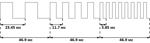
The figure below shows the operation of the Sweep unit with NRX0 = 0x61:
Frequency changes continuously until one of the limits for the frequency value is reached or someone disables the Sweep unit. If the frequency reduction mode is turned on and the next frequency turns out to be negative, then the previous value is saved and the calculations stop. If the frequency increase mode is on, and it has exceeded the maximum value (2047), the channel stops, and a zero is written in the corresponding status bit of register NR52, which indicates that the channel is stopped.
This ends simple things and begins unobvious details. Sweep contains several hidden registers that are not accessible from the outside - the flag of activity (internal enabled flag) and the buffer register for the frequency (frequency shadow register). It also contains a counter to comply with the period set in the NRX0 register.
I have already mentioned that the restart bit in the NRX4 register, also called trigger, is relevant for the modulation components. When installed in the Sweep Unit, the following occurs:
- The channel frequency (NRX3 and NRX4) is copied to the frequency register buffer.
- The counter is reset. To do this, from register NRX0 you need to copy bits 6-4, i.e. the counter will show the number of samples at a frequency of 128 Hz. Frame Sequencer will generate samples at this frequency, therefore, the counter must correspond to it. As you can see, there are no unnecessary transformations if everything is done correctly.
- The activity flag is set if the period or step is not equal to zero. Otherwise, it is reset.
- If the step is not equal to zero, then the new frequency is calculated and checked for overflow (no more than 2047), but the new frequency is not saved - everything is done just for the sake of checking for overflow.
And so, what happens when the counter says it’s time to update the frequency. First we reset the counter. Then we check the activity flag - if it is set, then the new frequency is calculated according to the formula above, with the difference that the frequency register-buffer acts as F (t - 1). There is an overflow check right there - if the new frequency exceeds 2047, then the channel is turned off.
If there was no overflow and the step is not equal to zero, then the new frequency value is written to the NRX3 and NRX4 registers, as well as to the frequency buffer register. Immediately another calculation of the new frequency occurs and the overflow check, but this frequency is not saved - this is all done only for the sake of another overflow check.
The frequency register buffer cannot be omitted here. Its presence leads to the fact that full manual control of the channel frequency during Sweep unit operation is impossible. We can change the frequency ourselves, but it will be so until the Sweep unit is counted - since it uses the frequency register-buffer in the calculations, our frequency value will be ignored and overwritten, and the calculations will continue, as if nothing it happened.
Now there are two oddities that the modulation components in DMG abound:
- As mentioned earlier, a period with a value of 0 means that the Sweep unit is disabled. This is logical and should have been just like that, but in reality for a DMG, a period with a value of 0 in the NRX0 register means that the period is 8. No frequency calculations take place, just the Sweep unit is idle. Test ROMs verify this.
- Imagine such a scenario. The game has set the frequency reduction mode. Some time passed and a new frequency was calculated. If after this the game tries to set the frequency increase mode, the channel will be immediately disabled. Thus, if in the mode of decreasing the frequency at least one calculation of the new frequency has occurred, then changing the mode to increase the frequency disables the channel.
Length counter
This component is the simplest counter. It measures a certain number of samples, and then disconnects the audio channel connected to it. This component is present on all channels and uses the NRX1 register for its work - it stores the duration of the channel playback. I will not give its structure - all channels have a different number of bits for the duration value. In addition, for Length Counter, the value is bit 6 in the NRX4 register, which turns this component on / off.Frame Sequencer generates samples for this component at a frequency of 256 Hz. The values in the register NRX1 are indicated in samples at such a frequency that, once again, means freedom from conversion. At each countdown, the changes are written back to the register - register NRX1 and is a counter.
Before using the duration value from the NRX1 register, it must be converted according to the following formula:
Counter = (~ NRX1 & Mask) + 1,
where Counter is the counter, Mask is the mask with which only the duration value is extracted from the register (it sometimes still contains the coefficient filling). This will give us the number of samples at a frequency of 256 Hz.
Everything seems to be extremely obvious - an elementary counter. At the next count, we check the flag in the NRX4 register for truth and, if successful, mark the count in the component counter. If the counter reaches the end value, the channel is disabled. Difficulties arise in the implementation of the next oddities - they are all concentrated in the NRX4 register change handler:
- If the component was turned off and is now turned on using bit 6, the counter has not reached zero, and the current state of the Frame Sequencer counts our component (all even states), then we immediately count. This can lead to the counter reaching zero and the channel being disconnected, but here one more condition must be taken into account - the channel is disconnected here only if the channel is not restarted, i.e. The restart bit is zero.
- If a restart is performed and the counter reaches zero, then the maximum possible duration value is written to the NRX1 register, i.e. all bits of duration are nullified (see the formula above). If at the same time the component is switched on (the previous value is not important) and the current state of the Frame Sequencer counts our component, then we immediately count down. There are no conditions here anymore - the channel has disconnected, which means it has disconnected.
Envelope unit
This component controls the sound volume by decreasing or increasing it with a constant step with a certain period. Volume in this case means the amplitude of the generated signal. This component is monitored through the NRX2 register:| Bits | Appointment |
| 7-4 | The initial value of the amplitude |
| 3 | Mode: 0 - decrease 1 - increase |
| 2-0 | Period |
Frame Sequencer generates samples for this component at a frequency of 64 Hz. The values in the NRX2 register are indicated in samples at that frequency. At each countdown, the internal period counter is counted. When he counts one period, the value of the amplitude increases / decreases by one. When the limit values are reached, the calculations stop. At an amplitude of 0, obviously, the channel is muffled, but active.
The figure above shows a graph of the amplitude of the signal during the operation of the Envelope unit with an NRX2 value of 0x55. The initial value of the amplitude is set when the channel is restarted (trigger) - in this case it is 5. In the process, it is no longer used and is not modified. Then, with each period, the amplitude decreases by one until it reaches zero.
Now another oddity. First, when modifying the NRX4:
- As for the Sweep unit, period 0 means that the period is 8. Again, no calculations occur - the component is idle.
- If the channel restarts and the next state of the Frame Sequencer generates a count for Envelope, then the period counter is set to one more than it should be.
- If the channel restarts, the initial amplitude value is zero and the amplitude reduction mode is set, the channel is immediately turned off.
Now when modifying NRX2:
- If the current (new value has not yet been recorded) NRX2 value contains a period equal to zero, and the period counter has not finished counting (we remember that period 0 means 8), then the current amplitude value must be increased by one. Otherwise, we check the current mode - if this is a decrease, then the amplitude should be increased by 2. That is, all this will lead to an immediate increase in the amplitude of the signal generated by the channel.
- If the mode changes, the amplitude is set equal to 16 minus the amplitude value.
- After all operations, the amplitude value is cut to the lower 4 bits.
The Envelope unit has the strangest behavior of all, but, unfortunately, only the mentioned oddities are documented. The behavior on real DMG is much more complicated, but no emulator can boast of its accurate implementation.
Sound Channel 3
This sound channel generates a wave according to the contents of the Wave Pattern RAM, which is located in the I / O ports memory area. Wave Pattern RAM is 16 bytes long and contains 32 samples. Each byte contains 2 samples - the first sample in the upper 4 bits, the second in the lower 4 bits. The contents of the memory are played cyclically with the frequency set in the registers NR33 and NR34 (the structure of these registers is identical to 1 and 2 channels).This channel contains only the Length Counter of the modulation components - its operation is identical to the rest of the channels and is controlled using register NR31. The signal amplitude is manually adjusted. The amplitude value is set using the NR32 register, which uses only 6 and 5 bits. They can have the following meanings:
- 00: The channel is muted but active.
- 01: Wave Pattern RAM plays as is.
- 10: Wave Pattern RAM is played back with a preliminary shift of each sample 1 bit to the right.
- 11: Wave Pattern RAM is played back with a preliminary shift of each sample 2 bits to the right.
In addition, the NR30 register in bit 7 contains a flag that allows the reproduction of sound (other bits are not used). If it is 0, then it is prohibited. Otherwise, it is allowed. It is important to understand that this flag does not have a one-to-one correspondence with the status bit in register NR52 for this channel. If bit 7 in NR30 is set, then sound can be reproduced - the status bit for this channel in NR52 can remain zero, and sound will not be output. Playback is allowed but not started. If the flag is cleared, this also leads to the channel being disabled, which leads to the reset of the status bit in NR52.
The timer in Wave generator works with a period of 2 * (2048 - X), where X is the frequency from the NRX3 and NRX4 registers. In this case, the frequency does not mean the frequency of the sound, but the frequency at which the next sample is read from Wave Pattern RAM.
Channel 3, among other things, contains a pointer to the current sample and a sample buffer - their presence in the emulator is necessary for accurate emulation. At the next timer count, the pointer moves to a new position, and the current byte is copied to the sample buffer (it is obvious that the byte will be the same for every two samples). Next, another oddity comes into play:
- When the channel is restarted, the pointer is reset, but the first byte from the Wave Pattern RAM is not copied to the sample buffer - this will happen only at the next timer countdown. This means that the first sample from the sample buffer that still contains the old byte will be played first; at the next timer count, the first byte from Wave Pattern RAM will be copied to the buffer, the pointer will be moved to the second sample, which means that the second sample from Wave Pattern RAM will be played. Further, everything will continue as it should. As a result, upon restarting, the first sample will not be played until the entire Wave Pattern RAM is played at least once.
- If channel 3 is working, then the game has access to Wave Pattern RAM only if at the same moment channel 3 reads from it. Otherwise, read operations return 0xFF, and write operations are ignored. If channel 3 is working and reading or writing occurs at the moment when channel 3 reads a sample, then operations occur only on the byte pointed to by the pointer of the current sample - it does not matter where the reading or writing comes from. Read and write operations work normally only with channel 3 disabled - then you can read and write Wave Pattern RAM anywhere.
- Restarting channel 3 while reading a sample will damage the first four bytes in Wave Pattern RAM. If the pointer of the current sample is within the first four bytes, then the first byte of Wave Pattern RAM will be overwritten by the contents of the sample buffer. If the pointer of the current sample is in a different position, then all 4 first bytes will be overwritten with the contents of that four bytes (4-7, 8-11, 12-15) where the pointer is located. For example, if the pointer is 10 bytes, then the contents of the first four bytes will be overwritten with bytes 8-11.
With the first paragraph, everything is elementary. The rest is not so easy to implement, especially when there is no mention of the subtleties of implementation on the Internet. Their implementation in CookieBoy is the result of almost random attempts to manipulate a timer counter that moves the pointer of the current sample. Here is what I managed to unearth.
So. The key to implementing the last two points is to understand what happens when the channel is restarted (trigger) through register NR34. Obviously, we need to reset the timer counter and the current sample pointer. Reset the sample pointer according to the first paragraph above - everything is simple here. With the counter, everything is not so simple, here lies the key to solving the problem.
Resetting the counter when the channel is restarted is an obvious and incorrect solution. In fact, the counter is initialized in such a way that there is a delay before the update of the position of the current sample begins. The delay is equal to the period of the timer (I have already given the formula) plus a certain constant (most likely no more than 8 measures), which you have to choose for yourself. Those. instead of counting one period and updating the position of the pointer, the timer counts two periods plus a certain constant. After that, the timer operates as usual, counting down the set one period.
This is how it works in my emulator. The ClockCounter variable is a tick counter. She has an iconic type. As soon as it reaches a value equal to the period of the timer, I update the position of the pointer of the current sample and reset the counter (subtract the value of the period from it). When restarting the channel using NR34, I set ClockCounter = -Period - 3, where Period is the value of the timer period in ticks according to the formula given above, 3 is the same magic constant. This gives the necessary delay and allows you to find out at what point in time you can read / write Wave Pattern RAM. If the ClockCounter variable is 3 at the time of reading or writing to Wave Pattern RAM, then these operations are available. Otherwise, return 0xFF.
Now the sample pointer. When I restart, I write to it 1. It is this combination of delay and the value of the sample pointer when restarting that allows me to pass test ROMs. Do not forget only about the fact that the second sample played after restarting is the second sample in Wave Pattern RAM. Due to the delay, the old contents of the sample buffer will be played twice (see the first oddity), and then the third sample from Wave Pattern RAM. This is the peculiarity of my implementation, therefore, as soon as the timer after the channel has restarted passes the entire delay (becomes non-negative), I update the contents of the sample buffer.
With the damage of the first four samples, everything is elementary, only now the ClockCounter must be equal to 1 so that the damage and overwriting of the first bytes of Wave Pattern RAM occur.
Do not forget that restarting the channel is not just an entry in NR34. All of the above and the restart itself occurs only when 1 is written to the high bit of NR34 and register NR30 allows playback (high bit is set).
Sound Channel 4
This channel generates noise. The Length counter and Envelope unit are connected to it - their behavior is no different from that in other channels. The same registers are reserved for them - NR41 and NR42, respectively. This channel does not contain frequency in the usual sense - NR43 is used for completely different purposes, and NR44 contains all the usual flags, but the bits for the frequency are not used.The noise generator is based on the so-called LFSR - Linear Feedback Shift Register or shift register with linear feedback. This is a pseudo random bit sequence generator. The principle of its work is quite simple.
The shift register is a repository for a bit sequence of a certain length (in a DMG, the shift register can be 7 or 15 bits long). Certain bits of the shift register are marked as taps - it is thanks to them that a sequence is generated. In DMG, taps are the 0 and 1 bits of the shift register. For continuous operation of the LFSR, a clock generator is used that generates samples to calculate the next bit of the pseudo-random sequence.
At the beginning, the shift register is initialized with any non-zero bit sequence - if all the bits are equal to zero, then at the output of LFSR we will always get zero. At the next countdown, the following occurs:
- The taps are summed modulo 2 (operation XOR), and the result is saved for further operations.
- The rightmost bit (bit 0) of the shift register is taken as the next value of the generated sequence.
- The shift register is shifted to the right by one bit.
- The freed leftmost bit records the result of the sum of taps modulo 2, which we saved in the first step.
The output is a pseudo-random bit sequence. It is pseudo-random for the reason that it has a period - from a certain moment the whole sequence is looped. The period length (T) is calculated by the following formula:
T = 2 N - 1,
where N is the length of the shift register in bits. The period is determined by the maximum number of different states of the shift register except one, when all bits are equal to zero. Thus, for a 7-bit register, the period will be 127, and for a 15-bit register it will be 32767. This leads us to the question - calculate everything honestly or use pre-generated sequences. The result will be identical, as the LFSR is guaranteed to loop. I used the second approach. Sequences can be found in the LFSR7.inc and LFSR15.inc files.
To control the LFSR register NR43 is used. Here is its structure:
| Bits | Appointment |
| 7-4 | Timer frequency shift: 0000: 1/2 0001: 1/2 2 0002: 1/2 3 0003: 1/2 4 ... 1101: 1/2 14 1110: not used 1111: not used |
| 3 | Shift Register Length: 0: 15 bit 1: 7 bit |
| 2-0 | Frequency Multiplier: 000: 2 001: 1 010: 1/2 011: 1/3 100: 1/4 101: 1/5 110: 1/6 111: 1/7 |
With the length of the shift register, everything is clear. The remaining bits are used to calculate the frequency of the LFSR clock. It is calculated (F) according to the following formula:
F = f * Shift * Ratio,
where f = 4194304 Hz, Shift - frequency shift of the timer (values are shown in the table above), Ratio - frequency multiplier (values are shown in the table above). If the frequency shift bits are 1110 or 1111, then the LFSR does not receive samples, which means channel 4 is muted.
Implementation
To implement the sound, I chose SDL. This library has an extremely simple API for generating procedural sound — we specify the sound parameters, the length of the sample buffer, the callback function, and all. SDL automatically calls this function, where we “feed” it the next batch of samples. After playing them back, the function is called again, etc. Besides the simple API, another advantage of SDL is its good work with extremely small sample buffers, and latency is very important for us.I will not go into the details of the implementation of the components of the sound system. The theoretical part contains everything you need. Just touch on the synchronization problem.
The problem is that now we need to support not only the screen refresh rate, but also the rate of sample generation. SDL calls a callback function at equal (although I did not see any guarantees in the documentation) time intervals and “expects” that we will record a new portion of samples. If these samples are not available at the right time, then we get an intermittent sound. At the same time, it may turn out that the emulation rate is too high and the next portion of samples will need to be saved somewhere for playback later.
A ring buffer is best suited for storing samples. The emulator writes portions of samples to it, and the callback function takes them if necessary. The ring buffer solves several problems at once:
- нам не надо следить за границами массива – данная структура данных все сделает за нас. Бонусом является еще и то, что кольцевой буфер имеет фиксированный размер;
- хранение порций сэмплов в правильном порядке;
- упрощение реализации ускоренной эмуляции. Дело в том, что при отсутствии достаточного количества свободного места кольцевой буфер перезаписывает уже имеющиеся данные. При ускоренной эмуляции порции сэмплов будут поступать быстрее, чем мы сможем их воспроизвести. Поскольку мы никого не ждем и пишем поверх старого, то темп звука будет соответствовать темпу эмуляции;
- поддержание темпа эмуляции. Это несколько противоречит предыдущему пункту, но дело вот в чем. Если поступила очередная порция сэмплов, а в кольцевом буфере нет для нее места, то вместо перезаписи мы ждем, пока callback-функция не заберет из буфера порцию сэмплов. Только после этого мы добавляет очередные сэмплы в буфер и продолжаем эмуляцию.
The last point gives an interesting side effect - we can completely abandon the manual maintenance of the emulation rate (60 Hz). The necessary delays in emulation will be ensured by waiting for the callback function to be called. There are conditional variables (SDL_cond) in the SDL for this. With the help of them, the stream goes into standby mode and waits for a signal from another stream that it is possible to continue working. For us, the waiting thread is an emulation thread - it waits for another thread (callback function) to take samples from the ring buffer and thereby free up space for the next batch. When we need the maximum possible speed of emulation, we do not wait for anyone and write to the ring buffer. Naturally do not forget about mutexes.
Everything works so well for one simple reason - the generation of samples occurs at the same rate as the DMG processor.
Testing
As with other components, there are also test ROMs for sound. There is only one trick - for DMG and Gameboy Color, the test suites are different and it’s worth running them all. DMG tests should be passed without errors, but the tests for Gameboy Color, the real DMG passes with errors and displays the following:If, when you run all the tests, their execution does not stop immediately, but goes in cycles, then there is nothing to worry about. This is exactly the case when ROM tries to install a ROM bank that does not exist. If you cut the bank number, as I do, then the tests go in cycles. The same thing is observed with Gambatte, but you can trust him.
I recommend that you immediately arm yourself with the source code of the tests and understand how they work. This will greatly speed up the process, and sometimes this is the only way to understand what you need to do. Although a description of the error is displayed on the screen, it is sometimes difficult to understand what exactly is required of you and which registers are involved.
And so, the simplest tests are 01-registers and 11-regs after power. The first tests how reading and writing sound registers occurs. I have already mentioned how it is worth considering the bits of registers that are unused and inaccessible to reading - this is exactly what the test checks. In addition, the results of operations are checked with the sound on / off. The second tests the behavior of the registers when turning off the sound. The source code says in more detail what exactly is being tested.
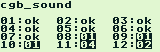
“02-len ctr” tests the behavior of the Length counter in the boundary conditions. Testing takes place for each channel separately, in the process the number of the tested channel is displayed.
“03-trigger” is another test for the Length counter, but now its behavior is checked when modifying the NRX4 register. Basically, it is here that all the mentioned oddities of the Length counter are tested.
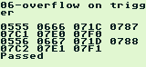
“04-sweep”, “05-sweep details” and “06-overflow on trigger” test the Sweep unit. In addition to normal operation, all the mentioned component oddities are tested here. To pass the “06-overflow on trigger” test, the following should be displayed on the screen:
“07-len sweep period sync” checks if the Sweep unit and Length counter are synchronized correctly. If the Frame Sequencer is implemented correctly, then there should be no problems with this test.
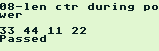
"08-len ctr during power" tests the behavior of the Length counter when turning off the sound. To pass the test during it, the following should be displayed on the screen:
“09-wave read while on” is testing the read operations while channel 3 is running. To pass the test, the following should be displayed
on the screen : The value from Wave Pattern RAM and FF is displayed every other time. due to a ban on reading. They alternate (00 FF, 11 FF, etc.), but at the beginning the read operation does not pass twice and FF FF is output. This is the most difficult thing to achieve, and it required me to sort through different values of the constant and counter (determining the moment when the read operation is allowed).
“10-wave trigger while on” tests damage to the first bytes of Wave Pattern RAM when channel 3 restarts while reading a sample. A lot of information is displayed on the screen, and it does not fit completely. Here is the result of the test passed:
Even from this piece you can see where the damage to the Wave Pattern RAM should occur.
“12-wave write while on” tests the write operations in Wave Pattern RAM during the operation of channel 3. Here too much information is displayed, here is the result of the passed test:
It is clear where and what to look for - the test tries to write the value 0xF7.
It is worth saying that passing these tests personally did not give me anything in the games I tested. And without passing them, the sound was normal, and judging by other emulators with enviable compatibility that fail all sound tests, this is not necessary at all. Although it’s nice to realize that the emulator works like real hardware. If a game that depends on the subtleties of iron comes across, then it will work correctly.
What's next
At the moment, our emulator supports all the mandatory and not quite DMG functions. Naturally, there is room for development, namely:- Support for serial port or Game link.
- Support for less common MBC-controllers - Pocket Camera, Bandai TAMA5, Hudson HUC-3, Hudson HUC-1, cartridges with vibration.
In the end, there is one feature of DMG that none of the well-known emulators support, even the most accurate ones like Gambatte. This is an iron bug that causes garbage to be written to the OAM memory area. This feature is almost never documented and quite insidious in implementation.
A bug occurs when certain processor instructions are executed with certain operand values. This is the easy part. It is more difficult to emulate the fact that garbage is recorded not by accident and has a certain content. It is even more difficult to emulate that this bug occurs only at certain intervals of the LCD controller. It was for these details that I did not find any documentation - there are only test ROMs that do not help much. With them you can implement this bug only partially.
There is a minimum of sense in implementing this bug - it is unlikely that some developer deliberately used it or left it in the game release. The same sound bugs due to Wave Pattern RAM are found in games, and they have practical meaning.
Conclusion
At this point, the series of articles came to an end. As I said, the result is an emulator with good compatibility and support for all the most important functions. This is not a shame to put next to other implementations. And thanks to the use of test ROMs for implementation and testing, we can talk about high accuracy of iron emulation, rather than simple compatibility with games.Naturally, the emulator has a lot to develop. In addition to the above, there is another logical direction for the development of the emulator - Gameboy Color (СGB) emulation. DMG and CGB are not just consoles of the same family - they are almost identical internally. Literally several modules need to be added to the existing emulator.
At the moment, Cookieboy does not emulate CGB, but I plan to do this in the near future. This will also be an article.
If someone decides to implement their emulator or if something is not clear in the articles themselves, then you can contact me with questions, I will be happy to help. In the comments to the articles or in Habrahpost - it does not matter.