September 11, 2012 at 16:30
Minor repairs and calibration of the APC SmartUPS 700
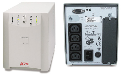
This article has been visited by some aspects of the operation and self-repair of the APC SmartUPS 700 and similar UPSs.
All this information is provided “as is” for review and for its practical application neither I nor APC Corporation are responsible. At your peril. There are 220 volts, I warned you.
Background.
This representative of uninterruptible power supply lived with me for many years in good health, until something heavy was dropped on the lid in the center, after which the patient completely “fell off his brain” and did not become unconscious.
(it should be noted that there was no longer a protective film on top of the board, it was lost in service centers)
An autopsy revealed several burns in the area where the grounded cover and the board came in contact with and traces of old (not mine) repairs. Since there was an opportunity, the UPS was put into service, where they brought him to his senses, and he worked for another half a year, after which he began to behave inappropriately. It was decided to connect it to the computer and check the response thresholds, battery charge, etc., well, that’s why it’s “smart”, which can show a lot of things.
We are connected.
And here the problems began, none of the lanyard schemes for connecting it to the computer worked, nor did any existing cord. All programs said that the UPS was not connected, and the only thing that was visible in the terminal was the “?” Sign that appeared when it was turned on, which indicated that the mains voltage suddenly disappeared. After a long study of the manuals, the following data was found:
For communication via the Smart protocol, the cord 940-0024C is needed, here it is and its wiring.
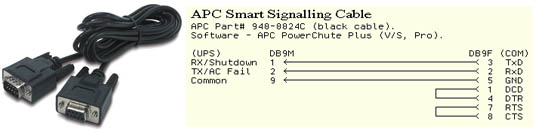
But, as already mentioned, the connection according to this scheme did not bring any success. After further digging into the world trash, the Smart UPS 700 circuit was excavated, or rather the 640-0730P version board, although I had the 640-0730N version, the differences were not fundamental. It was found that the DB9F connector on the rear panel of the UPS receives signals through a specialized IC2 chip (according to the scheme), obviously, among other things, it performs decoupling and matching of TTL UART with RS232 levels.
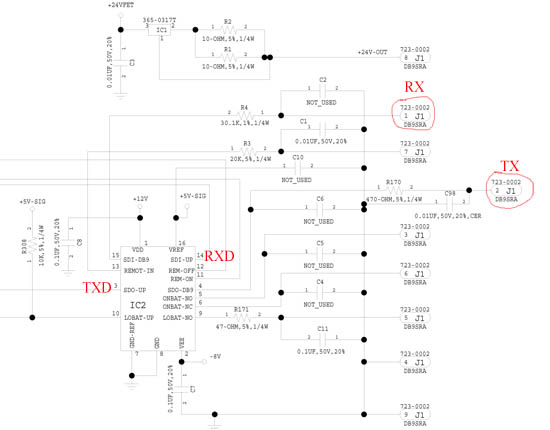
The RX (1 DB9) and TX (2 DB9) connection lines of interest to us are connected, respectively, to pins 15 (SDI) and 4 (SDO) of this chip. Checking the resistors and capacitors in these lines yielded nothing, from which it was suggested that the SDI IC2 input would burn out. Since there was nothing to replace the microcircuit, it was decided to try to connect to the UPS bypassing it. This UPS model uses the P83C654 microcontroller. A quick read of the datasheet on it showed that communication with the outside world occurs through the standard Full Duplex UART, with TTL levels of 5V, and they come to the outputs SDO-UP (3 IC2) (TXD) and SDI-UP (14 IC2) (RXD) deceased IC2 microcircuit.
Further, a matter of technology. A telephone cord was purchased at the nearest mobile phone store, but in fact a USB-UART adapter on the PL2303 controller, the telephone connector was removed, only the RXD, TXD, GND lines were left.
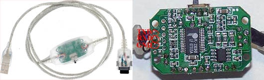
We connect the lace with pins 3 (TXD), 14 (RXD), 8 (GND), we connect at 2400 baud, data is 8 bit, 1 stop bit, without parity, and cheers! Everything works.
According to the SMART protocol, of course, the rest of the IC2 lines are not used.
Calibration
Now about why it all began. On occasion, I had 2 new 12V 7.2A / H batteries, after installing them, turning them on and checking under a load of 2x100 Watt bulbs, the results were not encouraging - the UPS worked for a couple of minutes and turned off when the battery was fully charged ... Well, it’s clear that something it's not like that. Performing a calibration with the “D” command in Smart mode yielded nothing. Smoke mana again.
The microcontroller stores all the dynamic characteristics of the battery in register 0 of non-volatile memory, and when the battery ages, the decreasing coefficient value for calculating the capacity is entered in this register.
So, UPS itself does not know how to increase the value of this register when performing calibration! You need to write the default value there - 0x96 (in hexadecimal) (for Smart UPS 700) manually, through the terminal, before calibration, and then, after starting the calibration with a load of 30-40%, be patient and wait ...
PS. A couple of links that helped in resolving the issue. SmartUPS protocol, description of registers, schemes, everything that did not fit here.
masterjoy.narod.ru/UPS/ups.html
www.saprjkin.narod.ru/UPS_SMART.htm