Reverse "Neuromant". Part 3: Finished Rendering, Making the Game

Hi, this is the third part of my series of publications devoted to the reverse development of Neuromant, the video game incarnation of the novel of the same name by William Gibson.
Reverse "Neuromant". Part 1: Sprites
Reverse "Neuromant". Part 2: Render the Font
This part may seem a bit messy. The fact is that most of what was told here was ready while the previous one was being written . Since two months have already passed since then, and unfortunately I have no habit of keeping working notes, I simply forgot some details. But as it is, let's go.
[After I learned to print lines, it would be logical to continue reversing the construction of dialog boxes. But, for some reason escapes me, but instead I went to the entire analysis of the rendering system]. Once again, walking along the mainy, managed to localize the call, the first outputting anything to the screen seg000:0159: call sub_1D0B2. “Something”, in this case, is the cursor and the background image of the main menu:
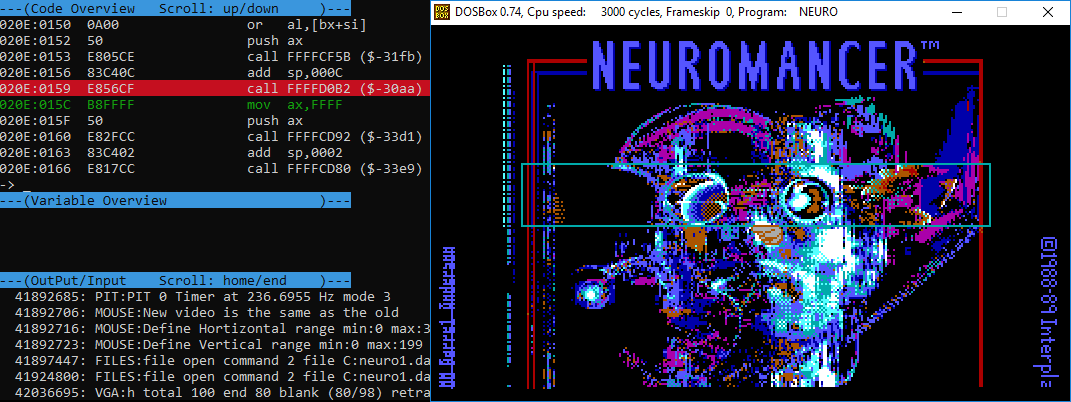
It is noteworthy that the function sub_1D0B2[hereinafter - render] has no arguments, however, its first call was preceded by two, almost identical pieces of code:
loc_100E5:                      loc_10123:
    mov     ax, 2                   mov     ax, 2
    mov     dx, seg seg009          mov     dx, seg seg010push    dx                      push    dx
    push    ax                      push    ax
    mov     ax, 506Ah               mov     ax, 5076h   ; "cursors.imh", "title.imh"push    ax                      push    ax
    call    load_imh                call    load_imh    ; load_imh(res, offt, seg)
    add     sp, 6                   add     sp, 6subax, axsubax, 0Ahpushaxpushaxcallsub_123F8callsub_123F8; sub_123F8(0), sub_123F8(10)
    add     sp, 2                   add     sp, 2
    cmp     word_5AA92, 0           mov     ax, 1
    jz      short loc_10123         push    ax
    subax, axmovax, 2
    pushaxmovdx, segseg010movax, 2                   pushdxmovdx, segseg009pushaxpushdxsubax, axpushaxpushaxmovax, 64hpushaxpushaxmovax 0Ahmovax, 0A0hpushaxpushaxcallsub_1CF5B; sub_1CF5B(10, 0, 0, 2, seg010, 1)
    subax, axaddsp, 0Chpushaxcallrendercallsub_1CF5B; sub_1CF5B(0, 160, 100, 2, seg009, 0)
    add     sp, 0Ch
Before the call render, the cursors ( cursors.imh) and background ( title.imh) are unpacked into memory ( load_imh- this is renamed sub_126CBfrom the first part ), into the ninth and tenth segment, respectively. A superficial study of the function sub_123F8did not bring me any new information, but then, just looking at the arguments sub_1CF5B, I made the following conclusions:
- arguments 4 and 5, taken together, represent the address of the unpacked sprite (
segment:offset); - arguments 2 and 3 are probably coordinates, since these numbers correlate with the image displayed after the call
render; - The last argument can be the flag of the opacity of the sprite background, because the unpacked sprites have a black background, and we can see the cursor on the screen without it.
With the first argument [as well as with the rendering as a whole] everything became clear after tracing sub_1CF5B. The fact is that in the data segment, starting from the address 0x3BD4, there is an array of 11 structures of the following type:
typedefstructsprite_layer_t {uint8_t flags;
    uint8_t update;
    uint16_t left;
    uint16_t top;
    uint16_t dleft;
    uint16_t dtop;
    imh_hdr_t sprite_hdr;
    uint16_t sprite_segment;
    uint16_t sprite_pixels;
    imh_hdr_t _sprite_hdr;
    uint16_t _sprite_segment;
    uint16_t _sprite_pixels;
} sprite_layer_t;
I call this concept "sprite chain". In effect, the function sub_1CF5B(hereinafter - add_sprite_to_chain) adds the selected sprite to the chain. On a 16-bit machine, it would have something like the following signature:
sprite_layer_t g_sprite_chain[11];
voidadd_sprite_to_chain(int index,
    uint16_t left, uint16_t top,
    uint16_t offset, uint16_t segment,
    uint8_t opaque);
It works like this:
- the first argument is the index in the array
g_sprite_chain; - arguments
leftand aretopwritten in the fieldg_sprite_chain[index].leftand,g_sprite_chain[index].toprespectively; - The sprite header (the first 8 bytes located at the address
segment:offset) is copied into a fieldg_sprite_chain[index].sprite_hdr, of the typeimh_hdr_t(renamedrle_hdr_tfrom the first part):
typedefstructimh_hdr_t {uint32_t unknown;
    uint16_t width;
    uint16_t height;
} imh_hdr_t;g_sprite_chain[index].sprite_segmentvalue is recorded in the fieldsegment;- the field is
g_sprite_chain[index].sprite_pixelswritten a value equaloffset + 8, thussprite_segment:sprite_pixels- this is the address of the bitmap sprite being added; - field
sprite_hdr,sprite_segmentandsprite_pixelsduplicated_sprite_hdr,_sprite_segmentand_sprite_pixelsaccordingly [why? - I have no idea, and this is not the only case of such duplication of fields] ; - the field is
g_sprite_chain[index].flagswritten value equal to1 + (opaque << 4). This record means that the first bit of the valueflagsindicates the "activity" of the current "layer", and the fifth bit indicates the opacity of its background. [My doubts about the transparency flag were dispelled after I experimentally tested its effect on the displayed image. By changing the value of the fifth bit at runtime, we can observe these artifacts like this]: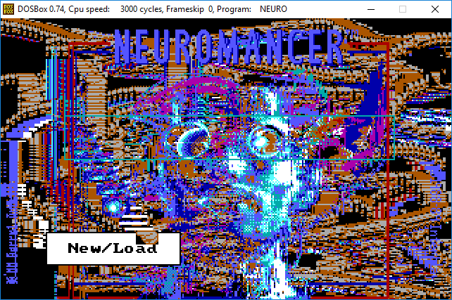
As I already mentioned, the function renderhas no arguments, but it doesn’t need it - it works directly with the array g_sprite_chain, transferring the “layers” to the VGA memory in turn, from the last ( g_sprite_chain[10]- background) to the first ( g_sprite_chain[0]- foreground). The structure sprite_layer_thas everything necessary for this and even more. I'm talking about the unexamined fields update, dleftand dtop.
In fact, the function renderredraws NOT ALL sprites in each frame. The fact that the current sprite needs to be redrawn indicates a non-zero field value g_sprite_chain.update. Suppose we move the cursor ( g_sprite_chain[0]), then something like this happens in the mouse movement handler:
voidmouse_move_handler(...){
    ...
    g_sprite_chain[0].update = 1;
    g_sprite_chain[0].dleft = mouse_x - g_sprite_chain[0].left;
    g_sprite_chain[0].dtop = mouse_y - g_sprite_chain[0].top;
}
When control passes to the function render, the latter, having reached the layer g_sprite_chain[0], will see that it needs to be updated. Then:
- the intersection of the area occupied by the sprite of the cursor before the update with all previous layers will be calculated and drawn;
- Sprite coordinates updated:
g_sprite_chain[0].update = 0;
g_sprite_chain[0].left += g_sprite_chain[0].dleft
g_sprite_chain[0].dleft = 0;
g_sprite_chain[0].top += g_sprite_chain[0].dtop
g_sprite_chain[0].dtop = 0;- Sprite will be drawn on the updated coordinates.
This minimizes the number of operations performed by the function render.
It was easy to implement this logic, although I simplified it quite strongly. Given the computational power of modern computers, we can afford to redraw all 11 sprites chains in each frame due to this abolished field g_sprite_chain.update, .dleft, .dtopand all the associated processing. Another simplification concerns the handling of the opacity flag. In the original code, for each transparent pixel in the sprite, an intersection with the first opaque pixel in the lower layers is searched. But I use 32-bit video mode, and therefore I can simply change the value of the transparency byte in the RGBA circuit. As a result, I have got such functions of adding (deleting) a sprite to (from) a chain (s):
typedefstructsprite_layer_t {uint8_t flags;
    uint16_t left;
    uint16_t top;
    imh_hdr_t sprite_hdr;
    uint8_t *sprite_pixels;
    imh_hdr_t _sprite_hdr;
    uint8_t *_sprite_pixels;
} sprite_layer_t;
sprite_layer_t g_sprite_chain[11];
voidadd_sprite_to_chain(int n, uint32_t left, uint32_t top,
            uint8_t *sprite, int opaque){
    assert(n <= 10);
    sprite_layer_t *layer = &g_sprite_chain[n];
    memset(layer, 0, sizeof(sprite_layer_t));
    layer->left = left;
    layer->top = top;
    memmove(&layer->sprite_hdr, sprite, sizeof(imh_hdr_t));
    layer->sprite_pixels = sprite + sizeof(imh_hdr_t);
    memmove(&layer->_sprite_hdr, &layer->sprite_hdr,
        sizeof(imh_hdr_t) + sizeof(uint8_t*));
    layer->flags = ((opaque << 4) & 16) | 1;
}
voidremove_sprite_from_chain(int n){
    assert(n <= 10);
    sprite_layer_t *layer = &g_sprite_chain[n];
    memset(layer, 0, sizeof(sprite_layer_t));
}
The function of transferring the layer to the VGA buffer is as follows:
voiddraw_to_vga(int left, int top,
    uint32_t w, uint32_t h, uint8_t *pixels, int bg_transparency);
voiddraw_sprite_to_vga(sprite_layer_t *sprite){
    int32_t top = sprite->top;
    int32_t left = sprite->left;
    uint32_t w = sprite->sprite_hdr.width * 2;
    uint32_t h = sprite->sprite_hdr.height;
    uint32_t bg_transparency = ((sprite->flags >> 4) == 0);
    uint8_t *pixels = sprite->sprite_pixels;
    draw_to_vga(left, top, w, h, pixels, bg_transparency);
}
A function draw_to_vgais a function of the same name described in the second part , but with an additional argument indicating the transparency of the background of the image. Add a call draw_sprite_to_vgato the beginning of the function render(the rest of its contents migrated from the second part ):
staticvoidrender(){
    for (int i = 10; i >= 0; i--)
    {
        if (!(g_sprite_chain[i].flags & 1))
        {
            continue;
        }
        draw_sprite_to_vga(&g_sprite_chain[i]);
    }
    ...
}
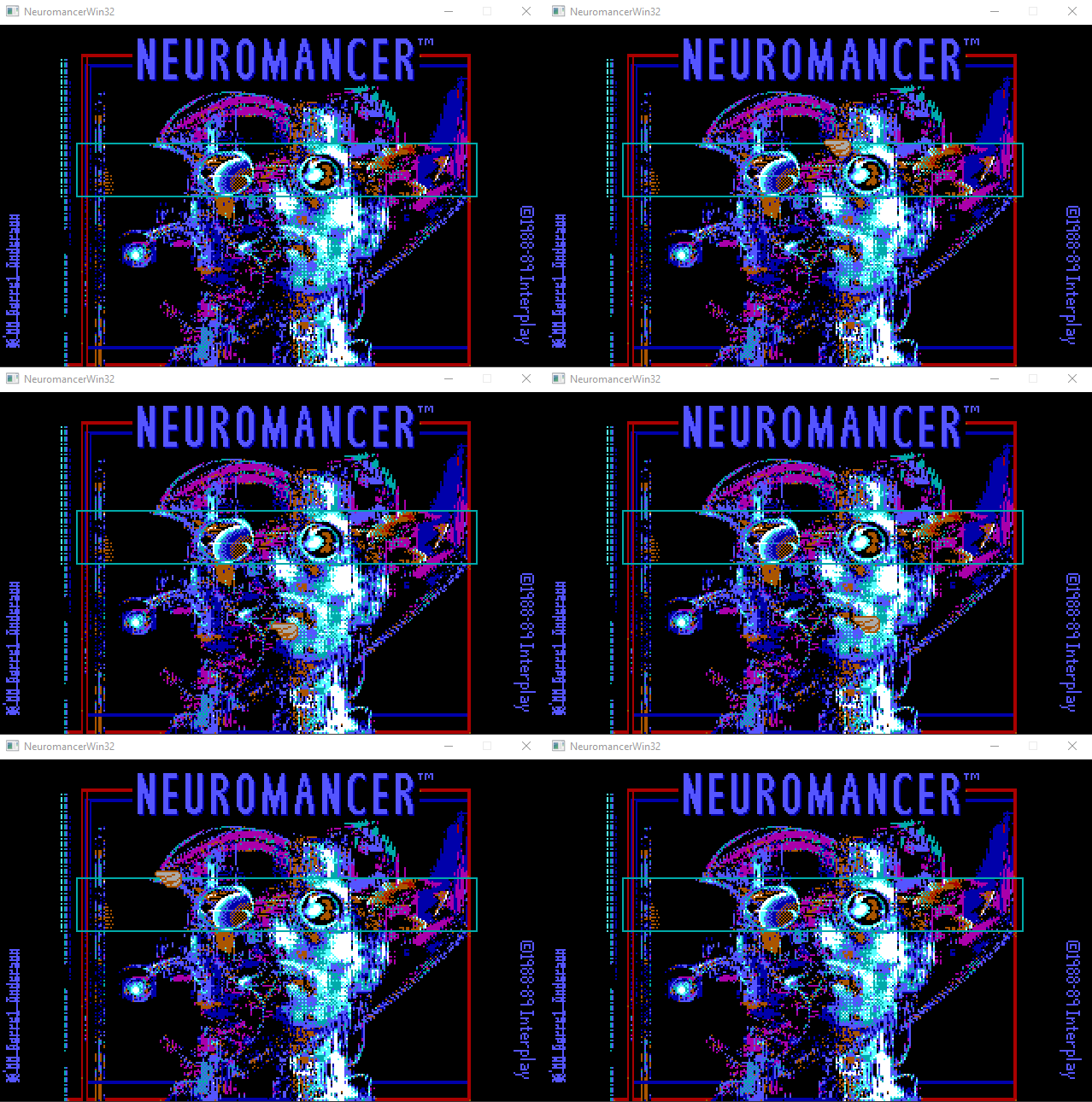
I also wrote a function that updates the position of the sprite cursor, depending on the current position of the mouse pointer ( update_cursor), and a simple resource manager. Making it all work together:
typedefenumspite_chain_index_t {
    SCI_CURSOR = 0,
    SCI_BACKGRND = 10,
    SCI_TOTAL = 11
} spite_chain_index_t;
uint8_t g_cursors[399];         /* seg009 */uint8_t g_background[32063];    /* seg010 */intmain(int argc, char *argv[]){
    ...
    assert(resource_manager_load("CURSORS.IMH", g_cursors));
    add_sprite_to_chain(SCI_CURSOR, 160, 100, g_cursors, 0);
    assert(resource_manager_load("TITLE.IMH", g_background));
    add_sprite_to_chain(SCI_BACKGRND, 0, 0, g_background, 1);
    while (sfRenderWindow_isOpen(g_window))
    {
        ...
        update_cursor();
        render();
    }
    ...
}
Okay, for the full main menu, the menu itself is actually not enough. It's time to return to the reversal of the dialog boxes. [Last time I disassembled the function draw_framethat forms the dialog box, and partly the function draw_string, taking only the text rendering logic from there.] Looking at the new one draw_frame, I saw that the function was used there add_sprite_to_chain— not surprising, just adding the dialog box to the sprite chain . It was necessary to deal with the positioning of the text inside the dialog box. Let me remind you what the function call looks like draw_string:
subax, axpushaxmovax, 1
    pushaxmovax, 5098h; "New/Load"push    ax
    call    draw_string     ; draw_string("New/Load", 1, 0)
and the structure that fills in draw_frame[here with a bit of advance, since most of the elements I named after I had completely figured out with draw_string. By the way, here, as in the case of ω sprite_layer_t, there is a duplication of fields] :
typedefstructneuro_dialog_t {uint16_t left;              // word[0x65FA]:   0x20uint16_t top;               // word[0x65FC]:   0x98uint16_t right;             // word[0x65FE]:   0x7Fuint16_t bottom;            // word[0x6600]:   0xAFuint16_t inner_left;        // word[0x6602]:   0x28uint16_t inner_top;         // word[0x6604]:   0xA0uint16_t inner_right;       // word[0x6604]:   0xA0uint16_t inner_bottom;      // word[0x6608]:   0xA7uint16_t _inner_left;       // word[0x660A]:   0x28uint16_t _inner_top;        // word[0x660C]:   0xA0uint16_t _inner_right;      // word[0x660E]:   0x77uint16_t _inner_bottom;     // word[0x6610]:   0xA7uint16_t flags;             // word[0x6612]:   0x06uint16_t unknown;           // word[0x6614]:   0x00uint8_t padding[192]        // ...uint16_t width;             // word[0x66D6]:   0x30uint16_t pixels_offset;     // word[0x66D8]:   0x02uint16_t pixels_segment;    // word[0x66DA]:   0x22FB
} neuro_dialog_t;
Instead of explaining what’s here, how and why, I’ll just leave this image:
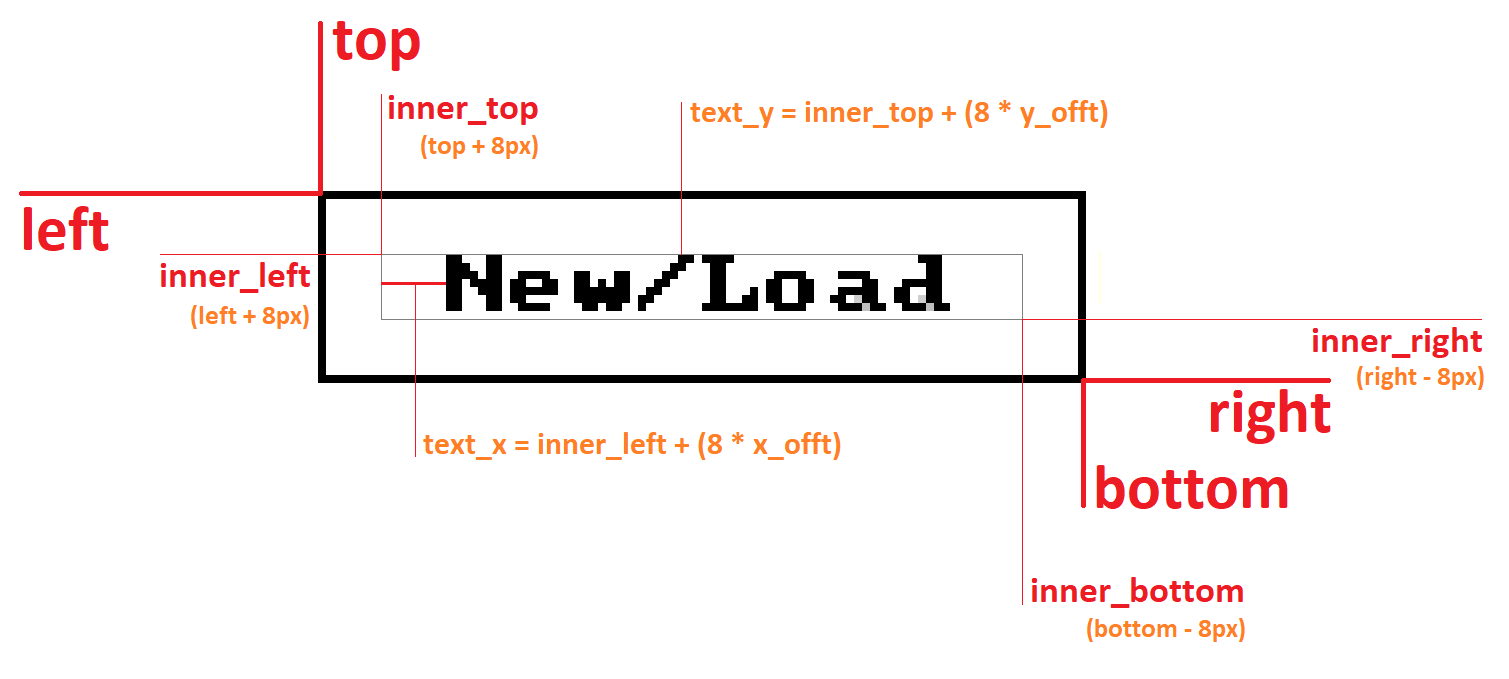
The variables x_offtand y_offtare the second and third function arguments, draw_stringrespectively. Based on this information, it was easy to build your own versions draw_frameand draw_text, after renaming them to build_dialog_frameand build_dialog_text:
voidbuild_dialog_frame(neuro_dialog_t *dialog,
            uint16_t left, uint16_t top, uint16_t w, uint16_t h,
            uint16_t flags, uint8_t *pixels);
voidbuild_dialog_text(neuro_dialog_t *dialog,
            char *text, uint16_t x_offt, uint16_t y_offt);
...
typedefenumspite_chain_index_t {
    SCI_CURSOR = 0,
    SCI_DIALOG = 2,
    ...
} spite_chain_index_t;
...
uint8_t *g_dialog = NULL;
neuro_dialog_t g_menu_dialog;
intmain(int argc, char *argv[]){
    ...
    assert(g_dialog = calloc(8192, 1));
    build_dialog_frame(&g_menu_dialog, 32, 152, 96, 24, 6, g_dialog);
    build_dialog_text(&g_menu_dialog, "New/Load", 8, 0);
    add_sprite_to_chain(SCI_DIALOG, 32, 152, g_dialog, 1);
    ...
}
The main difference between my versions and the original ones is that I use absolute pixel values - it's easier.
Already then, I was sure that the code section following the call immediately was responsible for creating the buttons build_dialog_text:
    ...
    mov     ax, 5098h           ; "New/Load"push    ax
    call    build_dialog_text   ; build_dialog_text("New/Load", 1, 0)
    add     sp, 6
    mov     ax, 6Eh             ; 'n' - этот
    push    ax
    subax, axpushaxmovax, 3
    pushaxsubax, axpushaxmovax, 1
    pushaxcallsub_181A3; sub_181A3(1, 0, 3, 0, 'n')
    add     sp, 0Ah
    mov     ax, 6Ch             ; 'l' - и этот комментарий сгенерировала Ида
    push    ax
    mov     ax, 1push    ax
    mov     ax, 4push    ax
    subax, axpushaxmovax, 5
    pushaxcallsub_181A3; sub_181A3(5, 0, 4, 1, 'l')
It's all about these generated comments - 'n'and 'l', which, obviously, are the first letters in the words "New"and "load". Further, if we argue by analogy with build_dialog_text, then the first four arguments sub_181A3(hereinafter - build_dialog_item) can be multipliers of coordinates and sizes [in fact, the first three arguments, the fourth, as it turned out, about the other] . Everything converges, if you impose these values on the image as follows:

Variables x_offt, y_offtand width, on the image, are, accordingly, the first three arguments of the function build_dialog_item. The height of this rectangle is always equal to the height of the symbol - eight. After a very close look at it build_dialog_item, I found out that what neuro_dialog_tI designated in the structure as padding(now - items) is an array of 16 structures of the following type:
typedefstructdialog_item_t {uint16_t left;
    uint16_t top;
    uint16_t right;
    uint16_t bottom;
    uint16_t unknown; /* index? */char letter;
} dialog_item_t;
And the field neuro_dialog_t.unknown(now - neuro_dialog_t.items_count) is the count of the number of items in the menu:
typedefstructneuro_dialog_t {
    ...
    uint16_t flags;
    uint16_t items_count;
    dialog_item_t items[16];
    ...
} neuro_dialog_t;
The field is dialog_item_t.unknowninitialized with the fourth function argument build_dialog_item. Perhaps this is the index of the element in the array, but, it seems, this is not always the case, and therefore - unknown. The field is dialog_item_t.letterinitialized by the fifth argument of the function build_dialog_item. Again, it is possible that in the handler of the click-click, the game checks that the coordinates of the mouse pointer hit the area of one of the items (just sorting them out in order, for example), and if there is a hit, then this field selects the desired handler for clicking on a specific button. [I don’t know how it was actually done, but at my place I implemented just such a logic.]
This is enough so that, no longer looking at the original code, but simply repeating its behavior observed in the game, make a full main menu.
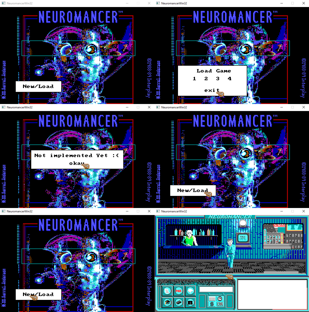
If you watched the previous GIF until the end, then you probably noticed the starting game screen in the last frames. In fact, I already have everything to draw it. Just take it and download the necessary sprites and add them to the sprite chain. However, placing the main character's sprite on the stage, I made one important discovery related to the structure imh_hdr_t.
In the original code, the function add_sprite_to_chainthat adds the image of the protagonist to the chain is called with the coordinates 156 and 110. This is what I saw by repeating it in my room:
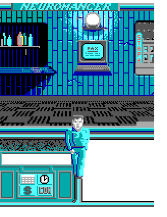
Having understood what was happening, I got the following type of structure imh_hdr_t:
typedefstructimh_hdr_t {uint16_t dx;
    uint16_t dy;
    uint16_t width;
    uint16_t height;
} imh_hdr_t;
What used to be a field unknownturned out to be offset values that are subtracted from the corresponding coordinates (during rendering) stored in the sprite chain.
Thus, the real coordinate of the upper left corner of the rendered sprite is calculated approximately as follows:
left = sprite_layer_t.left - sprite_layer_t.sprite_hdr.dx
top = sprite_layer_t.top - sprite_layer_t.sprite_hdr.dy
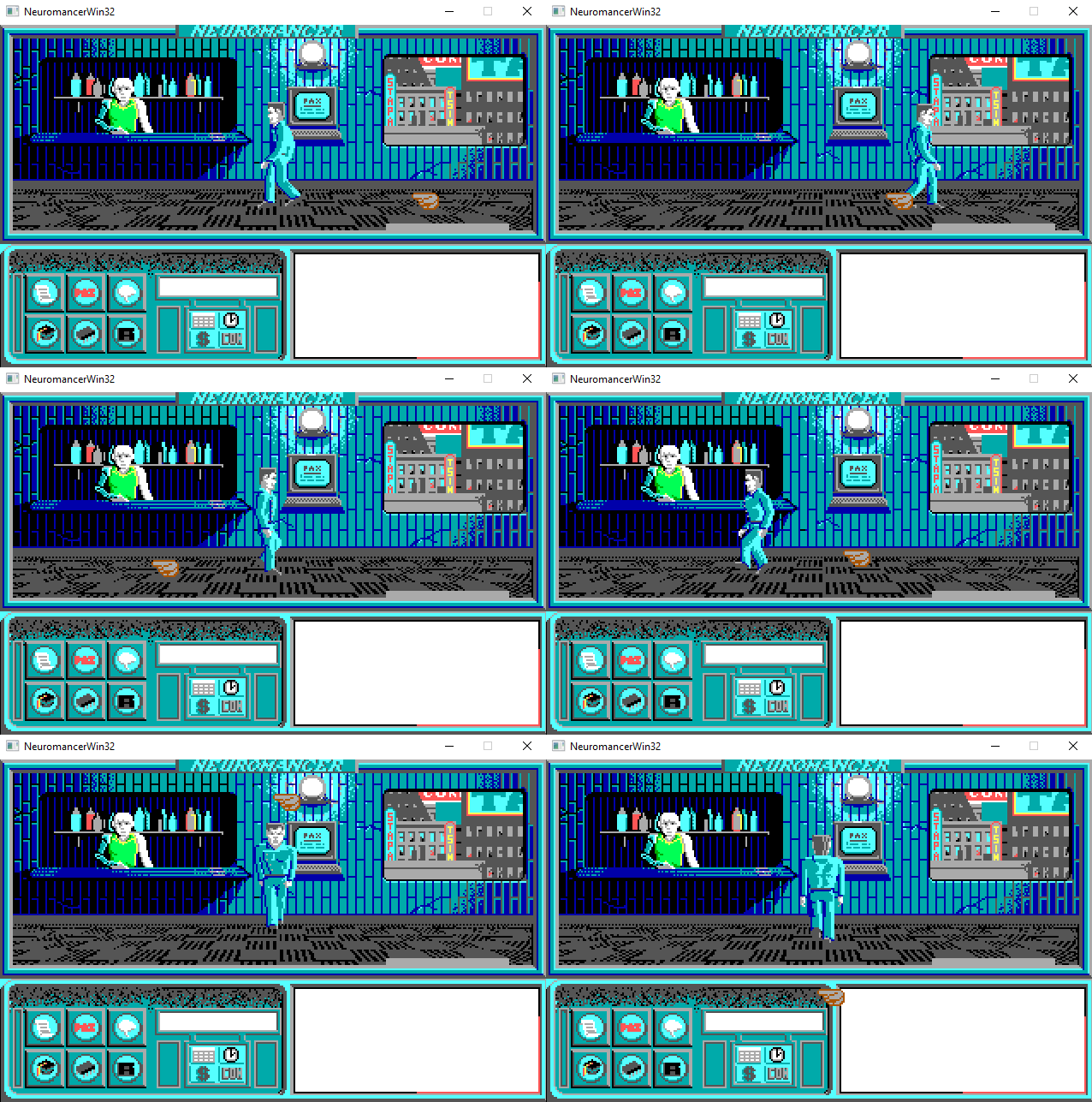
Applying it in my code, I got the right picture, and after that I started to revive the main character. In fact, all the code associated with the control of the character (the mouse and the keyboard), its animation and movement, I wrote on my own, without looking at the original.
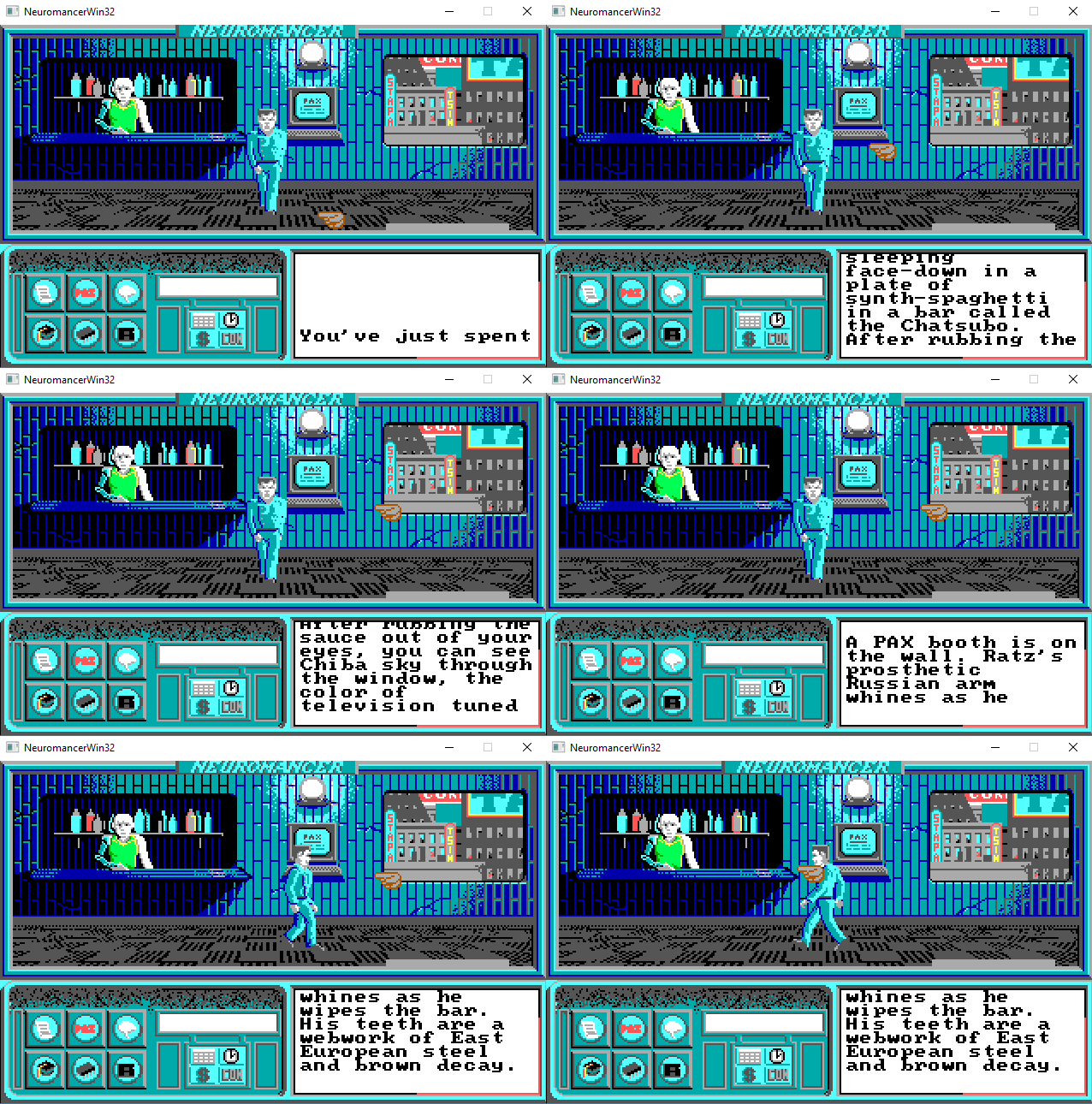
I wrote down the text intro for the first level. Let me remind you that string resources are stored in .BIHfiles. The unpacked .BIH-files consist of a header and variable size sequence null terminated strings. Investigating the original code that plays the intro, I found out that the offset of the beginning of the text part in the .BIHfile is contained in the fourth Word header. The first line is the intro:
typedefstructbih_hdr_t {uint16_t unknown[3];
    uint16_t text_offset;
} bih_hdr_t;
...
uint8_t r1_bih[12288];
assert(resource_manager_load("R1.BIH", r1_bih));
bih_hdr_t *hdr = (bih_hdr_t*)r1_bih;
char *intro = r1_bih + hdr->text_offset;
Further, relying on the original, I implemented splitting the original line into substrings so that they fit into the area for displaying text, scrolling these lines, and waiting for input before issuing the next batch.
At the time of publication, beyond what has already been described in three parts, I figured out the sound reproduction. So far it is only in my head and it will take some time to implement it in my project. So the fourth part is likely to be entirely about the sound. I also plan to tell a little about the architecture of the project, but let's see how it goes.
Reverse "Neuromant". Part 4: Sound, Animation, Huffman, Github
