Writing a driver for a homemade USB device
The purpose of this article is a step-by-step demonstration of the development process of the entire set of software necessary for organizing the communication of a home-made device with a computer via USB.
At the moment, most hams implement this type of connection using the USB adapter chips in RS232, thus organizing communication with their device through the virtual COM port driver supplied with the adapter chip. The disadvantages of this approach I think are understandable. This is at least an extra chip on the board and the restrictions imposed by this chip and its driver.
I would like to highlight the whole process of organizing such interaction, as it should be done, and how it is done in all serious devices.
In the end, now is the 21st century, there is a USB module in almost all microcontrollers. It is about how to quickly use this module and this article will be.
Since we need the device itself to demonstrate the process of writing a USB device driver, we will choose one of the common debug boards available in Russia. I have this board manufactured by OLIMEX model LPC-P2148. The base of the board is the NXP microcontroller LPC2148 architecture of the ARM7TDMI architecture. All information on the board can be obtained on the manufacturer's website at the following link. This is how she looks.

The choice of the controller and the debug board is absolutely not important since the process of developing interaction between the OS on a personal computer and the board itself does not depend on this. The microcontroller firmware development environment will use KEIL version 4.23, which is also not important. As a result, it is planned to implement only the BULK type of transmission. We will read the data array from the device to the computer, and we will transfer the status of the LEDs to the device so that it is clear that the board is responding to our commands.
For ease of understanding, we will divide further actions at the stage and we will go through them in order.
1. Adapting the finished example of a USB device to our board in order to make sure that the board is working and the USB channel is also functional. It will be like our starting point.
2. Changing the firmware of the board so that it becomes an unknown device for Windows that requires a manufacturer's driver.
3. Adapting a basic template, an empty driver, so that Windows can correctly install it, to service our device.
4. Implementation of driver interaction with the user application.
5. Writing a Windows console application to work with our driver, and therefore a connected USB device.
6. Filling the entire system with the necessary functions.
What will not be in this article. I will not describe the operating mechanisms of the OS that allow me to find and install the right driver. There will be no description of how to build firmware in the KEIL environment. There will be no description of the parameters of the USB descriptors and generally nothing will be said about how the firmware works. In the end I will provide links to all sources of information, my source codes and collected binary files. Thus, a description of any moment not covered by this article can be easily found at the indicated sources. Understand correctly, it is unrealistic to put in one article detailed information on all these topics. Moreover, there are more competent sources.
For the basis of the firmware for our project, we will take the RTX_Memory example supplied with KEIL. This example, when it successfully works, will allow us to connect our board to a computer and it will be visible there like a regular USB flash drive. Thus, we get the firmware, which obviously correctly configures the USB module and all peripherals necessary for the processor.
The project is located in the folder ARM \ Boards \ Keil \ MCB2140 \ RL \ USB \. The paths hereinafter I will indicate relative to the main folder where the KEIL environment is installed.
We copy the project to a separate place, upload it to KEIL and assemble it. Must get together without errors. As a result, we got a HEX file that we can flash using the FlashMagic utility.
True, you can not flash it yet, as it is obvious that it will not work on our board.
If we compare the circuit of our board and the board for which an example was written, and this is the KEIL model MCB2140, we can see the differences in the connection of the D + line suspender.
On the MCB2140, it is always pulled up to 3.3V, and on the LPC-P2148, this pull-up is controlled by a microcontroller through a transistor.
Schematics of both boards are available at www.olimex.com and www.keil.com, respectively.
For simplicity, we will slightly modify the initialization code so that our board always turns on the D + line pull-up when it is turned on, which will be indicated by the USB_LINK LED.
In the USB_Init () procedure, disconnect the CONNECT line from the USB module and manage it ourselves. And since there is also a USB_LINK LED on the same transistor, it turns out that when we turn it on, the D + line lift will turn on automatically.
In addition, our board has fewer LEDs than the MCB2140. Therefore, their purpose also needs to be redefined. At this point, I reassigned them simply to indicate read / write processes.
Since we do not have LED_CFG and LED_SUSP indicators, we comment on their use everywhere according to the project code.
Now you can assemble the project and flash it into the controller. By connecting the board to the computer, it is clear that it recognizes it as an external drive and another disk appears in the system that is only about 25KB in size and with the readme.txt file.
At this point, the first stage can be considered completed.
At the moment, we have a device that on any computer with any OS will be recognized as an external USB drive. But we need Windows to not know how to work with our device and require a driver. The fact that the connected device belongs to the drive class is indicated by the Interface class parameter located in the interface descriptor.
If you open the usbdesc.c file and find this parameter there, you will see that it has the value USB_DEVICE_CLASS_STORAGE.
Replace it with USB_DEVICE_CLASS_VENDOR_SPECIFIC, and replace the two fields following it with zeros.
Now reassembling the project and flashing the board, we will see that Windows no longer knows that our device is a drive and requires the provision of a suitable driver.
There may be a problem. The fact is that Windows, having remembered the VID and PID of our device the previous time, as related to the external storage device, can continue to put its driver on it without paying attention to the fact that the device class has changed. The solution is simple. If the board is still defined as a drive, find it in the USB branch of the device manager and remove the driver manually. After that, the OS should start asking for a driver.
So, we have a working USB device for which you need to provide a driver.
To begin with, we will write the simplest driver that will not do anything useful, except to boot into the system when our device appears on the USB bus. The driver will have a minimum code to only boot correctly and unload the system.
We will write the driver in the most minimalistic way. The code itself will be edited in notepad, and will be collected on the command line.
To get started, you need to download the driver development kit from the Microsoft website. It is called the Windows Driver Kit. I am using the WDK version 7600.16385.1.
After installation, we will get many examples, environment for assembly and documentation. In the start menu, you need to find the WDK section and there Build Environments. These are the so-called build environments. In fact, they provide us with a console that is already configured to collect drivers for the desired system.
You see that there is a separate folder for each OS where a couple of Checked and Free environments are located. The first for the so-called Checked systems, collects a driver with additional information useful for debugging.
The second collects the driver release, which is then used.
I will continue to use the x86 Checked Build Environment from windows XP. This will give me a universal driver that works correctly on systems from Windows XP and newer.
Now let's look for a template with which it would be most convenient to start.
The most suitable candidate was an example for a certain OSR USB-FX2 learning kit. What kind of board is this, I absolutely have no idea, but the example we need is in the WDK along the path src \ usb \ osrusbfx2 \. The most interesting thing is that this is not just an example, but a step-by-step tutorial on how to make a driver for this board. Just what we need. Let’s go deeper into the kmdf \ sys directory and see that there are all the steps and are in daddies. You can read more about them in the example description located in the osrusbfx2.htm file.
Here I will make a small digression to make the following actions a little clearer.
The fact is that since the advent of Windows NT, something has changed in the process of writing a driver. In those days, we had to directly use the functions of the OS kernel and often, just to make a dummy capable of loading, unloading, responding to PNP events, etc. basic functions, I had to learn a lot of things and fly out to BSOD more than once. Then Microsoft made a model called the Windows Driver Model that introduced some kind of standard or something, what the driver should look like. There was no particular relief, personally, from this I did not feel. And the next step was a framework called the Windows Driver Framework. And thanks to this, life has become much easier. Now the framework takes care of the implementation of all the basic actions necessary to service the main events, and all that remains for us is to correctly add the functions we need. It is this technology that we will use.
We start from the first step. Launch the “x86 Checked Build Environment” and use the “cd” command to move to the WinDDK \ 7600.16385.1 \ src \ usb \ osrusbfx2 \ kmdf \ sys \ step1 \ folder.
Run the build -ceZ command.
The build process occurs, and as a result, the objchk_wxp_x86 folder is created (its name depends on the selected environment), where we find the file with the sys extension. This is our driver. To install it, we need an INF file. Find it in the final folder of the same project. It is called osrusbfx2.inf. The only problem is that it is designed for the board from the example. In order for this file to be able to install the driver for our board, simply change the VID and PID values in it everywhere to those that are written in the USB device descriptor in the usbdesc.c file. Looking through the INF file with your eyes, you will notice that the WdfCoInstaller01009.dll file is still required to install the driver. It is also supplied by WDK.
So, copy three files to a separate folder: the compiled SYS, INF, WdfCoInstaller01009.dll.
We connect our board to the computer, and when asked by Windows about the path to the driver, we indicate this folder.
We observe the usual process of copying driver files and our device appears under the Sample Device class in the device manager. Everything, the operating system is satisfied!
And here a question may arise, but how do we know that our code is executing. And in other words, I would like to get some kind of feedback from the driver. That's right, the time has come to add debugging information to the driver in order to understand what is going on.
In kernel mode, the KdPrint () function outputs debugging information. Its use is the same as the well-known printf (). To see its output, you need to install the program DbgView. It is available on the Microsoft website athttp://technet.microsoft.com/en-us/sysinternals/bb896647 . Just keep it running and you will see the output of all debugging information from the kernel mode of the OS. I usually configure the filter so that only messages from the module I need are displayed. In my version of Step_1, I added the output to the DeviceEntry () and DeviceAdd () procedures so that it simply writes which function was called. By connecting and disconnecting the board, in the DbgView window you can clearly see in what order this happens.

As you know, device drivers work in kernel mode (with some exceptions), and our applications in user mode. The same mechanism is used for interaction as for working with files. In other words, for each connected device in the system there is a symbolic name by which it can be opened like a regular file. Well, then use the usual procedures for working with files such as ReadFile () and WriteFile (). In this part, we will add functionality to our driver that allows you to open, close, write and read data from it.
We will save the recorded data so that later we can give them back during the read operation.
The first thing to do is register your callback function for the EvtDevicePrepareHardware event, which the PnP manager will call after the device enters the uninitialized state of D0 and before making it available to the driver. In fact, this means a very simple thing, we stuck the device, the driver booted, but maybe your device requires some configuration before it becomes possible to work with it. We will do this kind of tuning in this event. As applied to USB, at least you need to select the desired configuration. So, we register our function. To do this, add the following code to DriverEntry:
The second one. If you pay attention to the WdfDeviceCreate procedure call from the driver code of the previous paragraph, you will notice that the second parameter of this procedure is passed the constant WDF_NO_OBJECT_ATTRIBUTES. This means that the device object does not have any attributes. But in real life, we need at least one attribute. This is the so-called device context. Simply put, this is some kind of structure that relates to a specific instance of a device supported by the driver, and will be further available to us almost anywhere in the driver. For example, it may contain some kind of buffer. And it is attached to the device object, not the driver, because Several identical devices can be connected to the computer, which will be served by the same driver, but all of them will have their own device object.
So, we will create a context structure, and initialize with it, the attribute parameter, passed further to WdfDeviceCreate: Third. Now you need to create an interface through which the driver becomes available to user-mode programs. Previously, the programmer himself had to hard-code the name by which access to the device through the CreateFile procedure could be open. Now everything has become easier. We only need to create an interface by calling one procedure, and the generated GUID is used to identify it. Further in user mode we will use the same GUID to get the device file name. So, here is our GUID and the code linking it to the interface:
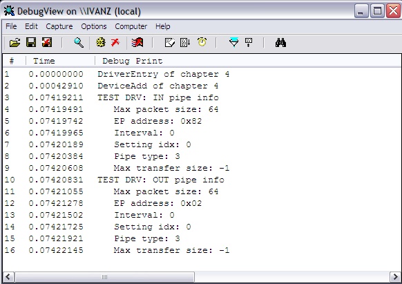
Last thing. In the first paragraph, we registered a procedure that processes the EvtDevicePrepareHardware event. Now you need to write it. I will not rewrite its text in an article, I think it will be easier to look in the source code. I can only say that in this procedure, we prepare everything that is needed for the subsequent operation of the driver with the connected device. Specifically, we create an object of the USB device, select the desired configuration, and save the channel identifiers related to the BULK endpoints of the interface implemented in the device in the device context. We will need these identifiers later, to implement data transfer. For clarity, I added the output of channel parameters to DbgView. You may notice that their parameters are nothing more than the same values that we specified in the endpoint descriptors in the usbdesc.h file of the firmware.
So, now you can rebuild the driver again, and update it in the system. At the moment, our driver may no longer just boot. He already knows how to configure the connected device, and, most importantly, has become available for programs from user mode.
5. We work with the driver from user mode.
Now we will write a simple console program that will only try to access our driver. As you remember, at the moment, our driver does not know how to do anything else, except to give an opportunity to gain access to itself.
Work with devices is reduced to opening them as a regular file, and writing and reading data using the usual WriteFile and ReadFile procedures. There is also a very useful procedure DeviceIoControl for organizing interaction with the driver, which goes beyond the format of working with files, but we will not use it. The file is opened by the usual call to CreateFile, only we need the file name. And here we will come in handy GUID, which we tied to the driver interface. I will not describe the entire procedure for obtaining a name through a GUID, and I honestly admit that I completely took it from the WDK examples. The GetDevicePath procedure receives a GUID and returns the full path corresponding to it.
The file is open. Add a couple of calls that will record and read a dozen bytes from the file.
But back to our driver. In the user program, we already write to the driver and read from it, but the driver code itself knows nothing about it. Correct the situation.
The logic here is the same as with EvtDevicePrepareHardware. We need to register callback functions that will be called when the procedures for reading from the driver or writing to it occur. This is done in EvtDeviceAdd. It is necessary to initialize the I / O queue, fill its fields with pointers to our callback functions, and create it by attaching it to the device object. Go:
In addition to declaring read and write procedures, you must remember to implement them. At this stage, I just set up stubs that output the transferred data to DbgView and give an array of 10 bytes when reading. You can look at their code in source codes. There is nothing interesting there, just advise you to pay attention to working with memory. It is necessary according to certain rules to receive buffers since Our data moves between the kernel and user modes. The screenshot clearly shows how we send data to the driver and they appear in the DbgView window. Then we read the package from the driver and get it in the output of the console application.
6. Making the driver useful.
So the time has come to make our driver useful. At the moment, he is communicating with user mode but does not work with a real device. And all that remains for us to do is to add a code that transmits data to the device in the recording procedure, and a code that receives data from the device in the reading procedure. In the source you see how the procedures serving input / output in the driver have changed very slightly. We just transfer our buffers further to the USB kernel subsystem, and it will do everything as it should.
Before starting the actual transfer of data between the PC and the device, we still need to change the firmware of the device so that it somehow responds to our data.
Let's change the code a little in the processing of the data reception event so that if the first received byte is 0x01 then turn on LED_1, and if it is 0x02 then turn on LED_2. And since After writing to the device, we immediately read 10 bytes from it, then we will add this code too. Please note that we send the packet for transmission in the processing event of the incoming packet. This is such a feature of the USB module. We need to give him data in advance in order to enable him to execute an IN transaction. And for clarity, we will pass two different arrays. We change the contents of MSC_BulkOut () as follows: And in the procedure MSC_BulkIn () we comment out the entire code, leaving it completely empty. The result of the entire bunch you see in the screenshot. At the same time, the board itself blinks with two LEDs.
That's all. We wrote firmware and a full driver for our own USB device. If you start the transfer in blocks of 4k, you can achieve a speed of 800 Kb / s.
As you can see, the driver text is quite simple and contains only about 250 lines.
In the article, I described only the basic steps that you need to take to get a working driver. More detailed information on the procedures used must be read in the WDK. Moreover, now it has become quite pleasant to read this documentation and they are replete with examples.
The full archive with source codes can be downloaded here.
The archive contains folders named by points, each contains the final result, which we achieved in the corresponding paragraph.
I hope the article turned out to be unlike the guide "how to draw an owl", and someone will find it useful.
At the moment, most hams implement this type of connection using the USB adapter chips in RS232, thus organizing communication with their device through the virtual COM port driver supplied with the adapter chip. The disadvantages of this approach I think are understandable. This is at least an extra chip on the board and the restrictions imposed by this chip and its driver.
I would like to highlight the whole process of organizing such interaction, as it should be done, and how it is done in all serious devices.
In the end, now is the 21st century, there is a USB module in almost all microcontrollers. It is about how to quickly use this module and this article will be.
Since we need the device itself to demonstrate the process of writing a USB device driver, we will choose one of the common debug boards available in Russia. I have this board manufactured by OLIMEX model LPC-P2148. The base of the board is the NXP microcontroller LPC2148 architecture of the ARM7TDMI architecture. All information on the board can be obtained on the manufacturer's website at the following link. This is how she looks.
The choice of the controller and the debug board is absolutely not important since the process of developing interaction between the OS on a personal computer and the board itself does not depend on this. The microcontroller firmware development environment will use KEIL version 4.23, which is also not important. As a result, it is planned to implement only the BULK type of transmission. We will read the data array from the device to the computer, and we will transfer the status of the LEDs to the device so that it is clear that the board is responding to our commands.
For ease of understanding, we will divide further actions at the stage and we will go through them in order.
1. Adapting the finished example of a USB device to our board in order to make sure that the board is working and the USB channel is also functional. It will be like our starting point.
2. Changing the firmware of the board so that it becomes an unknown device for Windows that requires a manufacturer's driver.
3. Adapting a basic template, an empty driver, so that Windows can correctly install it, to service our device.
4. Implementation of driver interaction with the user application.
5. Writing a Windows console application to work with our driver, and therefore a connected USB device.
6. Filling the entire system with the necessary functions.
What will not be in this article. I will not describe the operating mechanisms of the OS that allow me to find and install the right driver. There will be no description of how to build firmware in the KEIL environment. There will be no description of the parameters of the USB descriptors and generally nothing will be said about how the firmware works. In the end I will provide links to all sources of information, my source codes and collected binary files. Thus, a description of any moment not covered by this article can be easily found at the indicated sources. Understand correctly, it is unrealistic to put in one article detailed information on all these topics. Moreover, there are more competent sources.
1. Adapting the RTX_Memory Example to the OLIMEX LPC-P2148 Board
For the basis of the firmware for our project, we will take the RTX_Memory example supplied with KEIL. This example, when it successfully works, will allow us to connect our board to a computer and it will be visible there like a regular USB flash drive. Thus, we get the firmware, which obviously correctly configures the USB module and all peripherals necessary for the processor.
The project is located in the folder ARM \ Boards \ Keil \ MCB2140 \ RL \ USB \. The paths hereinafter I will indicate relative to the main folder where the KEIL environment is installed.
We copy the project to a separate place, upload it to KEIL and assemble it. Must get together without errors. As a result, we got a HEX file that we can flash using the FlashMagic utility.
True, you can not flash it yet, as it is obvious that it will not work on our board.
If we compare the circuit of our board and the board for which an example was written, and this is the KEIL model MCB2140, we can see the differences in the connection of the D + line suspender.
On the MCB2140, it is always pulled up to 3.3V, and on the LPC-P2148, this pull-up is controlled by a microcontroller through a transistor.
Schematics of both boards are available at www.olimex.com and www.keil.com, respectively.
For simplicity, we will slightly modify the initialization code so that our board always turns on the D + line pull-up when it is turned on, which will be indicated by the USB_LINK LED.
In the USB_Init () procedure, disconnect the CONNECT line from the USB module and manage it ourselves. And since there is also a USB_LINK LED on the same transistor, it turns out that when we turn it on, the D + line lift will turn on automatically.
In addition, our board has fewer LEDs than the MCB2140. Therefore, their purpose also needs to be redefined. At this point, I reassigned them simply to indicate read / write processes.
Since we do not have LED_CFG and LED_SUSP indicators, we comment on their use everywhere according to the project code.
Now you can assemble the project and flash it into the controller. By connecting the board to the computer, it is clear that it recognizes it as an external drive and another disk appears in the system that is only about 25KB in size and with the readme.txt file.
At this point, the first stage can be considered completed.
2. The transition from a USB drive to a unique device.
At the moment, we have a device that on any computer with any OS will be recognized as an external USB drive. But we need Windows to not know how to work with our device and require a driver. The fact that the connected device belongs to the drive class is indicated by the Interface class parameter located in the interface descriptor.
If you open the usbdesc.c file and find this parameter there, you will see that it has the value USB_DEVICE_CLASS_STORAGE.
Replace it with USB_DEVICE_CLASS_VENDOR_SPECIFIC, and replace the two fields following it with zeros.
Now reassembling the project and flashing the board, we will see that Windows no longer knows that our device is a drive and requires the provision of a suitable driver.
There may be a problem. The fact is that Windows, having remembered the VID and PID of our device the previous time, as related to the external storage device, can continue to put its driver on it without paying attention to the fact that the device class has changed. The solution is simple. If the board is still defined as a drive, find it in the USB branch of the device manager and remove the driver manually. After that, the OS should start asking for a driver.
3. We create the basic driver.
So, we have a working USB device for which you need to provide a driver.
To begin with, we will write the simplest driver that will not do anything useful, except to boot into the system when our device appears on the USB bus. The driver will have a minimum code to only boot correctly and unload the system.
We will write the driver in the most minimalistic way. The code itself will be edited in notepad, and will be collected on the command line.
To get started, you need to download the driver development kit from the Microsoft website. It is called the Windows Driver Kit. I am using the WDK version 7600.16385.1.
After installation, we will get many examples, environment for assembly and documentation. In the start menu, you need to find the WDK section and there Build Environments. These are the so-called build environments. In fact, they provide us with a console that is already configured to collect drivers for the desired system.
You see that there is a separate folder for each OS where a couple of Checked and Free environments are located. The first for the so-called Checked systems, collects a driver with additional information useful for debugging.
The second collects the driver release, which is then used.
I will continue to use the x86 Checked Build Environment from windows XP. This will give me a universal driver that works correctly on systems from Windows XP and newer.
Now let's look for a template with which it would be most convenient to start.
The most suitable candidate was an example for a certain OSR USB-FX2 learning kit. What kind of board is this, I absolutely have no idea, but the example we need is in the WDK along the path src \ usb \ osrusbfx2 \. The most interesting thing is that this is not just an example, but a step-by-step tutorial on how to make a driver for this board. Just what we need. Let’s go deeper into the kmdf \ sys directory and see that there are all the steps and are in daddies. You can read more about them in the example description located in the osrusbfx2.htm file.
Here I will make a small digression to make the following actions a little clearer.
The fact is that since the advent of Windows NT, something has changed in the process of writing a driver. In those days, we had to directly use the functions of the OS kernel and often, just to make a dummy capable of loading, unloading, responding to PNP events, etc. basic functions, I had to learn a lot of things and fly out to BSOD more than once. Then Microsoft made a model called the Windows Driver Model that introduced some kind of standard or something, what the driver should look like. There was no particular relief, personally, from this I did not feel. And the next step was a framework called the Windows Driver Framework. And thanks to this, life has become much easier. Now the framework takes care of the implementation of all the basic actions necessary to service the main events, and all that remains for us is to correctly add the functions we need. It is this technology that we will use.
We start from the first step. Launch the “x86 Checked Build Environment” and use the “cd” command to move to the WinDDK \ 7600.16385.1 \ src \ usb \ osrusbfx2 \ kmdf \ sys \ step1 \ folder.
Run the build -ceZ command.
The build process occurs, and as a result, the objchk_wxp_x86 folder is created (its name depends on the selected environment), where we find the file with the sys extension. This is our driver. To install it, we need an INF file. Find it in the final folder of the same project. It is called osrusbfx2.inf. The only problem is that it is designed for the board from the example. In order for this file to be able to install the driver for our board, simply change the VID and PID values in it everywhere to those that are written in the USB device descriptor in the usbdesc.c file. Looking through the INF file with your eyes, you will notice that the WdfCoInstaller01009.dll file is still required to install the driver. It is also supplied by WDK.
So, copy three files to a separate folder: the compiled SYS, INF, WdfCoInstaller01009.dll.
We connect our board to the computer, and when asked by Windows about the path to the driver, we indicate this folder.
We observe the usual process of copying driver files and our device appears under the Sample Device class in the device manager. Everything, the operating system is satisfied!
And here a question may arise, but how do we know that our code is executing. And in other words, I would like to get some kind of feedback from the driver. That's right, the time has come to add debugging information to the driver in order to understand what is going on.
In kernel mode, the KdPrint () function outputs debugging information. Its use is the same as the well-known printf (). To see its output, you need to install the program DbgView. It is available on the Microsoft website athttp://technet.microsoft.com/en-us/sysinternals/bb896647 . Just keep it running and you will see the output of all debugging information from the kernel mode of the OS. I usually configure the filter so that only messages from the module I need are displayed. In my version of Step_1, I added the output to the DeviceEntry () and DeviceAdd () procedures so that it simply writes which function was called. By connecting and disconnecting the board, in the DbgView window you can clearly see in what order this happens.
4. Interaction between kernel and user modes.
As you know, device drivers work in kernel mode (with some exceptions), and our applications in user mode. The same mechanism is used for interaction as for working with files. In other words, for each connected device in the system there is a symbolic name by which it can be opened like a regular file. Well, then use the usual procedures for working with files such as ReadFile () and WriteFile (). In this part, we will add functionality to our driver that allows you to open, close, write and read data from it.
We will save the recorded data so that later we can give them back during the read operation.
The first thing to do is register your callback function for the EvtDevicePrepareHardware event, which the PnP manager will call after the device enters the uninitialized state of D0 and before making it available to the driver. In fact, this means a very simple thing, we stuck the device, the driver booted, but maybe your device requires some configuration before it becomes possible to work with it. We will do this kind of tuning in this event. As applied to USB, at least you need to select the desired configuration. So, we register our function. To do this, add the following code to DriverEntry:
 WDF_PNPPOWER_EVENT_CALLBACKS_INIT(&pnpPowerCallbacks);

 pnpPowerCallbacks.EvtDevicePrepareHardware = EvtDevicePrepareHardware;

 WdfDeviceInitSetPnpPowerEventCallbacks(DeviceInit, &pnpPowerCallbacks);
The second one. If you pay attention to the WdfDeviceCreate procedure call from the driver code of the previous paragraph, you will notice that the second parameter of this procedure is passed the constant WDF_NO_OBJECT_ATTRIBUTES. This means that the device object does not have any attributes. But in real life, we need at least one attribute. This is the so-called device context. Simply put, this is some kind of structure that relates to a specific instance of a device supported by the driver, and will be further available to us almost anywhere in the driver. For example, it may contain some kind of buffer. And it is attached to the device object, not the driver, because Several identical devices can be connected to the computer, which will be served by the same driver, but all of them will have their own device object.
So, we will create a context structure, and initialize with it, the attribute parameter, passed further to WdfDeviceCreate: Third. Now you need to create an interface through which the driver becomes available to user-mode programs. Previously, the programmer himself had to hard-code the name by which access to the device through the CreateFile procedure could be open. Now everything has become easier. We only need to create an interface by calling one procedure, and the generated GUID is used to identify it. Further in user mode we will use the same GUID to get the device file name. So, here is our GUID and the code linking it to the interface:
typedef struct _DEVICE_CONTEXT {

 WDFUSBDEVICE UsbDevice;

 WDFUSBINTERFACE UsbInterface;

 WDFUSBPIPE BulkReadPipe;

 WDFUSBPIPE BulkWritePipe;

} DEVICE_CONTEXT, *PDEVICE_CONTEXT;

WDF_DECLARE_CONTEXT_TYPE_WITH_NAME(DEVICE_CONTEXT, GetDeviceContext)


WDF_OBJECT_ATTRIBUTES_INIT_CONTEXT_TYPE(&attributes, DEVICE_CONTEXT);
DEFINE_GUID(GUID_DEVINTERFACE_OSRUSBFX2, // Generated using guidgen.exe

 0x573e8c73, 0xcb4, 0x4471, 0xa1, 0xbf, 0xfa, 0xb2, 0x6c, 0x31, 0xd3, 0x84);

// {573E8C73-0CB4-4471-A1BF-FAB26C31D384}


status = WdfDeviceCreateDeviceInterface(device,

 (LPGUID) &GUID_DEVINTERFACE_OSRUSBFX2,

 NULL);// Reference String
Last thing. In the first paragraph, we registered a procedure that processes the EvtDevicePrepareHardware event. Now you need to write it. I will not rewrite its text in an article, I think it will be easier to look in the source code. I can only say that in this procedure, we prepare everything that is needed for the subsequent operation of the driver with the connected device. Specifically, we create an object of the USB device, select the desired configuration, and save the channel identifiers related to the BULK endpoints of the interface implemented in the device in the device context. We will need these identifiers later, to implement data transfer. For clarity, I added the output of channel parameters to DbgView. You may notice that their parameters are nothing more than the same values that we specified in the endpoint descriptors in the usbdesc.h file of the firmware.
So, now you can rebuild the driver again, and update it in the system. At the moment, our driver may no longer just boot. He already knows how to configure the connected device, and, most importantly, has become available for programs from user mode.
5. We work with the driver from user mode.
Now we will write a simple console program that will only try to access our driver. As you remember, at the moment, our driver does not know how to do anything else, except to give an opportunity to gain access to itself.
Work with devices is reduced to opening them as a regular file, and writing and reading data using the usual WriteFile and ReadFile procedures. There is also a very useful procedure DeviceIoControl for organizing interaction with the driver, which goes beyond the format of working with files, but we will not use it. The file is opened by the usual call to CreateFile, only we need the file name. And here we will come in handy GUID, which we tied to the driver interface. I will not describe the entire procedure for obtaining a name through a GUID, and I honestly admit that I completely took it from the WDK examples. The GetDevicePath procedure receives a GUID and returns the full path corresponding to it.
The file is open. Add a couple of calls that will record and read a dozen bytes from the file.
But back to our driver. In the user program, we already write to the driver and read from it, but the driver code itself knows nothing about it. Correct the situation.
The logic here is the same as with EvtDevicePrepareHardware. We need to register callback functions that will be called when the procedures for reading from the driver or writing to it occur. This is done in EvtDeviceAdd. It is necessary to initialize the I / O queue, fill its fields with pointers to our callback functions, and create it by attaching it to the device object. Go:
WDF_IO_QUEUE_CONFIG_INIT_DEFAULT_QUEUE(&ioQueueConfig,

 WdfIoQueueDispatchParallel);


ioQueueConfig.EvtIoRead = EvtIoRead;

ioQueueConfig.EvtIoWrite = EvtIoWrite;


status = WdfIoQueueCreate(device,

 &ioQueueConfig,

 WDF_NO_OBJECT_ATTRIBUTES,

 WDF_NO_HANDLE);
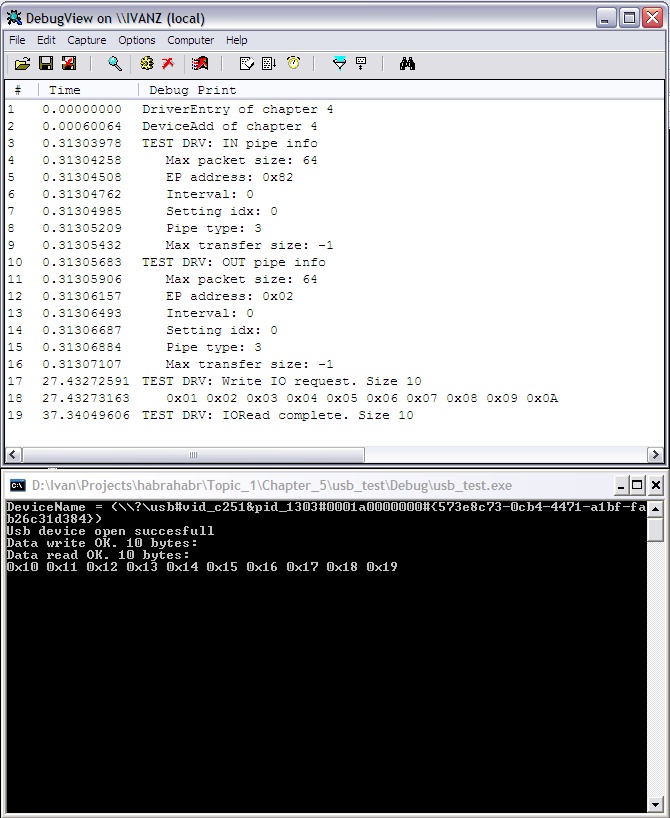
In addition to declaring read and write procedures, you must remember to implement them. At this stage, I just set up stubs that output the transferred data to DbgView and give an array of 10 bytes when reading. You can look at their code in source codes. There is nothing interesting there, just advise you to pay attention to working with memory. It is necessary according to certain rules to receive buffers since Our data moves between the kernel and user modes. The screenshot clearly shows how we send data to the driver and they appear in the DbgView window. Then we read the package from the driver and get it in the output of the console application.
6. Making the driver useful.
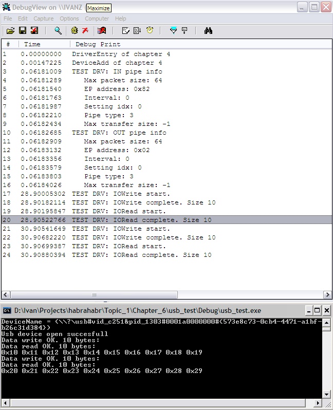
So the time has come to make our driver useful. At the moment, he is communicating with user mode but does not work with a real device. And all that remains for us to do is to add a code that transmits data to the device in the recording procedure, and a code that receives data from the device in the reading procedure. In the source you see how the procedures serving input / output in the driver have changed very slightly. We just transfer our buffers further to the USB kernel subsystem, and it will do everything as it should.
Before starting the actual transfer of data between the PC and the device, we still need to change the firmware of the device so that it somehow responds to our data.
Let's change the code a little in the processing of the data reception event so that if the first received byte is 0x01 then turn on LED_1, and if it is 0x02 then turn on LED_2. And since After writing to the device, we immediately read 10 bytes from it, then we will add this code too. Please note that we send the packet for transmission in the processing event of the incoming packet. This is such a feature of the USB module. We need to give him data in advance in order to enable him to execute an IN transaction. And for clarity, we will pass two different arrays. We change the contents of MSC_BulkOut () as follows: And in the procedure MSC_BulkIn () we comment out the entire code, leaving it completely empty. The result of the entire bunch you see in the screenshot. At the same time, the board itself blinks with two LEDs.
void MSC_BulkOut (void) {


BulkLen = USB_ReadEP(MSC_EP_OUT, BulkBuf);


 LED_Off( LED_RD | LED_WR );

 if( BulkBuf[ 0 ] == 0x01 )

 {

 USB_WriteEP( MSC_EP_IN, (unsigned char*)aBuff_1, sizeof( aBuff_1 ) );

 LED_On( LED_RD );

 }

 else

 if( BulkBuf[ 0 ] == 0x02 )

 {

 USB_WriteEP( MSC_EP_IN, (unsigned char*)aBuff_2, sizeof( aBuff_1 ) );

 LED_On( LED_WR );

 }

}
That's all. We wrote firmware and a full driver for our own USB device. If you start the transfer in blocks of 4k, you can achieve a speed of 800 Kb / s.
As you can see, the driver text is quite simple and contains only about 250 lines.
In the article, I described only the basic steps that you need to take to get a working driver. More detailed information on the procedures used must be read in the WDK. Moreover, now it has become quite pleasant to read this documentation and they are replete with examples.
The full archive with source codes can be downloaded here.
The archive contains folders named by points, each contains the final result, which we achieved in the corresponding paragraph.
I hope the article turned out to be unlike the guide "how to draw an owl", and someone will find it useful.