Remote Follow Focus on Arduino
Once I decided to make Remote Follow Focus for my camera. This is a system that allows you to focus the lens from a certain distance. Thus, the camera can be located on the crane, steadicam or on the shoulder of the operator and at the same time the focus operator (focus puller) is able to rotate the focus ring on the lens remotely. The idea was born by itself when I looked at what can be done with the Arduino.
When all the components arrived, I started assembling the prototype. For this project, I used:
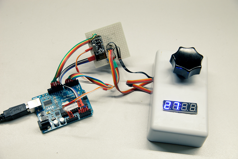
Transmitter (control unit)
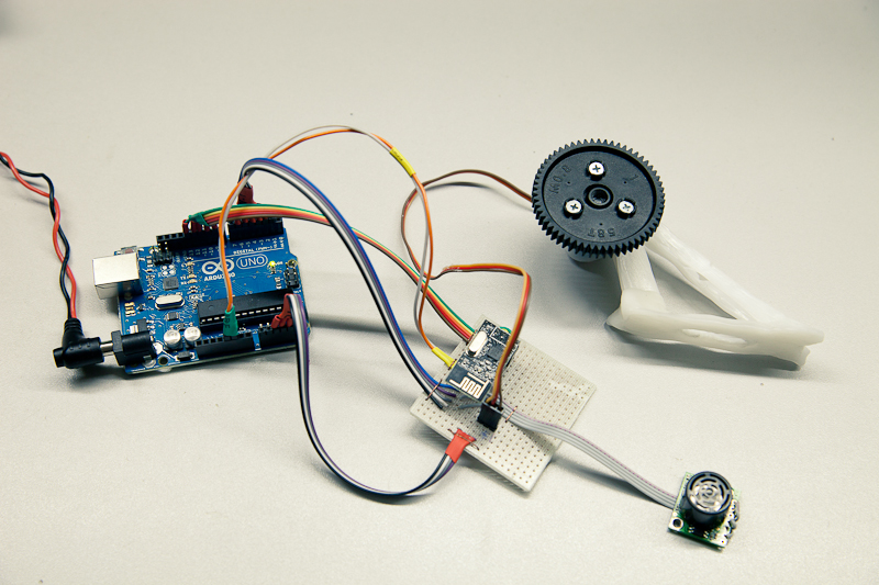
Receiver (execution unit)
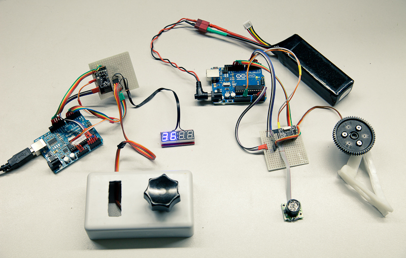
The task involves two blocks - a transmitter and a receiver. The transmitter reads the readings of the variable resistor, smooths them and sends them over the air to the receiver. The receiver receives the packet with the position of the handle of the resistor and rotates the servo in proportion to this value.
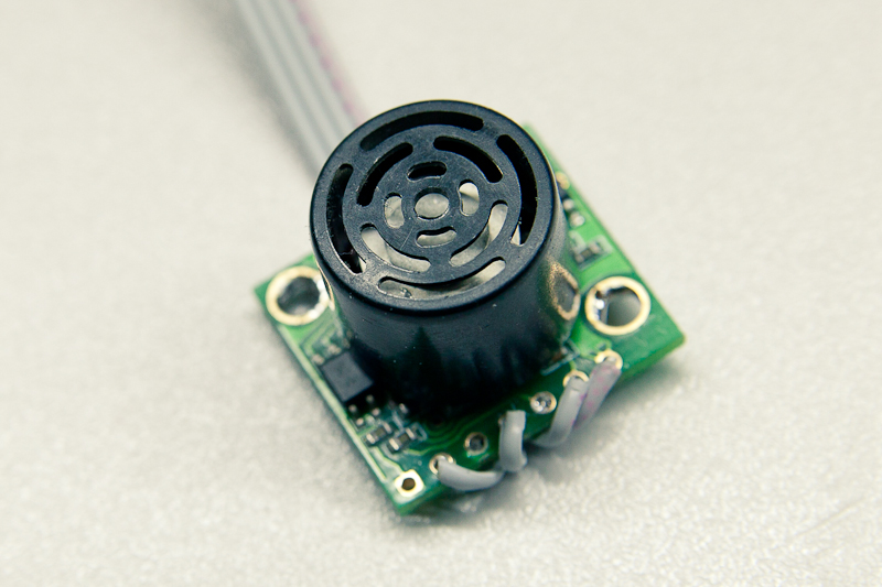
I was lucky and nRF24L01 + can communicate in two-way mode. So I also installed the MaxSonar EZ0 ultrasonic rangefinder on the “receiver”. It measures the distance to the object in front of the camera and sends this number to the “transmitter” - to the control unit. There, this figure is displayed on a 7-segment display. It is supposed to help people manage focus. For example, you can draw a scale around the pen so that you can focus on the numbers.
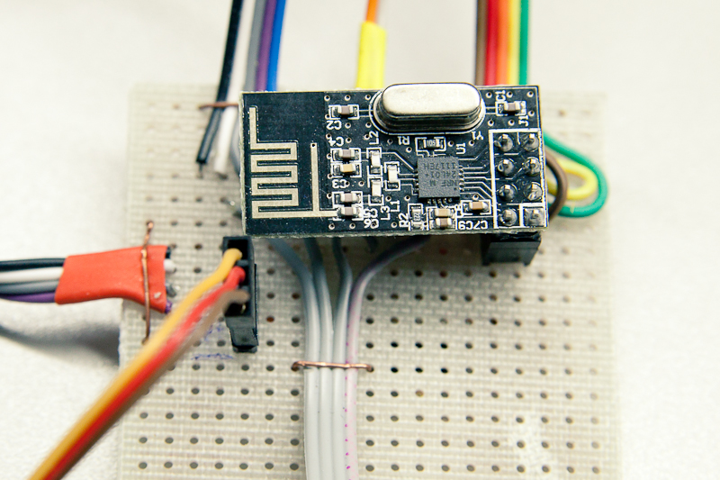
Development board and module with nRF24L01 +
MaxSonar EZ0
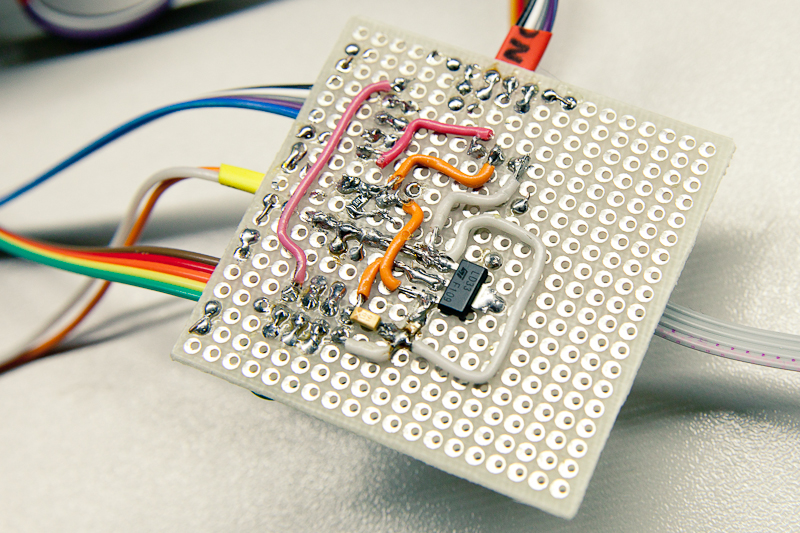
Reverse side of one of the development boards
In the process of working on this project, I encountered many different problems. But almost all of them were heroically overcome.
Here is some of them:
When all the components arrived, I started assembling the prototype. For this project, I used:
- Arduino Duemilanove and Arduino Uno (different only because they were bought with an interval of several years)
- 2 nRF24L01 + transceivers
- Servo
- Gear (0.8 pitch)
- MaxSonar EZ0
- 7-segment segment display
- 10k variable resistor
- 2 voltage regulators 3.3V
- Multiple capacitors and resistors to stabilize power according to voltage regulator and sonar specifications
- Development Boards, Cables, Connectors, Heat Shrink, Wires, Miscellaneous
Transmitter (control unit)
Receiver (execution unit)
The task involves two blocks - a transmitter and a receiver. The transmitter reads the readings of the variable resistor, smooths them and sends them over the air to the receiver. The receiver receives the packet with the position of the handle of the resistor and rotates the servo in proportion to this value.
I was lucky and nRF24L01 + can communicate in two-way mode. So I also installed the MaxSonar EZ0 ultrasonic rangefinder on the “receiver”. It measures the distance to the object in front of the camera and sends this number to the “transmitter” - to the control unit. There, this figure is displayed on a 7-segment display. It is supposed to help people manage focus. For example, you can draw a scale around the pen so that you can focus on the numbers.
Development board and module with nRF24L01 +
MaxSonar EZ0
Reverse side of one of the development boards
In the process of working on this project, I encountered many different problems. But almost all of them were heroically overcome.
Here is some of them:
- Floating value of analog input. For some reason, at the input from the resistor, I get a very large scatter of values at the moment when the handle does not spin. I solved the problem programmatically - I average the values and do a few more tricks. In general, the problem is almost solved. I’ll also try another resistor. The current one seems older than me.
- Low accuracy of servo positioning. Documentation by default suggests positioning the servo with an accuracy of 1 degree. This was not enough for me. Improved the situation with the writeMicroseconds function. It allows you to more accurately rotate the gear.
- Transceivers did not work right away. The problem was pinout on the page with the documentation. I found another page on the network with a working pinout and the radio worked.
- The servo runs jerky when using the serial port in the program. Apparently, interrupts interfere with its timing. And the most convenient way to extract data from MaxSonar was through the serial port. I had to completely rewrite the program for interrupts and use the PWM output. From the analog output, counting the distance turned out badly.
- The PWM output of MaxSonar is not stable. There is a range of values. But so far this is not critical for me. In the future, I plan to solve this problem more radically. I don’t know how yet.
- The 7-segment display managed to upgrade to another baud rate itself. For two days I thought that it just burned down. But then I thought up to double-check all baud rate and saw that he was still working. In general, it does not work very stably. Perhaps due to the fact that I'm using SoftwareSerial. Or due to the fact that the frequency generators for him and Arduino are different.