Notes of the amateur, or the Tale of how the FPGA Scala-developer has configured
- Tutorial
 For a long time I dreamed of learning how to work with FPGA, I watched. Then I bought a debug board, wrote a couple of hello worlds, and put the board in a box, because it was not clear what to do with it. Then the idea came: let's write a composite video signal generator for an ancient CRT TV. The idea, of course, is funny, but I really don’t know Verilog, and I’ll still have to remember it, and I don’t need this generator so much ... And recently I wanted to look towards RISC-V software processors. You need to start somewhere, and the Rocket Chip code (this is one of the implementations) is written in Chisel - this is the DSL for Scala. Then I suddenly remembered that I had been working professionally at Scala for two years and understood: the time has come ...
So, if you want to read the story of the life of the pliers, the digital multimeter and the oscilloscope, which is aware of itself, then welcome to the cat.
So what will be in this article? In it, I will describe my attempts to generate a composite PAL video signal (why PAL? I just got a good tutorial just for generating PAL) on the Mars Rover 2 by nckma . I won't say anything about RISC-V in this article. :)
First, a little about Scala and Chisel: Scala is a language that runs on top of the Java Virtual Machine and transparently uses existing Java libraries (although Scala.js and Scala Native are also available). When I first began to study it, I got the feeling that it was such a very viable hybrid of “pluses” and Haskell (however, colleagues do not share this opinion) - it’s a painfully advanced type system and laconic language, but because of the need to cross functionalism with OOP The abundance of language constructs in some places evoked memories of C ++. However, do not be afraid of Scala - it is a very laconic and safe language with a powerful type system, which at first you can simply write as in improved Java. And as far as I know, Scala was originally developed as a language for easy creation.Domain Specific Languages is when you describe, say, digital equipment or notes in a formal language, and this language looks quite logical from the point of view of its subject area. And then you suddenly find out that it was the correct code on Scala (well, or Haskell) - just kind people wrote a library with a convenient interface. Chisel is just such a Scala library that allows you to describe digital logic on a convenient DSL, and then run the resulting Scala code and generate the code on Verilog (or something else), which can be copied to the Quartus project. Well, or immediately run the standard scala-style unit-tests, which themselves simulate testbenches and issue a report on the results.
For acquaintance with digital circuitry, I highly recommend this book (it already exists in the printed Russian version). In fact, my systematic acquaintance with the FPGA world almost ends on this book, so constructive criticism is welcome in the comments (however, I repeat, the book is wonderful: it tells from the basics to creating a simple, contourized processor. And there are pictures there;)). Well, according to Chisel there is a good official tutorial .
Disclaimer: the author is not responsible for the equipment that has been lost, and if you decide to repeat the experiment - check the signal levels with an oscilloscope, alter the analog part, etc. And in general - follow the safety precautions. (I, for example, in the process of writing the article realized that my legs are limbs too, and I don’t have to stick them to the central heating battery, holding my hand over the output of the board ...) By the way, this infection also interfered with the TV in the next room during debugging ...
Project Setup
Write code, we'll be in IntelliJ Idea Community Edition , as your build system will sbt , therefore, create a directory, we set to .gitignore, project/build.properties, project/plugins.sbthere and
defscalacOptionsVersion(scalaVersion: String): Seq[String] = {
  Seq() ++ {
    // If we're building with Scala > 2.11, enable the compile option//  switch to support our anonymous Bundle definitions://  https://github.com/scala/bug/issues/10047CrossVersion.partialVersion(scalaVersion) match {
      caseSome((2, scalaMajor: Long)) if scalaMajor < 12 => Seq()
      case _ => Seq("-Xsource:2.11")
    }
  }
}
name := "chisel-example"
version := "1.0.0"
scalaVersion := "2.11.12"
resolvers ++= Seq(
  Resolver.sonatypeRepo("snapshots"),
  Resolver.sonatypeRepo("releases")
)
// Provide a managed dependency on X if -DXVersion="" is supplied on the command line.val defaultVersions = Map(
  "chisel3" -> "3.1.+",
  "chisel-iotesters" -> "1.2.+"
  )
libraryDependencies ++= (Seq("chisel3","chisel-iotesters").map {
  dep: String => "edu.berkeley.cs" %% dep % sys.props.getOrElse(dep + "Version", defaultVersions(dep)) })
scalacOptions ++= scalacOptionsVersion(scalaVersion.value)
Now we’ll open it in the Idea and ask to import the sbt-project - while sbt will download the necessary dependencies.
First modules
PWM
To begin, let's try to write a simple PWM . The logic I had was approximately the following: in order to generate a signal of the fill factor n / m, initially we put in register 0 and we will add to it n each step. When the register value exceeds m - subtract m and give a high level for one clock cycle. Actually, it will fail if n> m, but we will consider this to be an undefined behavior that is needed to optimize the actually used cases.
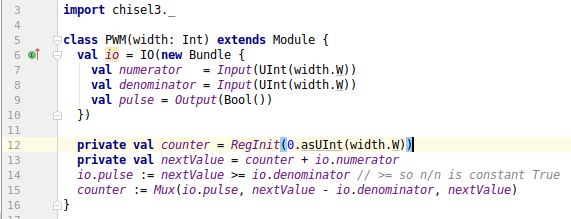
I will not retell the whole beginner's guide - it is read in half an hour, I will just say that in order to describe the module, we need to import chisel3._and inherit from the abstract class Module. It is abstract because we need to describe it Bundleunder the name io- it will contain the entire interface of the module. At the same time, we will have implicit entrances clockand reset- it is not necessary to describe them separately. Here is what happened:
import chisel3._
classPWM(width: Int) extendsModule{
  val io = IO(newBundle {
    val numerator   = Input(UInt(width.W))
    val denominator = Input(UInt(width.W))
    val pulse = Output(Bool())
  })
  privateval counter = RegInit(0.asUInt(width.W))
  privateval nextValue = counter + io.numerator
  io.pulse := nextValue > io.denominator
  counter := Mux(io.pulse, nextValue - io.denominator, nextValue)
}
Notice, we call the method .Won the ordinary int in order to get the port width, and .asUInt(width.W)we generally call the method on the integer literal! How is this possible? - well, in Smalltalk we would simply define the Integer class (or whatever it is called), but in the JVM, we still don’t have an entire object - there are also primitive types, and Scala understands this (and, moreover, there are third-party classes that we can not change). Therefore, there are various implicit s: in this case Scala probably finds something like
implicitclassBetterInt(n: Int) {
  defW: Width = ...
}
in the current field of view, therefore, the usual inta appear superpowers. Here is one of the features that makes Scala more concise and convenient for creating DSL.
import chisel3.iotesters._
import org.scalatest.{FlatSpec, Matchers}
objectPWMSpec{
  classPWMTesterConstant(pwm: PWM, denum: Int, const: Boolean)extendsPeekPokeTester(pwm) {
    poke(pwm.io.numerator, if (const) denum else0)
    poke(pwm.io.denominator, denum)
    for (i <- 1 to 2 * denum) {
      step(1)
      expect(pwm.io.pulse, const)
    }
  }
  classPWMTesterExact(pwm: PWM, num: Int, ratio: Int) extendsPeekPokeTester(pwm) {
    poke(pwm.io.numerator, num)
    poke(pwm.io.denominator, num * ratio)
    val delay = (1 to ratio + 2).takeWhile { _ =>
      step(1)
      peek(pwm.io.pulse) == BigInt(0)
    }
    println(s"delay = $delay")
    for (i <- 1 to 10) {
      expect(pwm.io.pulse, true)
      for (j <- 1 to ratio - 1) {
        step(1)
        expect(pwm.io.pulse, false)
      }
      step(1)
    }
  }
  classPWMTesterApproximate(pwm: PWM, num: Int, denom: Int) extendsPeekPokeTester(pwm){
    poke(pwm.io.numerator, num)
    poke(pwm.io.denominator, denom)
    val count = (1 to 100 * denom).map { _ =>
      step(1)
      peek(pwm.io.pulse).toInt
    }.sum
    val diff = count - 100 * num
    println(s"Difference = $diff")
    expect(Math.abs(diff) < 3, "Difference should be almost 0")
  }
}
classPWMSpecextendsFlatSpecwithMatchers{
  importPWMSpec._
  behavior of "PWMSpec"deftestWith(testerConstructor: PWM => PeekPokeTester[PWM]): Unit = {
    chisel3.iotesters.Driver(() => newPWM(4))(testerConstructor) shouldBe true
  }
  it should "return True constant for 1/1" in {
    testWith(newPWMTesterConstant(_, 1, true))
  }
  it should "return True constant for 10/10" in {
    testWith(newPWMTesterConstant(_, 10, true))
  }
  it should "return False constant for 1/1" in {
    testWith(newPWMTesterConstant(_, 1, false))
  }
  it should "return False constant for 10/10" in {
    testWith(newPWMTesterConstant(_, 10, false))
  }
  it should "return True exactly once in 3 steps for 1/3" in {
    testWith(newPWMTesterExact(_, 1, 3))
  }
  it should "return good approximation for 3/10" in {
    testWith(newPWMTesterApproximate(_, 3, 10))
  }
}PeekPokeTester- This is one of the three standard testers in Chisel. It allows you to set the values at the inputs of the DUT (device under test) and check the values at the outputs. As we see, for tests, the usual ScalaTest is used and the tests take up places 5 times more than the implementation itself, which, in principle, is normal for software. However, I suspect that experienced developers of equipment "cast in silicon" will only smile with such a microscopic number of tests. Run and oops ...
Circuit state created
[info] [0,000] SEED 1529827417539
[info] [0,000] EXPECT AT 1   io_pulse got 0 expected 1 FAIL
...
[info] PWMSpec:
[info] PWMSpec
[info] - should returnTrueconstantfor1/1
[info] - should returnTrueconstantfor10/10 *** FAILED ***
[info]   false was not equal totrue (PWMSpec.scala:56)
[info] - should returnFalseconstantfor1/1
[info] - should returnFalseconstantfor10/10
[info] - should returnTrue exactly once in3 steps for1/3
[info] - should return good approximation for3/10
Yeah, let's fix the io.pulse := nextValue > io.denominatorsign on the PWM line >=, restart the tests - it works! I am afraid that experienced digital equipment developers will want to kill me for such a frivolous attitude to design (and some software developers will happily join them) ...
Pulse generator
We also need a generator that will generate synchronization pulses for the "half frames". Why "semi-"? because odd strings are transmitted first, then even strings (well, or vice versa, but we are not into fat now).
import chisel3._
import chisel3.util._
classOneShotPulseGenerator(val lengths: Seq[Int], val initial: Boolean) extendsModule{
  // Add sentinel value here, so no output flip required after the last stateprivateval delayVecValues = lengths.map(_ - 1) :+ 0val io = IO(newBundle {
    val signal = Output(Bool())
  })
  privateval nextIndex = RegInit(1.asUInt( log2Ceil(delayVecValues.length + 1).W ))
  privateval countdown = RegInit(delayVecValues.head.asUInt( log2Ceil(lengths.max + 1).W ))
  privateval output    = RegInit(initial.asBool)
  privateval delaysVec = VecInit(delayVecValues.map(_.asUInt))
  privateval moveNext = countdown === 0.asUInt
  privateval finished = nextIndex === delayVecValues.length.asUInt
  when (!finished) {
    when (moveNext) {
      countdown := delaysVec(nextIndex)
      nextIndex := nextIndex + 1.asUInt
      output := !output
    }.otherwise {
      countdown := countdown - 1.asUInt
    }
  }
  io.signal := output
}
When a signal is removed, resetit fires rectangular pulses with lengths of intervals between switchings given by the parameter lengths, after which it remains forever in the last state. This example demonstrates the use of tables with values VecInit, as well as a method for producing the required register width: chisel3.util.log2Ceil(maxVal + 1).W. I don’t remember, frankly, how it is done in Verilog, but in Chisel, to create such a parameterized module by a vector of values, it is enough to call the class constructor with the necessary parameter.
You probably ask: “If the inputs are clockalso resetgenerated implicitly, then how are we going to“ recharge ”the pulse generator for each frame?” The Chisel developers have foreseen everything:
val module = Module( newMyModule() )
  val moduleWithCustomReset = withReset(customReset) {
    Module( newMyModule() )
  }
  val otherClockDomain = withClock(otherClock) {
    Module( newMyModule() )
  }
Naive signal generator implementation
In order for the TV to somehow understand us, you need to support the "protocol" of the average level of cunning: there are three important signal levels:
- 1.0V - white color
- 0.3V - black color
- 0V - special level
Why did I call 0V special? Because with a smooth transition from 0.3V to 1.0V, we smoothly go from black to white, and between 0V and 0.3V, as far as I can understand, there are no intermediate levels and 0V is used only for synchronization. (In fact, it does not even change in the range of 0V - 1V, and -0.3V - 0.7V, but hopefully the input capacitor is still at the input)
As this remarkable article teaches us , the composite PAL signal consists of an endless stream of repeated 625 lines: most of them are lines, in fact, pictures (separately even and separately odd), some are used for synchronization purposes (for them we made signals), some are not visible on the screen. They look like this (I will not piracy and give links to the original):
Let's try to describe the interfaces of the modules:
BWGenerator will control the timings, etc., he needs to know at what frequency it works:
classBWGenerator(clocksPerUs: Int) extendsModule{
  val io = IO(newBundle {
    valL = Input(UInt(8.W))
    val x = Output(UInt(10.W))
    val y = Output(UInt(10.W))
    val inScanLine = Output(Bool())
    val millivolts = Output(UInt(12.W))
  })
  // ...
}
PalColorCalculator will calculate the level of the luminance signal, as well as an additional chrominance signal:
classPalColorCalculatorextendsModule{
  val io = IO(newBundle {
    val red   = Input(UInt(8.W))
    val green = Input(UInt(8.W))
    val blue  = Input(UInt(8.W))
    val scanLine = Input(Bool())
    valL = Output(UInt(8.W))
    val millivolts = Output(UInt(12.W))
  })
  // Заглушка -- пока Ч/Б
  io.L := (0.asUInt(10.W) + io.red + io.green + io.blue) / 4.asUInt
  io.millivolts := 0.asUInt
}
In the module we PalGeneratorsimply re-connect the two indicated modules:
classPalGenerator(clocksPerUs: Int) extendsModule{
  val io = IO(newBundle {
    val red   = Input(UInt(8.W))
    val green = Input(UInt(8.W))
    val blue  = Input(UInt(8.W))
    val x = Output(UInt(10.W))
    val y = Output(UInt(10.W))
    val millivolts = Output(UInt(12.W))
  })
  val bw    = Module(newBWGenerator(clocksPerUs))
  val color = Module(newPalColorCalculator)
  io.red   <> color.io.red
  io.green <> color.io.green
  io.blue  <> color.io.blue
  bw.io.L <> color.io.L
  bw.io.inScanLine <> color.io.scanLine
  bw.io.x <> io.x
  bw.io.y <> io.y
  io.millivolts := bw.io.millivolts + color.io.millivolts
}package io.github.atrosinenko.fpga.tv
import chisel3._
import chisel3.core.withReset
import io.github.atrosinenko.fpga.common.OneShotPulseGeneratorobjectBWGenerator{
valScanLineHSyncStartUs = 4.0valScanLineHSyncEndUs = 12.0valTotalScanLineLengthUs = 64.0valVSyncStart = Seq(
2, 30, 2, 30, // 623 / 3112, 30, 2, 30// 624 / 312
)
valVSyncEnd = Seq(
30, 2, 30, 2, // 2 / 31430, 2, 30, 2, // 3 / 3152, 30, 2, 30, // 4 / 3162, 30, 2, 30// 5 / 317
)
valVSync1: Seq[Int] = VSyncStart ++ Seq(
2, 30, 2, 30, // 62530, 2, 30, 2// 1
) ++ VSyncEnd ++ (6 to 23).flatMap(_ => Seq(4, 60))
valVSync2: Seq[Int] = VSyncStart ++ Seq(
2, 30, 30, 2// 313
) ++ VSyncEnd ++ (318 to 335).flatMap(_ => Seq(4, 60))
valBlackMv = 300.asUInt(12.W)
valWhiteMv = 1000.asUInt(12.W)
valFirstHalf = (24, 311)
valSecondHalf = (336, 623)
valTotalScanLineCount = 625
}
classBWGenerator(clocksPerUs: Int) extendsModule{
importBWGenerator._
val io = IO(newBundle {
valL = Input(UInt(8.W))
val x = Output(UInt(10.W))
val y = Output(UInt(10.W))
val inScanLine = Output(Bool())
val millivolts = Output(UInt(12.W))
})
privateval scanLineNr = RegInit(0.asUInt(10.W))
privateval inScanLineCounter = RegInit(0.asUInt(16.W))
when (inScanLineCounter === (TotalScanLineLengthUs * clocksPerUs - 1).toInt.asUInt) {
inScanLineCounter := 0.asUInt
when(scanLineNr === (TotalScanLineCount - 1).asUInt) {
scanLineNr := 0.asUInt
} otherwise {
scanLineNr := scanLineNr + 1.asUInt
}
} otherwise {
inScanLineCounter := inScanLineCounter + 1.asUInt
}
privateval fieldIActive = SecondHalf._2.asUInt <= scanLineNr ||
scanLineNr < FirstHalf._1.asUInt
privateval fieldIGenerator = withReset(!fieldIActive) {
Module(newOneShotPulseGenerator(VSync1.map(_ * clocksPerUs), initial = false))
}
privateval fieldIIActive = FirstHalf._2.asUInt <= scanLineNr &&
scanLineNr < SecondHalf._1.asUInt
privateval fieldIIGenerator = withReset(!fieldIIActive) {
Module(newOneShotPulseGenerator(VSync2.map(_ * clocksPerUs), initial = false))
}
privateval inFirstHalf = FirstHalf ._1.asUInt <= scanLineNr &&
scanLineNr < FirstHalf ._2.asUInt
privateval inSecondHalf = SecondHalf._1.asUInt <= scanLineNr &&
scanLineNr < SecondHalf._2.asUInt
io.inScanLine :=
(inFirstHalf || inSecondHalf) &&
((ScanLineHSyncEndUs * clocksPerUs).toInt.asUInt <= inScanLineCounter)
io.x := Mux(
io.inScanLine,
inScanLineCounter - (ScanLineHSyncEndUs * clocksPerUs).toInt.asUInt,
0.asUInt
) / 4.asUInt
io.y := Mux(
io.inScanLine,
Mux(
inFirstHalf,
((scanLineNr - FirstHalf ._1.asUInt) << 1).asUInt,
((scanLineNr - SecondHalf._1.asUInt) << 1).asUInt + 1.asUInt
),
0.asUInt
)
when (fieldIActive) {
io.millivolts := Mux(fieldIGenerator .io.signal, BlackMv, 0.asUInt)
}.elsewhen (fieldIIActive) {
io.millivolts := Mux(fieldIIGenerator.io.signal, BlackMv, 0.asUInt)
}.otherwise {
when (inScanLineCounter < (ScanLineHSyncStartUs * clocksPerUs).toInt.asUInt) {
io.millivolts := 0.asUInt
}.elsewhen (inScanLineCounter < (ScanLineHSyncEndUs * clocksPerUs).toInt.asUInt) {
io.millivolts := BlackMv
}.otherwise {
io.millivolts := (BlackMv + (io.L << 1).asUInt).asUInt
}
}
}Generate synthesized code
It's all good, but we want to sew the resulting design in charge. For this you need to synthesize Verilog. This is done in a very simple way:
import chisel3._
import io.github.atrosinenko.fpga.common.PWMobjectCodegen{
  classTestModule(mhz: Int) extendsModule{
    val io = IO(newBundle {
      val millivolts = Output(UInt(12.W))
    })
    val imageGenerator = Module(newTestColorImageGenerator(540, 400))
    val encoder = Module(newPalGenerator(clocksPerUs = mhz))
    imageGenerator.io.x <> encoder.io.x
    imageGenerator.io.y <> encoder.io.y
    imageGenerator.io.red   <> encoder.io.red
    imageGenerator.io.green <> encoder.io.green
    imageGenerator.io.blue  <> encoder.io.blue
    io.millivolts := encoder.io.millivolts
    overridedefdesiredName: String = "CompositeSignalGenerator"
  }
  defmain(args: Array[String]): Unit = {
    Driver.execute(args, () => newPWM(12))
    Driver.execute(args, () => newTestModule(mhz = 32))
  }
}
Actually, in the two-line method, main()we do it twice, the rest of the code is another module that sticks alongside.
classTestColorImageGenerator(width: Int, height: Int) extendsModule{
val io = IO(newBundle {
val red = Output(UInt(8.W))
val green = Output(UInt(8.W))
val blue = Output(UInt(8.W))
val x = Input(UInt(10.W))
val y = Input(UInt(10.W))
})
io.red := Mux((io.x / 32.asUInt + io.y / 32.asUInt)(0), 200.asUInt, 0.asUInt)
io.green := Mux((io.x / 32.asUInt + io.y / 32.asUInt)(0), 200.asUInt, 0.asUInt)
io.blue := Mux((io.x / 32.asUInt + io.y / 32.asUInt)(0), 0.asUInt, 0.asUInt)
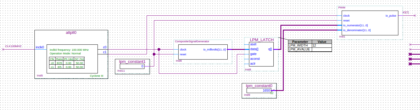
}Now you need to push it into the project Quartus. For Mars Rover 2, we need a free version of Quartus 13.1. How to install it is written on the Mars Rovers website. From there I downloaded the “First Project” for the Mars Rover 2 board, put it in the repository and corrected it a little. Since I am not an electronics engineer (and FPGA actually interests me more as accelerators than as interface boards), then
Сидит программист глубоко в отладке.
Подходит сынишка:
— Папа, почему солнышко каждый день встает на востоке, а садится на западе?
— Ты это проверял?
— Проверял.
— Хорошо проверял?
— Хорошо.
— Работает?
— Работает.
— Каждый день работает?
— Да, каждый день.
— Тогда ради бога, сынок, ничего не трогай, ничего не меняй.
... I just deleted the VGA signal generator and added my own module.
After that, I connected the analog TV tuner to another computer (laptop), so that there was at least some galvanic isolation between the power supply of the generator and the consumer of signals and just gave a signal from the IO7 (+) and GND pins (-) of the motherboard to the composite input (minus on the outer contact, plus - in the center). Well, that is, how "just" ... It would just be if the hands grew from where, well, or if I had female-male connecting wires. But I have only a bunch of male-male wires. But I have an uprightness and nippers! In general, one wire constipation, I still made myself almost two workers - with difficulty, but clinging to the board. And here is what I saw:
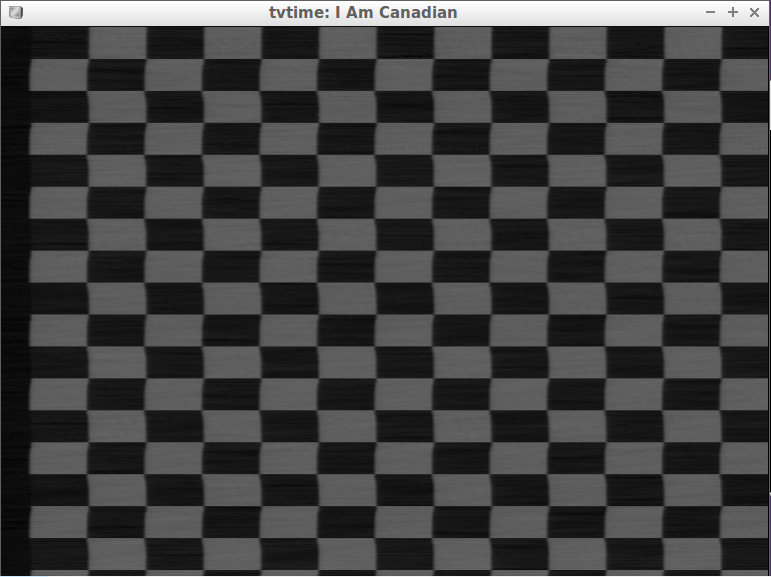
In fact, I, of course, deceived you a little. The code above showed up after about three hours of debugging "on hardware", but, damn, I wrote it, and it works !!! And, considering that I used to be barely familiar with serious electronics, I believe that the task turned out to be no horror, what a difficult one.
Color video generation
Well, that, business remains behind small - to add the generator of color video signal. I took the tutorial and began to try to form a color burst (added to the black level of a sinusoid at the carrier frequency of the color signal, output for a short time during HSync) and, in fact, the color signal by the formula. But it does not come out, even if you are bursting ... At some point it dawned on me that, despite the fact that the frequency didn’t rush into the document with a quick glance at the document, the TV could hardly be adjusted to an arbitrary one. After searching, I found that the PAL uses a carrier frequency of 4.43 MHz. "Case in a hat" - I thought. “Fuck you,” answered the tuner. After a whole day of debugging and only once seeing glimpses of color in the picture (and when I told the tuner that it was NTSC in general)
Then I realized that I could not do without an oscilloscope. And, as I have already said, I am not familiar with electronics, and I, of course, do not have such a miracle of technology. Buy? Expensive for one experiment ... And from what it can be built on the knee? Connect the signal to the line-in sound card? Yeah, 4 and a half megahertz - hardly get started (at least without rework). Hmm, and in fact the Mars Rover has a 20 MHz ADC, but transferring a raw stream of serial interface speed to the computer is not enough. Well, somewhere you still have to process the signal for display on the screen, and in fact there will be quite an acceptable amount of information there, but it’s still messing with the serial port, writing computer programs ... And then I thought that the engineer should develop in a healthy uproticity:
Lyrical digression (as they say, “The student's opinion does not have to coincide with the teacher’s opinion, common sense and Peano’s axiomatics”): When I added color generation with all sorts of multiplications and other complicated things, Fmax for the signal conditioner greatly subsided. What is Fmax? As I understand it from the Harris & Harris textbook, CAD for FPGA prefers when Verilog is not written anyhow as within the standard, but “by concepts”: for example, a synchronous scheme should be obtained - a kind of directed acyclic web of combinational logic(addition, multiplication, division, logical operations, ...), stuck with its inputs and outputs to the outputs and inputs of triggers, respectively. Trigger Edge clock signal stores the entire next cycle the value of its input, which level should be stable as a time to the front and how something - after (this two time se constants). The signals from the outputs of the flip-flops, in turn, after the clock signal begin their run to the outputs of the combinational logic (and therefore, the inputs of other triggers. Well, and the outputs of the chip), which is also characterized by two intervals: the time during which no output has yet will have time to start changing, and the time after which the changes will calm down (provided that the input has changed once). Here is the maximum frequency at which the combinational logic ensures that the requirements of the triggers are met - and that is Fmax. When the circuit between two clocks should be able to count more, Fmax decreases. Of course, I want it to be more, but if it suddenly jumped 10 times (and even the number of frequency domains in the CAD report decreased) - check, maybe you got it wrong somewhere,
Oscilloscope promotion
No, not the one after which there is a twist of the oscilloscope and a handful of unnecessary parts, and the oscilloscope bootstrapping is like a compiler bootstrapping, only for an oscilloscope.
We will do an oscilloscope, recording the number of samples of the input signal at the command, and then only displaying the recorded one. Since he will need to somehow give a command to write, and then to navigate through it, we will need some button controllers - I wrote it is not very convenient, but quite primitive, here it is:
classSimpleButtonController(
      clickThreshold: Int,
      pressThreshold: Int,
      period: Int,
      pressedIsHigh: Boolean) extendsModule{
  val io = IO(newBundle {
    val buttonInput = Input(Bool())
    val click     = Output(Bool())
    val longPress = Output(Bool())
})privateval cycleCounter = RegInit(0.asUInt(32.W))
privateval pressedCounter = RegInit(0.asUInt(32.W))
io.click := false.B
io.longPress := false.B
when (cycleCounter === 0.asUInt) {
when (pressedCounter >= pressThreshold.asUInt) {
io.longPress := true.B
}.elsewhen (pressedCounter >= clickThreshold.asUInt) {
io.click := true.B
}
cycleCounter := period.asUInt
pressedCounter := 0.asUInt
} otherwise {
cycleCounter := cycleCounter - 1.asUInt
when (io.buttonInput === pressedIsHigh.B) {
pressedCounter := pressedCounter + 1.asUInt
}
}
}This is what the oscilloscope will look like:
classOscilloscope(
      clocksPerUs: Int,
      inputWidth: Int,
      windowPixelWidth: Int,
      windowPixelHeight: Int) extendsModule{
  val io = IO(newBundle {
    val signal = Input(UInt(inputWidth.W))
    val visualOffset = Input(UInt(16.W))
    val start = Input(Bool())
    val x = Input(UInt(10.W))
    val y = Input(UInt(10.W))
    val output = Output(Bool())
  })
  privateval mem = SyncReadMem(1 << 15, UInt(inputWidth.W))
  privateval physicalPixel = RegInit(0.asUInt(32.W))
  when (io.start) {
    physicalPixel := 0.asUInt
  }
  when (physicalPixel < mem.length.asUInt) {
    mem.write(physicalPixel, io.signal)
    physicalPixel := physicalPixel + 1.asUInt
  }
  privateval shiftedX = io.x + io.visualOffset
  privateval currentValue = RegInit(0.asUInt(inputWidth.W))
  currentValue :=
    ((1 << inputWidth) - 1).asUInt -
      mem.read(
        Mux(shiftedX < mem.length.asUInt, shiftedX, (mem.length - 1).asUInt)
      )
  when (io.x > windowPixelWidth.asUInt || io.y > windowPixelHeight.asUInt) {
    // Нарисуем 1мс чёрно-белую шкалу
    io.output := !(
      io.y > (windowPixelHeight + 10).asUInt && io.y < (windowPixelHeight + 20).asUInt &&
        (io.x / clocksPerUs.asUInt)(0)
      )
  } otherwise {
    // Нарисуем, собственно, сигнал// signal / 2^inputWidth ~ y / windowPixelHeight// signal * windowPixelHeight ~ y * 2^inputWidth
    io.output :=
      (currentValue * windowPixelHeight.asUInt >= ((io.y - 5.asUInt) << inputWidth).asUInt) &&
      (currentValue * windowPixelHeight.asUInt <= ((io.y + 5.asUInt) << inputWidth).asUInt)
  }
}
And so - the controller that handles keystrokes:
classOscilloscopeController(
      visibleWidth: Int,
      createButtonController: () =>SimpleButtonController
    ) extendsModule {
  val io = IO(newBundle {
    val button1 = Input(Bool())
    val button2 = Input(Bool())
    val visibleOffset = Output(UInt(16.W))
    val start = Output(Bool())
    val leds = Output(UInt(4.W))
  })
  val controller1 = Module(createButtonController())
  val controller2 = Module(createButtonController())
  controller1.io.buttonInput <> io.button1
  controller2.io.buttonInput <> io.button2
  privateval offset = RegInit(0.asUInt(16.W))
  privateval leds = RegInit(0.asUInt(4.W))
  io.start := false.B
  when (controller1.io.longPress && controller2.io.longPress) {
    offset := 0.asUInt
    io.start := true.B
    leds := leds + 1.asUInt
  }.elsewhen (controller1.io.click) {
    offset := offset + (visibleWidth / 10).asUInt
  }.elsewhen (controller2.io.click) {
    offset := offset - (visibleWidth / 10).asUInt
  }.elsewhen (controller1.io.longPress) {
    offset := offset + visibleWidth.asUInt
  }.elsewhen (controller2.io.longPress) {
    offset := offset - visibleWidth.asUInt
  }
  io.visibleOffset := offset
  io.leds := leds
}
In the oscilloscope code, you can look at the example of working with the register file (perhaps not quite correct), but there is something interesting in the controller: in its constructor, the second argument is easy and natural we transfer — no, not the button controller — but the lambda, creating in the required amount of class (in this case - two pieces). It would be necessary - we would give this lambda and arguments! Interestingly, does Verilog do that? ..
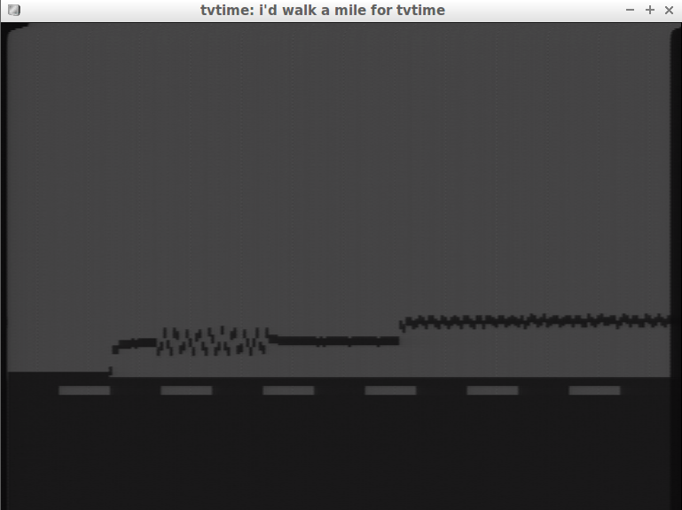
This is how the graph of the initially-digital signal looks like, never leaving the FPGA:
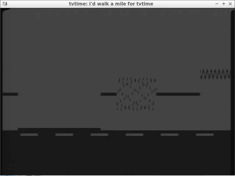
And so - issued (not only from PWM to IO7, but from VGA_GREEN using the R-2R DAC) and digitized back using the Mars Rover's ADC chip:
In general, how long, shortly - and so I tried, and that, but the color did not appear. On Wikipedia, there is even a comic decoding of the abbreviation PAL - "Picture At Last (Finally, a picture!)"
findings
Scala + Chisel form a modern language for describing digital equipment - if expressiveness is required, then with the support of functionalism and all Higher-kinded types. And with the help of the usual Scala-plug-in Idea, who knows nothing about Chisel, it is also very pleasant to program on it. And all this for free and without reference to the CAD of the manufacturer of specific FPGA chips. In general - beauty!
The reader may ask: "And where is the happy ending?" - A NO IT! But there is an oscilloscope ...