We control the stepper motor using the driver
What is a stepper motor?
I will call it below simply “motor”, for short.
I'll tell you briefly, in more detail about him you can read on Wikipedia or here .
The easiest option:
There are four electromagnetic coils A, B, A ', B'. If a current is passed through them, they become magnets (coils A and B are active in the "forward" direction of the current, A 'and B' - in the "reverse" direction).
There is a wheel with teeth (for example, one tooth - arrow).
The clove is attracted to the coil through which current is passed. Thus, if the current in the coils is turned on sequentially, then the arrow will rotate.
To make this movement smoother, you can add cloves, you can reel, or you can both of them - the principle remains the same, only the traction and the angle of rotation change for one on / off.
Usually the following configuration is used: the coils line up four along the perimeter of rotation, for each four there is a tooth, so there is a gear and many coils around it.
Consider the simplest model with four coils and one clove.
Let’s think about how you can rotate the arrow.
Suppose its initial position is at B '.
1. The most obvious:
Turn on A: the arrow stops opposite A.
Turn off A, turn on B: the arrow goes to B and stops opposite.
Turn off B, turn on A ': the arrow stops already at A'.
Turn off A ', turn on B': the arrow goes to B 'and stops opposite.
Turn off B ', turn on A: the arrow stops opposite A., etc.
Each time, a rotation of 90 degrees is made, a full circle, respectively, four times.
Fast, but very sharp.
Than bad:
Sharp, because noisy.
Immediately a large rotation angle, therefore, depending on the load, the inertia can be large, and the accelerated arrow does not stop immediately, so a longer delay is needed before turning off the current coil and turning on the next one.
Because of the problem above, if you make the speed too high, you can lose control over the rotation, and something will fly away somewhere or the movement will become very strange.
Why is it good:relatively easy to implement.
2. A slightly less obvious solution:
Turn on A and B ': the arrow stops between A and B', exactly in the middle.
Turn off B ', turn on B: the arrow is fixed between A and B.
Turn off A, turn on A': the arrow between B and A '.
Turn off B, turn on B ': the arrow stops between A' and B '.
Turn off A ', turn on A: arrow between B' and A. And so on.
At a time - the same 90 degrees, a full circle is also four times.
Too sharply.
What's bad:
Everything is the same as in the previous
Plus method a little more difficult to implement, but not too much.
What is good:
At the same time, two coils are “in force” at once, that is, the traction is much better than that of the previous method.
Accordingly, the threshold speed + inertia, after which we lose control, becomes higher compared to the first method.
3. Grind the steps:
Let us have for each motor not only an on / off state, but a certain state table:
a)
0%
50%
100%
Here 50% means that the current in the coil is 50% of the maximum.
It is possible even smaller:
b)
0%
25%
50%
75%
100%
Or even smaller.
Then the sequence will be like this:
B '100%, A 0%
B' 75%, A 25%
B '50%, A 50%
B' 25%, A 75%
B '0%, A 100%
And the same for steam AB, B-A ', A'-B', B'-B
What's bad:
More difficult to implement.
What is good: The
step is smaller, therefore less noise and rattling, the movement is smoother.
Less problems with inertia and loss of control.
You can make it even smaller, and the movement will be even smoother.
4. We will supply the current in an analog way.
So to say, the limiting case with increasing frequency of partitioning to infinity.
B 'smoothly change from 100% to 0%, A from 0% to 100%, and so for all pairs AB, B-A', A'-B ', B'-B.
What is good:
Very smooth, good control, good traction. And silence.
What is bad:
Analog.
It is patented.
5. We use the following option:
Turn on B 'and A: arrow between B' and A.
Turn off B ': arrow at A.
Turn on B: arrow between A and B.
Turn off A: arrow at B.
Turn on A ': arrow between A' and B.
Turn off B: arrow at A '.
Turn on B ': arrow between B' and A '.
Turn off A ': arrow at B'
Turn on A: arrow between B 'and A.
And so on.
It differs from “0%, 50%, 100%” of step 3 only in draft. 5 is stronger.
Methods 1, 2, 3, 5 are standard, they even have designations.
If we consider the position “near the coil” as 1, and the position “between coils” as 2, the following notation will become clear:
Mode 1 will be called 1 phase (full step) (the arrow stops only at phase “1”), but it is almost not used - traction is bad and in general.
Mode 2: 2 phase (full step) (only on phase “2”).
Mode 5: 1-2 phase (half-step) (stop at “1” and “2”).
Mode 3: Depending on the split frequency:
4 (The cycle from the position “before the coil” to “before the next coil” is four steps): 2W1-2 phase (2 * 2 = 4)
8: 4W1-2 phase (4 * 2 = 8)
In Russian, microstepping.
Mode 3-a is not called, because it is not used, and method 4 is patented.
Thus, the time dependence of the current strength on coils A and B (A 'and B' correspond to negative current values) should be approximately the same (for the case of 1-2 phase).

Driver.
You can, of course, supply a current of the corresponding strength in the desired sequence directly to the motor, or you can use a chip that greatly simplifies control. Such a chip is called a driver. We set the necessary mode settings (in registers), constantly send a timer signal to the driver, and the driver itself generates the output of the desired configuration.
We need: the driver itself (with a motor), a timer of sufficient frequency and a controlling device (processor, microcontroller or fpga).
In general, the driver has pins that are responsible for setting the mode, and control pins.
For example, like this:
The mode itself
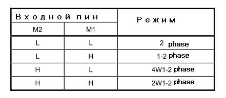
Maximum current (from the maximum according to the specification).

Control pins: timer, direction of rotation (clockwise, counterclockwise), reset pin and enabled pin.

CW - clock-wise
CCW - counter clock-wise
Initial mode - a predefined state of the coils corresponding to the “initial” one. It may be different for different modes. For example, 100% on A and 0% on B for 1-2 phase, 100% on A and -100% on B for 2 phase. By holding the motor in this mode for some time, we guarantee that the motor is turned in a certain manner known in advance. You can start the countdown from this state (we also need to know at what point in time the position of the motor).
Finally, we have a correctly set mode (for example, 1-2 phase) and a working timer. Then the driver output will look like this:
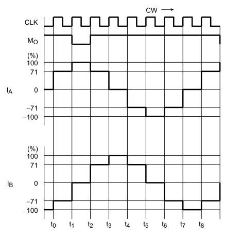
In general, that's all.
For example, the driver from Toshiba TB6560AHQ / AFG was used, although the details are not very important, since the purpose of the article is to tell exactly the general principle, without going into details.
I will call it below simply “motor”, for short.
I'll tell you briefly, in more detail about him you can read on Wikipedia or here .
The easiest option:
There are four electromagnetic coils A, B, A ', B'. If a current is passed through them, they become magnets (coils A and B are active in the "forward" direction of the current, A 'and B' - in the "reverse" direction).
There is a wheel with teeth (for example, one tooth - arrow).
The clove is attracted to the coil through which current is passed. Thus, if the current in the coils is turned on sequentially, then the arrow will rotate.
To make this movement smoother, you can add cloves, you can reel, or you can both of them - the principle remains the same, only the traction and the angle of rotation change for one on / off.
Usually the following configuration is used: the coils line up four along the perimeter of rotation, for each four there is a tooth, so there is a gear and many coils around it.
Consider the simplest model with four coils and one clove.
Let’s think about how you can rotate the arrow.
Suppose its initial position is at B '.
1. The most obvious:
Turn on A: the arrow stops opposite A.
Turn off A, turn on B: the arrow goes to B and stops opposite.
Turn off B, turn on A ': the arrow stops already at A'.
Turn off A ', turn on B': the arrow goes to B 'and stops opposite.
Turn off B ', turn on A: the arrow stops opposite A., etc.
Each time, a rotation of 90 degrees is made, a full circle, respectively, four times.
Fast, but very sharp.
Than bad:
Sharp, because noisy.
Immediately a large rotation angle, therefore, depending on the load, the inertia can be large, and the accelerated arrow does not stop immediately, so a longer delay is needed before turning off the current coil and turning on the next one.
Because of the problem above, if you make the speed too high, you can lose control over the rotation, and something will fly away somewhere or the movement will become very strange.
Why is it good:relatively easy to implement.
2. A slightly less obvious solution:
Turn on A and B ': the arrow stops between A and B', exactly in the middle.
Turn off B ', turn on B: the arrow is fixed between A and B.
Turn off A, turn on A': the arrow between B and A '.
Turn off B, turn on B ': the arrow stops between A' and B '.
Turn off A ', turn on A: arrow between B' and A. And so on.
At a time - the same 90 degrees, a full circle is also four times.
Too sharply.
What's bad:
Everything is the same as in the previous
Plus method a little more difficult to implement, but not too much.
What is good:
At the same time, two coils are “in force” at once, that is, the traction is much better than that of the previous method.
Accordingly, the threshold speed + inertia, after which we lose control, becomes higher compared to the first method.
3. Grind the steps:
Let us have for each motor not only an on / off state, but a certain state table:
a)
0%
50%
100%
Here 50% means that the current in the coil is 50% of the maximum.
It is possible even smaller:
b)
0%
25%
50%
75%
100%
Or even smaller.
Then the sequence will be like this:
B '100%, A 0%
B' 75%, A 25%
B '50%, A 50%
B' 25%, A 75%
B '0%, A 100%
And the same for steam AB, B-A ', A'-B', B'-B
What's bad:
More difficult to implement.
What is good: The
step is smaller, therefore less noise and rattling, the movement is smoother.
Less problems with inertia and loss of control.
You can make it even smaller, and the movement will be even smoother.
4. We will supply the current in an analog way.
So to say, the limiting case with increasing frequency of partitioning to infinity.
B 'smoothly change from 100% to 0%, A from 0% to 100%, and so for all pairs AB, B-A', A'-B ', B'-B.
What is good:
Very smooth, good control, good traction. And silence.
What is bad:
Analog.
It is patented.
5. We use the following option:
Turn on B 'and A: arrow between B' and A.
Turn off B ': arrow at A.
Turn on B: arrow between A and B.
Turn off A: arrow at B.
Turn on A ': arrow between A' and B.
Turn off B: arrow at A '.
Turn on B ': arrow between B' and A '.
Turn off A ': arrow at B'
Turn on A: arrow between B 'and A.
And so on.
It differs from “0%, 50%, 100%” of step 3 only in draft. 5 is stronger.
Methods 1, 2, 3, 5 are standard, they even have designations.
If we consider the position “near the coil” as 1, and the position “between coils” as 2, the following notation will become clear:
Mode 1 will be called 1 phase (full step) (the arrow stops only at phase “1”), but it is almost not used - traction is bad and in general.
Mode 2: 2 phase (full step) (only on phase “2”).
Mode 5: 1-2 phase (half-step) (stop at “1” and “2”).
Mode 3: Depending on the split frequency:
4 (The cycle from the position “before the coil” to “before the next coil” is four steps): 2W1-2 phase (2 * 2 = 4)
8: 4W1-2 phase (4 * 2 = 8)
In Russian, microstepping.
Mode 3-a is not called, because it is not used, and method 4 is patented.
Thus, the time dependence of the current strength on coils A and B (A 'and B' correspond to negative current values) should be approximately the same (for the case of 1-2 phase).
Driver.
You can, of course, supply a current of the corresponding strength in the desired sequence directly to the motor, or you can use a chip that greatly simplifies control. Such a chip is called a driver. We set the necessary mode settings (in registers), constantly send a timer signal to the driver, and the driver itself generates the output of the desired configuration.
We need: the driver itself (with a motor), a timer of sufficient frequency and a controlling device (processor, microcontroller or fpga).
In general, the driver has pins that are responsible for setting the mode, and control pins.
For example, like this:
The mode itself
Maximum current (from the maximum according to the specification).
Control pins: timer, direction of rotation (clockwise, counterclockwise), reset pin and enabled pin.
CW - clock-wise
CCW - counter clock-wise
Initial mode - a predefined state of the coils corresponding to the “initial” one. It may be different for different modes. For example, 100% on A and 0% on B for 1-2 phase, 100% on A and -100% on B for 2 phase. By holding the motor in this mode for some time, we guarantee that the motor is turned in a certain manner known in advance. You can start the countdown from this state (we also need to know at what point in time the position of the motor).
Finally, we have a correctly set mode (for example, 1-2 phase) and a working timer. Then the driver output will look like this:
In general, that's all.
For example, the driver from Toshiba TB6560AHQ / AFG was used, although the details are not very important, since the purpose of the article is to tell exactly the general principle, without going into details.