Your own 3D scanner
- Transfer
My goal was to make a fully functional scanner that can make computer 3d models.
However, I did not want to spend more than $ 20 on all this. True, I did not consider the cost of materials, but anyway it turned out no more than $ 100.

In order to find points in 3D space, there are several ways.
The simplest one is to use 3 numbers to describe the position of one point in relation to another.
This method is used by most computer models.
Another way is to use 3 planes or a plane and a line.
As you can see, the easiest way is to use the third method, and then bring its result to the first.
However, the question arises, how to find the plane and its points?
As it turned out, the first is implemented by hardware, and the second by software.
First, I like to explain the main idea, and then move on to implementation. This will help you find your own solutions.
So, we need to find a plane and somehow record where this plane is, so that the computer can make a model.
Although many people use the edges of the shadow to do this, I decided to go the other way.
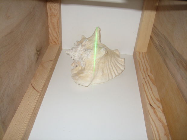
I found a very bright green laser (I can use a laser from a regular laser pointer if you don’t have one).
I directed the laser through a cylindrical lens, which turns it into a line. I used this line to find the plane. This works great, but keep in mind that the size of your scanner will be very limited by the size of the lens: my lens is about a third of an inch in diameter, and I'm limited by the scanned space of about 2 'by 6 "by 6". Smaller lenses will work better, but I don't need this.
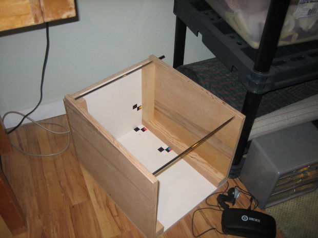
First we need to make a box in which the scanner will be located. The bottom and rear wall of the box are made of melamine, the sides of plywood. After everything was done, I decided that melamine is unnecessary: take the plywood and paint it white. This will save you a few dollars.

The next step is to install and mount the laser.
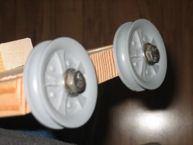
I used an old piece of wood. The rollers are mounted so that the laser rolls along the rails at the top of the window. There, the laser and the lens are mounted so that the plane of light falls perpendicular to the top and bottom of the window.
The camera should be mounted on the side, above the subject. This ensures that the laser line will deflect properly.
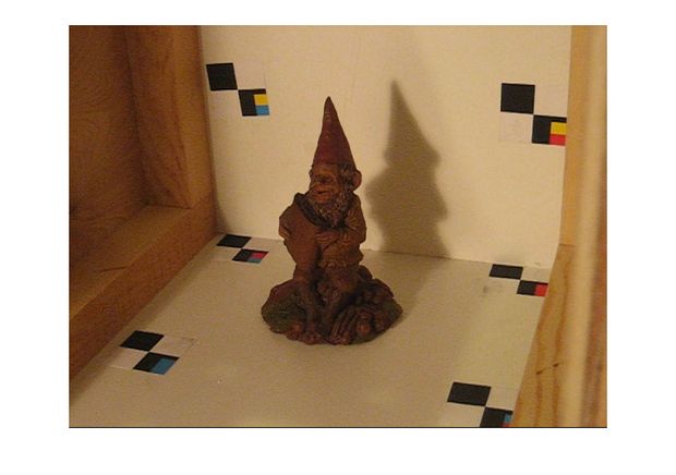
Now you can put some object. I used a gnome. Look at the camera and make sure that the laser deflects noticeably above the subject. Take a look at the photo below to get an idea of what I mean.

The idea behind the software is also pretty simple. There are a number of dots, each of which corresponds to a pixel on the camera. The trick is to learn how to translate points between two spaces. As it turned out, this boils down to a fairly simple equation.
It's time to try our scanner!
Now only one part of the object is scanned - the one that is aimed at the camera. However, you can refine the scanner.
Some more ideas that can be implemented.
From a translator: If you need source codes, then write to the author of the original text.
However, I did not want to spend more than $ 20 on all this. True, I did not consider the cost of materials, but anyway it turned out no more than $ 100.
Training
In order to find points in 3D space, there are several ways.
The simplest one is to use 3 numbers to describe the position of one point in relation to another.
This method is used by most computer models.
Another way is to use 3 planes or a plane and a line.
As you can see, the easiest way is to use the third method, and then bring its result to the first.
However, the question arises, how to find the plane and its points?
As it turned out, the first is implemented by hardware, and the second by software.
Hardware implementation
First, I like to explain the main idea, and then move on to implementation. This will help you find your own solutions.
So, we need to find a plane and somehow record where this plane is, so that the computer can make a model.
Although many people use the edges of the shadow to do this, I decided to go the other way.
I found a very bright green laser (I can use a laser from a regular laser pointer if you don’t have one).
I directed the laser through a cylindrical lens, which turns it into a line. I used this line to find the plane. This works great, but keep in mind that the size of your scanner will be very limited by the size of the lens: my lens is about a third of an inch in diameter, and I'm limited by the scanned space of about 2 'by 6 "by 6". Smaller lenses will work better, but I don't need this.
Housing
First we need to make a box in which the scanner will be located. The bottom and rear wall of the box are made of melamine, the sides of plywood. After everything was done, I decided that melamine is unnecessary: take the plywood and paint it white. This will save you a few dollars.
Laser setting
The next step is to install and mount the laser.
I used an old piece of wood. The rollers are mounted so that the laser rolls along the rails at the top of the window. There, the laser and the lens are mounted so that the plane of light falls perpendicular to the top and bottom of the window.
Camera setup
The camera should be mounted on the side, above the subject. This ensures that the laser line will deflect properly.
Now you can put some object. I used a gnome. Look at the camera and make sure that the laser deflects noticeably above the subject. Take a look at the photo below to get an idea of what I mean.
Software
The idea behind the software is also pretty simple. There are a number of dots, each of which corresponds to a pixel on the camera. The trick is to learn how to translate points between two spaces. As it turned out, this boils down to a fairly simple equation.
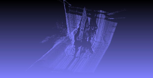
Scanning
It's time to try our scanner!
Now only one part of the object is scanned - the one that is aimed at the camera. However, you can refine the scanner.
Further development
Some more ideas that can be implemented.
- Automation . Matlab may not be the best choice in this case. You can write your own software and add more motors.
- Add a camera rotation . Along with automation, this will allow you to make a complete 3d model.
- Ideally, the software should remove noise.
From a translator: If you need source codes, then write to the author of the original text.