November 9, 2011 at 22:38
The "heart" of an electronic device based on Silicon Labs C8051F320
It happens that you need to quickly develop some kind of electronic device for controlling any units or collecting any information from these units. For this task, either any ready-made devices like Arduino, or a piece of hardware of your own design based on a microcontroller, are ideal. In this article, I decided to consider a small home-made board, which will be the heart of any such device.

The photo shows the resulting device (left) connected to the programmer (right)
So, to create such a piece of hardware, we need a Silicon Labs C8051F320 microcontroller , several SMD resistors and capacitors, a USB cable with a Type A connector, a soldering iron and straight arms.
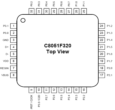
Let's start with the description of the microcontroller. This MK includes a USB controller that allows you to connect it to a PC, as well as power the circuit from USB, if the total consumption does not exceed 400mA, a 10-bit ADC, about 20 input / output ports, an integrated clock generator, as well as a built-in debugger , which makes it easier to debug firmware. The MK has the SMD form factor, the conditional image is shown in the figure:
In order for the MK to be able to work, it must be hung on the board with the necessary elements, connected to power and bring the legs of the I / O ports to the outside of the device. Let's do it this way:
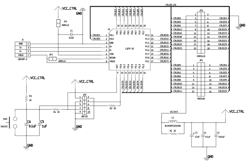
J1 connector - USB type A connector. JP3 jumper switches the device’s power from USB to an external source connected via JP4. For USB power, the JP3 jumper needs to be closed; for power from an external source, open it by closing JP4. Button SW1 carries out a “reset” of the device, i.e. restarts the firmware.
JP2 connector is a programmer connector , through it it performs firmware and debug firmware MK. I / O ports P0 through P2 are routed out through two connectors, JP5 and JP1.
The list of elements used for the scheme:

So, all this must be placed on the circuit board. Since all the elements are on the SMD board, we will place them on both sides of the board to save space. Alas, the wiring of the board itself was lost for me, but this is not a problem, since it can be wired in different ways. Here is what happened in my case.
Conditional image of the board:

As you can see from the image, the scarf turned out to be quite small, which is very convenient - I stuck it in the USB port and that's it, you can work. For convenience, instead of a static USB port soldered to the board, a USB cable was used, cut off from side B and soldered instead of the connector.
Reverse side of the board:

Front side of the board: I

apologize that the USB cable is a little torn off in the photo, the board came out of the box after a month of lying down.
It turned out a suitable working piece of iron, with which you can steer some remote devices from a computer, measure some parameters using the built-in ADC and much more.
The photo shows the resulting device (left) connected to the programmer (right)
So, to create such a piece of hardware, we need a Silicon Labs C8051F320 microcontroller , several SMD resistors and capacitors, a USB cable with a Type A connector, a soldering iron and straight arms.
Let's start with the description of the microcontroller. This MK includes a USB controller that allows you to connect it to a PC, as well as power the circuit from USB, if the total consumption does not exceed 400mA, a 10-bit ADC, about 20 input / output ports, an integrated clock generator, as well as a built-in debugger , which makes it easier to debug firmware. The MK has the SMD form factor, the conditional image is shown in the figure:
In order for the MK to be able to work, it must be hung on the board with the necessary elements, connected to power and bring the legs of the I / O ports to the outside of the device. Let's do it this way:
J1 connector - USB type A connector. JP3 jumper switches the device’s power from USB to an external source connected via JP4. For USB power, the JP3 jumper needs to be closed; for power from an external source, open it by closing JP4. Button SW1 carries out a “reset” of the device, i.e. restarts the firmware.
JP2 connector is a programmer connector , through it it performs firmware and debug firmware MK. I / O ports P0 through P2 are routed out through two connectors, JP5 and JP1.
The list of elements used for the scheme:
So, all this must be placed on the circuit board. Since all the elements are on the SMD board, we will place them on both sides of the board to save space. Alas, the wiring of the board itself was lost for me, but this is not a problem, since it can be wired in different ways. Here is what happened in my case.
Conditional image of the board:
As you can see from the image, the scarf turned out to be quite small, which is very convenient - I stuck it in the USB port and that's it, you can work. For convenience, instead of a static USB port soldered to the board, a USB cable was used, cut off from side B and soldered instead of the connector.
Reverse side of the board:
Front side of the board: I
apologize that the USB cable is a little torn off in the photo, the board came out of the box after a month of lying down.
It turned out a suitable working piece of iron, with which you can steer some remote devices from a computer, measure some parameters using the built-in ADC and much more.