OpenSceneGraph: Procedural animation of geometry and state attributes
- Tutorial

Introduction
Speaking about programming techniques specific to OSG , the last time we talked about the Callback mechanism and its implementation in the engine. It is time to look at the possibilities that this mechanism provides for managing the contents of a three-dimensional scene.
If we talk about object animation, OSG provides the developer with two options for its implementation:
- Procedural animation implemented programmatically through the transformation of objects and their attributes
- Exporting animation from a 3D editor and managing it from application code
To begin, consider the first possibility, as the most obvious. We will definitely talk about the second a bit later.
1. Procedural morphing animation
When traversing the scene graph, OSG transfers data to the OpenGL pipeline, which runs in a separate thread. This thread must be synchronized with other processing threads in each frame. Failure to do so may cause the frame () method to complete before processing geometry data. This will lead to unpredictable program behavior and crashes. OSG offers a solution to this problem in the form of the setDataVariance () method of the osg :: Object class, which is the base for all milestone objects in the scene. You can set three processing modes for objects
- UNSPECIFIED (by default) - OSG independently determines the processing order of the object.
- STATIC - the object is immutable and the order of its processing is not important. Significantly speeds up rendering.
- DYNAMIC - the object must be processed before the start of rendering.
This setting can be set at any time by calling
node->setDataVariance( osg::Object::DYNAMIC );
The generally accepted practice is to modify geometry "on the fly", that is, changing the coordinates of vertices, color normals, and textures dynamically in each frame, obtaining mutable geometry. This technique is called morphing animation. In this case, the order of processing the geometry is decisive - all of its changes must be recalculated before drawing starts. To illustrate this trick, we slightly modify the colored square example, forcing one of its vertices to rotate around the X axis.
Animquad example
main.h
main.cpp
#ifndef		MAIN_H
#define		MAIN_H
#include
#include
#include
#endif
main.cpp
#include	"main.h"
//------------------------------------------------------------------------------
//
//------------------------------------------------------------------------------
osg::Geometry *createQuad()
{
    osg::ref_ptr vertices = new osg::Vec3Array;
    vertices->push_back( osg::Vec3(0.0f, 0.0f, 0.0f) );
    vertices->push_back( osg::Vec3(1.0f, 0.0f, 0.0f) );
    vertices->push_back( osg::Vec3(1.0f, 0.0f, 1.0f) );
    vertices->push_back( osg::Vec3(0.0f, 0.0f, 1.0f) );
    osg::ref_ptr normals = new osg::Vec3Array;
    normals->push_back( osg::Vec3(0.0f, -1.0f, 0.0f) );
    osg::ref_ptr colors = new osg::Vec4Array;
    colors->push_back( osg::Vec4(1.0f, 0.0f, 0.0f, 1.0f) );
    colors->push_back( osg::Vec4(0.0f, 1.0f, 0.0f, 1.0f) );
    colors->push_back( osg::Vec4(0.0f, 0.0f, 1.0f, 1.0f) );
    colors->push_back( osg::Vec4(1.0f, 1.0f, 1.0f, 1.0f) );
    osg::ref_ptr quad = new osg::Geometry;
    quad->setVertexArray(vertices.get());
    quad->setNormalArray(normals.get());
    quad->setNormalBinding(osg::Geometry::BIND_OVERALL);
    quad->setColorArray(colors.get());
    quad->setColorBinding(osg::Geometry::BIND_PER_VERTEX);
    quad->addPrimitiveSet(new osg::DrawArrays(GL_QUADS, 0, 4));
    return quad.release();
}
//------------------------------------------------------------------------------
//
//------------------------------------------------------------------------------
class DynamicQuadCallback : public osg::Drawable::UpdateCallback
{
public:
    virtual void update(osg::NodeVisitor *, osg::Drawable *drawable);
};
//------------------------------------------------------------------------------
//
//------------------------------------------------------------------------------
void DynamicQuadCallback::update(osg::NodeVisitor *, osg::Drawable *drawable)
{
    osg::Geometry *quad = static_cast(drawable);
    if (!quad)
        return;
    osg::Vec3Array *vertices = static_cast(quad->getVertexArray());
    if (!vertices)
        return;
    osg::Quat quat(osg::PI * 0.01, osg::X_AXIS);
    vertices->back() = quat * vertices->back();
    quad->dirtyDisplayList();
    quad->dirtyBound();
}
//------------------------------------------------------------------------------
//
//------------------------------------------------------------------------------
int main(int argc, char *argv[])
{
    (void) argc; (void) argv;
    osg::Geometry *quad = createQuad();
    quad->setDataVariance(osg::Object::DYNAMIC);
    quad->setUpdateCallback(new DynamicQuadCallback);
    osg::ref_ptr root = new osg::Geode;
    root->addDrawable(quad);
    osgViewer::Viewer viewer;
    viewer.setSceneData(root.get());
    return viewer.run();
}
We will create a square in a separate function
osg::Geometry *createQuad()
{
    osg::ref_ptr vertices = new osg::Vec3Array;
    vertices->push_back( osg::Vec3(0.0f, 0.0f, 0.0f) );
    vertices->push_back( osg::Vec3(1.0f, 0.0f, 0.0f) );
    vertices->push_back( osg::Vec3(1.0f, 0.0f, 1.0f) );
    vertices->push_back( osg::Vec3(0.0f, 0.0f, 1.0f) );
    osg::ref_ptr normals = new osg::Vec3Array;
    normals->push_back( osg::Vec3(0.0f, -1.0f, 0.0f) );
    osg::ref_ptr colors = new osg::Vec4Array;
    colors->push_back( osg::Vec4(1.0f, 0.0f, 0.0f, 1.0f) );
    colors->push_back( osg::Vec4(0.0f, 1.0f, 0.0f, 1.0f) );
    colors->push_back( osg::Vec4(0.0f, 0.0f, 1.0f, 1.0f) );
    colors->push_back( osg::Vec4(1.0f, 1.0f, 1.0f, 1.0f) );
    osg::ref_ptr quad = new osg::Geometry;
    quad->setVertexArray(vertices.get());
    quad->setNormalArray(normals.get());
    quad->setNormalBinding(osg::Geometry::BIND_OVERALL);
    quad->setColorArray(colors.get());
    quad->setColorBinding(osg::Geometry::BIND_PER_VERTEX);
    quad->addPrimitiveSet(new osg::DrawArrays(GL_QUADS, 0, 4));
    return quad.release();
}
a description of which, in principle, is not required, since we have done such actions repeatedly. To modify the vertices of this square, we write the DynamicQuadCallback class, inheriting it from osg :: Drawable :: UpdateCallback
class DynamicQuadCallback : public osg::Drawable::UpdateCallback
{
public:
    virtual void update(osg::NodeVisitor *, osg::Drawable *drawable);
};
overriding the update () method in it
void DynamicQuadCallback::update(osg::NodeVisitor *, osg::Drawable *drawable)
{
    osg::Geometry *quad = static_cast(drawable);
    if (!quad)
        return;
    osg::Vec3Array *vertices = static_cast(quad->getVertexArray());
    if (!vertices)
        return;
    osg::Quat quat(osg::PI * 0.01, osg::X_AXIS);
    vertices->back() = quat * vertices->back();
    quad->dirtyDisplayList();
    quad->dirtyBound();
}
Here we get a pointer to a geometry object
osg::Geometry *quad = static_cast(drawable);
we read from the geometry a list of vertices (or rather a pointer to it)
osg::Vec3Array *vertices = static_cast(quad->getVertexArray());
To get the last element (last vertex) in the array, the osg :: Array class provides the back () method. To perform the rotation of the vertex relative to the X axis, we introduce the quaternion
osg::Quat quat(osg::PI * 0.01, osg::X_AXIS);
that is, we set a quaternion that implements a rotation around the X axis by an angle of 0.01 * Pi. Rotate the vertex by multiplying the quaternion by a vector defining the coordinates of the vertex
vertices->back() = quat * vertices->back();
The last two calls recount the display list and the dimensional parallelepiped for the modified geometry
quad->dirtyDisplayList();
quad->dirtyBound();
In the body of the main () function, we create a square, set the dynamic drawing mode for it, and add a callback modifying the geometry
osg::Geometry *quad = createQuad();
quad->setDataVariance(osg::Object::DYNAMIC);
quad->setUpdateCallback(new DynamicQuadCallback);
I will leave indiscriminately creating the root node and launching the viewer, as we have already done this at least twenty times in different ways. As a result, we have the simplest morphing animation
. Now try to remove (comment on) the setDataVariance () call. Perhaps we will not see anything criminal in this case - by default, OSG tries to automatically determine when to update geometry data, trying to synchronize with rendering. Then try changing the mode from DYNAMIC to STATIC and it will be seen that the image does not render smoothly, with noticeable jerks, errors and warnings like this are pouring into the console
Warning: detected OpenGL error 'invalid value' at after RenderBin::draw(..)
If you do not execute the dirtyDisplayList () method, then OpenGL will ignore all changes to the geometry and will use the display list created at the very beginning to create the square for rendering. Delete this call and you will see that there is no animation.
Without calling the dirtyBound () method, the bounding box will not be recalculated and OSG will incorrectly trim invisible faces.
2. The concept of motion interpolation
Suppose that a train going from station A to station B takes 15 minutes to travel. How can we simulate this situation by changing the position of the train in the callback? The easiest way is to correlate the position of station A with time 0, and station B with 15 minutes and move the train evenly between these times. This simplest approach is called linear interpolation. In linear interpolation, a vector specifying the position of an intermediate point is described by the formula
p = (1 - t) * p0 + t * p1
where p0 is the starting point; p1 is the end point; t is a parameter that varies uniformly from 0 to 1. However, the movement of the train is much more complicated: it leaves the station A, accelerates, then moves at a constant speed, and then slows down, stopping at station B. Such a process is no longer able to describe linear interpolation and It looks unnatural.
OSG provides the developer with the osgAnimation library, which contains a number of standard interpolation algorithms used to smoothly animate the movement of scene objects. Each of these functions usually has two arguments: the initial value of the parameter (usually 0) and the final value of the parameter (usually 1). These functions can be applied to the start of the motion (InMotion), to the end of the motion (OutMotion) or to the start and end of the motion (InOutMotion)
| Type of movement | in class | out class | in / out class |
|---|---|---|---|
| Linear interpolation | LinearMotion | - | - |
| Quadratic interpolation | InQuadMotion | OutQuadMotion | InOutQuadMotion |
| Cubic interpolation | InCubicMotion | Outcubicmotion | InOutCubicMotion |
| 4-order interpolation | InQuartMotion | OutQuartMotion | InOutQuartMotion |
| Bounce Effect Interpolation | InBounceMotion | OutBounceMotion | InOutBounceMotion |
| Elastic rebound interpolation | InElasticMotion | OutElasticMotion | InOutElasticMotion |
| Sinusoidal interpolation | InSineMotion | Outsinemotion | InOutSineMotion |
| Inverse Interpolation | Inbackmotion | Outbackmotion | InOutBackMotion |
| Circular interpolation | InCircMotion | Outcircmotion | InOutCircMotion |
| Exponential interpolation | InExpoMotion | Outexpomotion | InOutExpoMotion |
To create a linear interpolation of the movement of an object, we write such a code
osg::ref_ptr motion = new osgAnimation::LinearMotion(0.0f, 1.0f);
3. Animation of transformation nodes
Trajectory animation is the most common type of animation in graphic applications. This technique can be used to animate a car’s movement, an airplane’s flight, or camera’s movement. The trajectory is predefined, with all positions, rotations and scale changes at key points in time. When the simulation cycle starts, the state of the object is recalculated in each frame, using linear interpolation for position and scaling and spherical linear interpolation for quaternions of rotation. To do this, use the slerp () internal method of the osg :: Quat class.
OSG provides the osg :: AnimationPath class to describe a time-varying path. The method of this class insert () is used to add control points corresponding to certain points in time to the trajectory. The control point is described by the osg :: AnimationPath :: ControlPoint class, the constructor of which takes the position as parameters, and, optionally, the object rotation and scaling parameters. for instance
osg::ref_ptr path = new osg::AnimationPath;
path->insert(t1, osg::AnimationPath::ControlPoint(pos1, rot1, scale1));
path->insert(t2, ...);
Here t1, t2 are time instants in seconds; rot1 is the rotation parameter at time t1, described by the osg :: Quat quaternion.
It is possible to control animation loops through the setLoopMode () method. By default, LOOP mode is turned on - the animation will be continuously repeated. Other possible values: NO_LOOPING - play the animation once and SWING - loop the movement in the forward and reverse directions.
After all initializations are completed, we attach the osg :: AnimationPath object to the osg :: AnimationPathCallback built-in object, which is derived from the osg :: NodeCallback class.
4. An example of an animation of movement along a path
Now we will make our cessna move in a circle with the center at the point (0,0,0). The position of the aircraft on the trajectory will be calculated by linearly interpolating the position and orientation between key frames.
Animcessna example
main.h
main.cpp
#ifndef		MAIN_H
#define		MAIN_H
#include
#include
#include
#include
#endif
main.cpp
#include	"main.h"
//------------------------------------------------------------------------------
//
//------------------------------------------------------------------------------
osg::AnimationPath *createAnimationPath(double radius, double time)
{
    osg::ref_ptr path = new osg::AnimationPath;
    path->setLoopMode(osg::AnimationPath::LOOP);
    unsigned int numSamples = 32;
    double delta_yaw = 2.0 * osg::PI / (static_cast(numSamples) - 1.0);
    double delta_time = time / static_cast(numSamples);
    for (unsigned int i = 0; i < numSamples; ++i)
    {
        double yaw = delta_yaw * i;
        osg::Vec3d pos(radius * sin(yaw), radius * cos(yaw), 0.0);
        osg::Quat rot(-yaw, osg::Z_AXIS);
        path->insert(delta_time * i, osg::AnimationPath::ControlPoint(pos, rot));
    }
    return path.release();
}
//------------------------------------------------------------------------------
//
//------------------------------------------------------------------------------
int main(int argc, char *argv[])
{
    (void) argc; (void) argv;
    osg::ref_ptr model = osgDB::readNodeFile("../data/cessna.osg.0,0,90.rot");
    osg::ref_ptr root = new osg::MatrixTransform;
    root->addChild(model.get());
    osg::ref_ptr apcb = new osg::AnimationPathCallback;
    apcb->setAnimationPath(createAnimationPath(50.0, 6.0));
    root->setUpdateCallback(apcb.get());
    osgViewer::Viewer viewer;
    viewer.setSceneData(root.get());
    return viewer.run();
}
We start by creating the trajectory of the aircraft, taking this code into a separate function
osg::AnimationPath *createAnimationPath(double radius, double time)
{
    osg::ref_ptr path = new osg::AnimationPath;
    path->setLoopMode(osg::AnimationPath::LOOP);
    unsigned int numSamples = 32;
    double delta_yaw = 2.0 * osg::PI / (static_cast(numSamples) - 1.0);
    double delta_time = time / static_cast(numSamples);
    for (unsigned int i = 0; i < numSamples; ++i)
    {
        double yaw = delta_yaw * i;
        osg::Vec3d pos(radius * sin(yaw), radius * cos(yaw), 0.0);
        osg::Quat rot(-yaw, osg::Z_AXIS);
        path->insert(delta_time * i, osg::AnimationPath::ControlPoint(pos, rot));
    }
    return path.release();
}
As parameters, the function takes the radius of the circle along which the plane moves and the time during which it will make one revolution. Inside the function, create a trajectory object and turn on the animation looping mode
osg::ref_ptr path = new osg::AnimationPath;
path->setLoopMode(osg::AnimationPath::LOOP);
Following code
unsigned int numSamples = 32;
double delta_yaw = 2.0 * osg::PI / (static_cast(numSamples) - 1.0);
double delta_time = time / static_cast(numSamples);
calculates the approximation parameters of the trajectory. We divide the entire trajectory into numSamples of straight sections, and calculate the change in the angle of rotation of the plane around the vertical axis (yaw) delta_yaw and the change in time delta_time when moving from section to section. Now create the necessary control points
for (unsigned int i = 0; i < numSamples; ++i)
{
    double yaw = delta_yaw * i;
    osg::Vec3d pos(radius * sin(yaw), radius * cos(yaw), 0.0);
    osg::Quat rot(-yaw, osg::Z_AXIS);
    path->insert(delta_time * i, osg::AnimationPath::ControlPoint(pos, rot));
}
In the cycle, all sections of the trajectory from the first to the last are sorted. Each control point is characterized by a yaw angle
double yaw = delta_yaw * i;
the position of the center of mass of the aircraft in space
osg::Vec3d pos(radius * sin(yaw), radius * cos(yaw), 0.0);
The rotation of the aircraft to the desired yaw angle (relative to the vertical axis) is set by the quaternion
osg::Quat rot(-yaw, osg::Z_AXIS);
and then add the calculated parameters to the list of control points of the path
path->insert(delta_time * i, osg::AnimationPath::ControlPoint(pos, rot));
In the main program, we pay attention to the nuance in indicating the name of the aircraft model file at boot time
osg::ref_ptr model = osgDB::readNodeFile("../data/cessna.osg.0,0,90.rot");
- a suffix ".0,0,90.rot" was added to the file name. The mechanism for loading geometry from a file used in OSG allows you to specify the initial position and orientation of the model after loading. In this case, we want the model to be rotated 90 degrees around the Z axis after loading.
Next, the root node is created, which is the transformation node, and the model object is added to it as a child node
osg::ref_ptr root = new osg::MatrixTransform;
root->addChild(model.get());
Now create a trajectory animation callback, adding the path created by the createAnimationPath () function to it
osg::ref_ptr apcb = new osg::AnimationPathCallback;
apcb->setAnimationPath(createAnimationPath(50.0, 6.0));
Attach this callback to the transformation node
root->setUpdateCallback(apcb.get());
The viewer is initialized and launched as usual.
osgViewer::Viewer viewer;
viewer.setSceneData(root.get());
return viewer.run();
We

get an animation of the aircraft. Think, didn’t you find anything strange in this example? Previously, for example, in a program when rendering to a texture, you explicitly changed the transformation matrix to achieve a change in the position of the model in space. Here we just create a transformation node and in the code there is no explicit matrix assignment anywhere.
The secret is that the special osg :: AnimationPathCallback class does this job. In accordance with the current position of the object on the path, it calculates the transformation matrix and automatically applies it to the transformation node to which it is attached, saving the developer from a bunch of routine operations.
It should be noted that attaching osg :: AnimationPathCallback to other types of nodes will not only have no effect, but may also lead to undefined program behavior. It is important to remember that this callback only affects transformation nodes.
5. Software control animation
The osg :: AnimationPathCallback class provides methods for controlling animation during program execution.
- reset () - reset the animation and play it first.
- setPause () - pauses the animation. Takes a boolean value as a parameter
- setTimeOffset () - sets the time offset before the start of the animation.
- setTimeMultiplier () - sets the time factor for acceleration / deceleration of the animation.
For example, to remove the animation from pause and reset, we execute such code
apcb->setPause(false);
apcb->reset();
and to start the animation from the fourth second after starting the program with double acceleration, such a code
apcb->setTimeOffset(4.0f);
apcb->setTimeMultiplier(2.0f);
6. The order of rendering primitives in OpenGL
OpenGL stores vertex and primitive data in various buffers, such as a color buffer, a depth buffer, a stencil buffer, and so on. In addition, he does not overwrite the vertices and triangular faces already sent to his pipeline. This means that OpenGL creates a new geometry, regardless of how the existing geometry was created. This means that the order in which primitives are sent to the rendering pipeline significantly affects the final result that we see on the screen.
Based on the depth buffer data, OpenGL will correctly draw opaque objects, sorting the pixels according to their distance from the observer. However, when using the color mixing technique, for example, when implementing transparent and translucent objects, a special operation will be performed to update the color buffer. The new and old pixels of the image are mixed, taking into account the value of the alpha channel (fourth color component). This leads to the fact that the rendering order of the translucent and opaque edges affects the final result
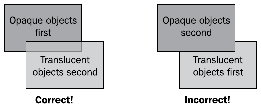
In the figure, in the situation on the left, at first opaque and then transparent objects were sent to the pipeline, which led to the correct shift in the color buffer and the correct display of faces. In the right situation, first transparent objects were drawn, and then opaque, which led to an incorrect display.
The setRenderingHint () method of the osg :: StateSet class indicates to OSG the required rendering order of nodes and geometric objects, if this must be done explicitly. This method simply indicates whether translucent faces should or should not be taken into account when rendering, thereby ensuring that if there are translucent faces in the scene, opaque and then transparent faces will be drawn first, taking into account the distance from the observer. To inform the engine that this node is opaque, we use this code
node->getOrCreateStateSet()->setRenderingHint(osg::StateSet::OPAQUE_BIN);
or contains transparent edges
node->getOrCreateStateSet()->setRenderingHint(osg::StateSet::TRANSPARENT_BIN);
7. An example of the implementation of translucent objects
Let us try to illustrate all the above theoretical introduction with a concrete example of the implementation of a translucent object.
Transparency example
main.h
main.cpp
#ifndef		MAIN_H
#define		MAIN_H
#include
#include
#include
#include
#include
#endif
main.cpp
#include	"main.h"
int main(int argc, char *argv[])
{
    (void) argc; (void) argv;
    osg::ref_ptr vertices = new osg::Vec3Array;
    vertices->push_back( osg::Vec3(-0.5f, 0.0f, -0.5f) );
    vertices->push_back( osg::Vec3( 0.5f, 0.0f, -0.5f) );
    vertices->push_back( osg::Vec3( 0.5f, 0.0f,  0.5f) );
    vertices->push_back( osg::Vec3(-0.5f, 0.0f,  0.5f) );
    osg::ref_ptr normals = new osg::Vec3Array;
    normals->push_back( osg::Vec3(0.0f, -1.0f, 0.0f) );
    osg::ref_ptr texcoords = new osg::Vec2Array;
    texcoords->push_back( osg::Vec2(0.0f, 0.0f) );
    texcoords->push_back( osg::Vec2(0.0f, 1.0f) );
    texcoords->push_back( osg::Vec2(1.0f, 1.0f) );
    texcoords->push_back( osg::Vec2(1.0f, 0.0f) );
    osg::ref_ptr colors = new osg::Vec4Array;
    colors->push_back( osg::Vec4(1.0f, 1.0f, 1.0f, 0.5f) );
    osg::ref_ptr quad = new osg::Geometry;
    quad->setVertexArray(vertices.get());
    quad->setNormalArray(normals.get());
    quad->setNormalBinding(osg::Geometry::BIND_OVERALL);
    quad->setColorArray(colors.get());
    quad->setColorBinding(osg::Geometry::BIND_OVERALL);
    quad->setTexCoordArray(0, texcoords.get());
    quad->addPrimitiveSet(new osg::DrawArrays(GL_QUADS, 0, 4));
    osg::ref_ptr geode = new osg::Geode;
    geode->addDrawable(quad.get());
    osg::ref_ptr texture = new osg::Texture2D;
    osg::ref_ptr image = osgDB::readImageFile("../data/Images/lz.rgb");
    texture->setImage(image.get());
    osg::ref_ptr blendFunc = new osg::BlendFunc;
    blendFunc->setFunction(GL_SRC_ALPHA, GL_ONE_MINUS_SRC_ALPHA);
    osg::StateSet *stateset = geode->getOrCreateStateSet();
    stateset->setTextureAttributeAndModes(0, texture.get());
    stateset->setAttributeAndModes(blendFunc);
    osg::ref_ptr root = new osg::Group;
    root->addChild(geode.get());
    root->addChild(osgDB::readNodeFile("../data/glider.osg"));
    osgViewer::Viewer viewer;
    viewer.setSceneData(root.get());
    return viewer.run();
}
For the most part, the code shown here does not contain anything new: two geometric objects are created - a textured square and a hang glider, the model of which is loaded from a file. However, we apply a white translucent color to all the vertices of the square
colors->push_back( osg::Vec4(1.0f, 1.0f, 1.0f, 0.5f) );
- the alpha channel value is 0.5, which, when mixed with texture colors, should give the effect of a translucent object. In addition, the color blending function should be set for transparency processing.
osg::ref_ptr blendFunc = new osg::BlendFunc;
blendFunc->setFunction(GL_SRC_ALPHA, GL_ONE_MINUS_SRC_ALPHA);
passing it to the OpenGL state machine
stateset->setAttributeAndModes(blendFunc);
When compiling and running this program, we get the following result

Stop! And where is the transparency? The thing is that we forgot to tell the engine that transparent edges should be processed, which is easily solved by calling
stateset->setRenderingHint(osg::StateSet::TRANSPARENT_BIN);
after which we will get the result we need - the glider wing shines through a translucent textured square

The parameters of the mixing function GL_SRC_ALPHA and GL_ONE_MINUS_SRC_ALPHA mean that the resulting screen pixel when drawing a translucent face will have color components calculated by the formula
R = srcR * srcA + dstR * (1 - srcA)
G = srcG * srcA + dstG * (1 - srcA)
B = srcB * srcA + dstB * (1 - srcA)
where [srcR, srcG, srcB] are the color components of the square texture; [dstR, dstG, dstB] - color components of each pixel of the area on which a translucent face is superimposed, given that the background and the opaque edges of the glider wing are already drawn at this place. By srcA I mean the alpha component of the color of the square.
The seRenderingHint () method perfectly arranges the rendering of primitives, but using it is not very efficient, since sorting transparent objects by depth when rendering a frame is quite a resource-intensive operation. Therefore, the developer should take care of the order of drawing the faces on their own, if possible at the preliminary stages of scene preparation.
8. Animation of state attributes
Using animation, you can also control state attributes. A whole host of visual effects can be generated by changing the properties of one or more rendering attributes. This kind of animation that changes the state of rendering attributes is easy to implement through the callback mechanism when updating the scene.
Classes of standard interpolations can also be used to specify the function of changing attribute parameters.
We already have experience in creating translucent objects. We know that if the alpha component of the color is zero, we get a completely transparent object, with a value of 1 - completely opaque. It is clear that by varying this parameter from 0 to 1 in time, the effect of the gradual appearance or disappearance of an object can be obtained. We illustrate this with a concrete example.
Fading-in example
main.h
main.cpp
#ifndef		MAIN_H
#define		MAIN_H
#include
#include
#include
#include
#include
#include
#include
#endif
main.cpp
#include	"main.h"
//------------------------------------------------------------------------------
//
//------------------------------------------------------------------------------
class AlphaFadingCallback : public osg::StateAttributeCallback
{
public:
    AlphaFadingCallback()
    {
        _motion = new osgAnimation::InOutCubicMotion(0.0f, 1.0f);
    }
    virtual void operator() (osg::StateAttribute* , osg::NodeVisitor*);
protected:
    osg::ref_ptr _motion;
};
//------------------------------------------------------------------------------
//
//------------------------------------------------------------------------------
void AlphaFadingCallback::operator()(osg::StateAttribute *sa, osg::NodeVisitor *nv)
{
    (void) nv;
    osg::Material *material = static_cast(sa);
    if (material)
    {
        _motion->update(0.0005f);
        float alpha = _motion->getValue();
        material->setDiffuse(osg::Material::FRONT_AND_BACK, osg::Vec4(0.0f, 1.0f, 1.0f, alpha));
    }
}
//------------------------------------------------------------------------------
//
//------------------------------------------------------------------------------
int main(int argc, char *argv[])
{
    (void) argc; (void) argv;
    osg::ref_ptr quad = osg::createTexturedQuadGeometry(
                osg::Vec3(-0.5f, 0.0f, -0.5f),
                osg::Vec3(1.0f, 0.0f, 0.0f),
                osg::Vec3(0.0f, 0.0f, 1.0f));
    osg::ref_ptr geode = new osg::Geode;
    geode->addDrawable(quad.get());
    osg::ref_ptr material = new osg::Material;
    material->setAmbient(osg::Material::FRONT_AND_BACK, osg::Vec4(0.0f, 0.0f, 0.0f, 1.0f));
    material->setDiffuse(osg::Material::FRONT_AND_BACK, osg::Vec4(0.0f, 1.0f, 1.0f, 0.5f));
    material->setUpdateCallback(new AlphaFadingCallback);
    geode->getOrCreateStateSet()->setAttributeAndModes(material.get());
    geode->getOrCreateStateSet()->setAttributeAndModes(new osg::BlendFunc(GL_SRC_ALPHA, GL_ONE_MINUS_SRC_ALPHA));
    geode->getOrCreateStateSet()->setRenderingHint(osg::StateSet::TRANSPARENT_BIN);
    osg::ref_ptr root = new osg::Group;
    root->addChild(geode.get());
    root->addChild(osgDB::readNodeFile("../data/glider.osg"));
    osgViewer::Viewer viewer;
    viewer.setSceneData(root.get());
    return viewer.run();
}
We start by creating a callback handler for changing the value of the alpha channel over time
class AlphaFadingCallback : public osg::StateAttributeCallback
{
public:
    AlphaFadingCallback()
    {
        _motion = new osgAnimation::InOutCubicMotion(0.0f, 1.0f);
    }
    virtual void operator() (osg::StateAttribute* , osg::NodeVisitor*);
protected:
    osg::ref_ptr _motion;
};
The protected parameter _motion will determine the function by which the alpha value will change over time. For this example, we choose the cubic spline approximation, setting it immediately, in the class constructor
AlphaFadingCallback()
{
    _motion = new osgAnimation::InOutCubicMotion(0.0f, 1.0f);
}
This dependence can be illustrated by such a curve.

In the constructor of the InOutCubicMotion object, we determine the limits of the approximated value from 0 to 1. Next, we redefine operator () for this class in this way
void AlphaFadingCallback::operator()(osg::StateAttribute *sa, osg::NodeVisitor *nv)
{
    (void) nv;
    osg::Material *material = static_cast(sa);
    if (material)
    {
        _motion->update(0.0005f);
        float alpha = _motion->getValue();
        material->setDiffuse(osg::Material::FRONT_AND_BACK, osg::Vec4(0.0f, 1.0f, 1.0f, alpha));
    }
}
Get a pointer to the material
osg::Material *material = static_cast(sa);
The abstract value of the attribute comes to callback, however we will attach this handler to the material, therefore it is the pointer to the material that will come, therefore we can safely convert the state attribute to the pointer to the material. Next, we set the update interval of the approximating function - the larger it is, the faster the parameter will change within the specified range
_motion->update(0.0005f);
We read the value of the approximating function
float alpha = _motion->getValue();
and give the material a new diffuse color value
material->setDiffuse(osg::Material::FRONT_AND_BACK, osg::Vec4(0.0f, 1.0f, 1.0f, alpha));
Now let's form the scene in the main () function. I think you are tired every time to build a square on the vertices, so we simplify the task - we generate a square polygon with the standard OSG function
osg::ref_ptr quad = osg::createTexturedQuadGeometry(
                osg::Vec3(-0.5f, 0.0f, -0.5f),
                osg::Vec3(1.0f, 0.0f, 0.0f),
                osg::Vec3(0.0f, 0.0f, 1.0f));
The first parameter is the point from which the lower left corner of the square will be built, the other two parameters specify the coordinates of the diagonals. Having figured out the square, we create material for it
osg::ref_ptr material = new osg::Material;
material->setAmbient(osg::Material::FRONT_AND_BACK, osg::Vec4(0.0f, 0.0f, 0.0f, 1.0f));
material->setDiffuse(osg::Material::FRONT_AND_BACK, osg::Vec4(0.0f, 1.0f, 1.0f, 0.5f));
We indicate the color options of the material. Ambient color is a parameter that characterizes the color of the material in the shaded area, inaccessible to color sources. Diffuse color is the material’s own color, which characterizes the ability of a surface to dissipate the color falling on it, that is, what we are used to call color in everyday life. The FRONT_AND_BACK parameter indicates that this color attribute is assigned to both the front and back sides of the geometry faces.
Assign material to the previously created handler.
material->setUpdateCallback(new AlphaFadingCallback);
Assign the created material to the square
geode->getOrCreateStateSet()->setAttributeAndModes(material.get());
and set other attributes - the function of mixing colors and indicate that this object has transparent edges
geode->getOrCreateStateSet()->setAttributeAndModes(new osg::BlendFunc(GL_SRC_ALPHA, GL_ONE_MINUS_SRC_ALPHA));
geode->getOrCreateStateSet()->setRenderingHint(osg::StateSet::TRANSPARENT_BIN);
We complete the formation of the scene and run the viewer
osg::ref_ptr root = new osg::Group;
root->addChild(geode.get());
root->addChild(osgDB::readNodeFile("../data/glider.osg"));
osgViewer::Viewer viewer;
viewer.setSceneData(root.get());
return viewer.run();
We get the result in the form of a square smoothly appearing in the scene

Instead of a conclusion: a small remark about dependencies
Surely your example does not compile, giving an error at the build stage. This is no coincidence - pay attention to the line in the header file main.h
#include The OSG header directory from which the header file is taken usually points to the library that contains the implementation of the functions and classes described in the header. Therefore, the appearance of the osgAnimation / directory should suggest that a library of the same name should be added to the link list of the project build script, something like this (taking into account the paths to libraries and the build version)
LIBS += -losgAnimation
To be continued...