January 25, 2011 at 11:02
Give me the iron! Part 2
Part 1
So, we have purchased everything you need. It is time to set up an experimental laboratory!
We put the software that comes with the programmer: PICKit2 Utility and MPLAB IDE. The first is a utility for working with the programmer, the second is a development environment. We basically do not need PICKit2 Utility, but there is one point that I will mention later. In the meantime, we turn our attention to the MPLAB IDE.
MPLAB IDE
We open the development environment and create a new project. One of the disadvantages of this IDE is the lack of sticky panels, instead we have a heap of windows. In order to be able to live on, I arranged everything in the usual way (the window was reduced to fit the picture):
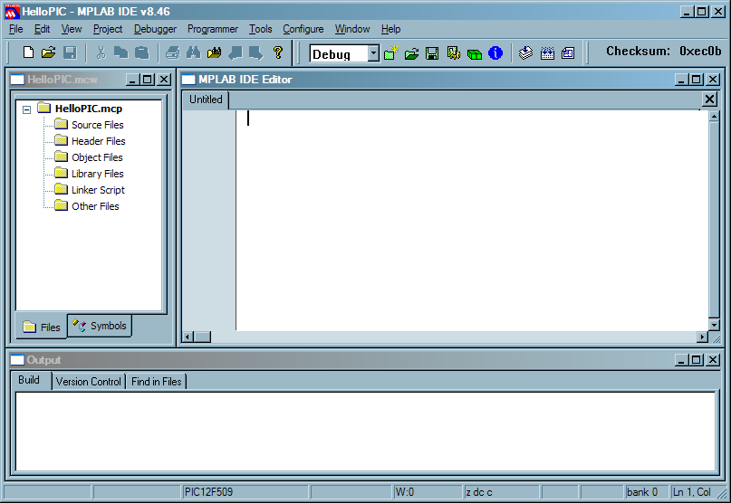
upd: everything sticks perfectly! Click on the icon in the upper left corner of the window, select Dockable in the menu, and then drag it to the border. Thanks lunatik42 for the info!
File> New ; File> Save as ... , select the type Assembly, check the Add to project checkbox. So yes, we will code in assembler.
You also need to tell the IDE that we are using assembler.
We climb into Project> Select Language Toolsuite ... and select Microchip MPASM Toolsuite:
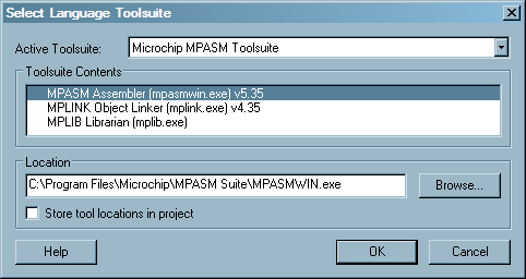
Now go to Project> Build options ...> Project , we have compilation settings there. On the tab “MPASM / C17 / C18 Suite” we select the generation of the absolute code:

When writing the absolute code, we ourselves can specify what addresses our code and data should be located at. When writing portable code, the compiler drives the memory itself, but for this we have to steam with sections, we don’t need it yet.
On the MPLAB Assembler tab, you can disable case sensitivity of variables. I decided not to disconnect.
Well, to make things easier, we crawl in Edit> Properties ... There we put the display of line numbers and change the font to taste. I put a skittle in the Lucida Console 8 so that more code would fit into the window.
Again materiel
Our current task is to write the minimum amount of code that will compile in order to try to flash the controller. As a result, we get a few lines of code, but to write them you will have to read a lot of documentation. We will need two sources: datasheets and built-in IDE manuals ( Help> Topics ...> MPLAB Assembler ), which open in a separate window and do not interfere with the process. There is a table with a set of commands and a description of all directives; if you come across an incomprehensible word in the code, then for the interpretation you need to climb there.
The “8.0 Instruction Set Summary” section of the datasheet provides a detailed description of the command system, I recommend that you read this section carefully.
Minimum code
Okay, you can finally get around a bit - we can!
Let's start from the end and write a single line:
end
We compile on F10, we get a successful build and an error, they say it is impossible to download something there. We also get vorning from the compiler, which does not like the directives at the beginning of the line - this is not a problem, we shift our end by one tab. As for the error, its cause is the lack of stone configuration. The config is essentially a 12-bit word that is written to the stone during firmware, for AVR stones this is called fuse-bits. The meaning of each bit is described in the datasheet, section “7.1 Configuration Bits”.
And now the quest for attentiveness! What did we forget to do? We forgot to indicate under which stone we need to collect our code. To do this, go to Configure> Select Device ... and select our stone - PIC12F509. The IDE boasts a bunch of opportunities that it provides for this stone:
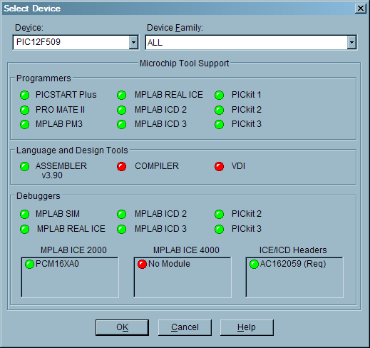
But what if we suddenly want to use a different development environment? To do this, we can specify the type of stone directly in the code, this is done using the list directive. After reading the manuals on this directive, it becomes clear that you need to write the following (do not forget about the tab at the beginning):
list p = 12f509
The type of stone specified in the settings is passed to the compiler via the command line, and it takes precedence over the list directive. Therefore, if you set one stone in the settings, and write another in the directive, the code will compile to the stone specified in the settings, and the compiler will give out the processor Process superseded by command line. Verify processor symbol. "
We indicated the stone. Now we recall that in the section of the datasheet “4.3 Data Memory Organization” it is written that the registers of our stone lie in the address space of the data memory. To access them by name, not address, we include the header file:
#include p12f509.inc
Кроме адресов регистров, там прописаны номера конфигурационных битов — то, что нам сейчас понадобится. Также этот файл можно добавить в проект, чтобы видеть все определенные им константы в списке символов.
Вот теперь мы можем задать конфигурацию. Ее можно указать в Configure > Configuration bits..., но для лучшей переносимости и более удобного доступа лучше сделать это прямо в коде, для чего нам поможет директива __config. Открываем наш инклуд и смотрим секцию «Configuration bits». Биты названы в соответствии с даташитом.
Нам нужна следующая конфигурация: MCLR отключен (работает как обычный пин), защита кода отключена, сторожевой таймер отключен, для тактирования используется внутренний генератор. Таким образом, наш конфиг примет следующий вид:
__config _IntRC_OSC & _CP_OFF & _WDT_OFF & _MCLRE_OFF
Please note that the values are combined using the "AND". At first, out of habit, I wrote everything through OR, and then I wondered for a long time why nothing was working.
So, here is what we ended up with:
list p = 12f509 #include p12f509.inc __config _IntRC_OSC & _CP_OFF & _WDT_OFF & _MCLRE_OFF end
We compile ... successfully! As I promised, a few lines and a lot of documentation.
Take iron
So the moment has come that you have been waiting for so long! If you scrolled the page in search of the place where the story finally reaches the iron, then it's time to stop and start reading :)
So, we have a programmer, microcontroller, program and unhealthy enthusiasm to combine all this. And now we are only tormented by one question: what to connect with?
We climb into the datasheet, section 7.12 “In-Circuit Serial Programming” and see this picture:
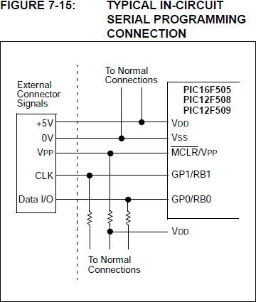
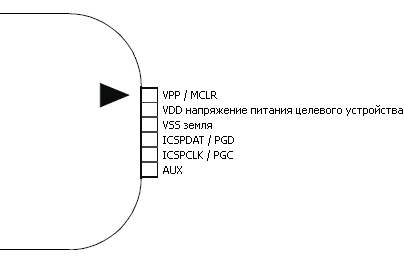
We do not have Normal Connections so far, so we look only at the connection of the legs of the programmer with the legs of the stone. Okay, what we connected with, we now need to find where these pins grow from on the stone and on the programmer.
From the manuals to the programmer we learn the purpose of its conclusions:
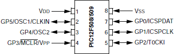
In the datasheet (section "Pin Diagrams") we see the conclusions of the microcontroller:
Now we look at the stone.
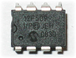
Perplexed. Well, and on what corner is his first conclusion? Where is the top and where is the bottom? To understand this, we climb into Wikipedia and read about the DIP package . From there we find out that the conclusions are numbered counterclockwise from a semicircular notch:
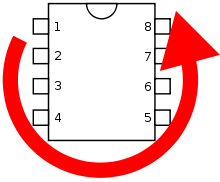
It turns out that the caring guys from Microchip even put a dot for us near the first output.
We finally get the breadboard! I connected everything as follows:
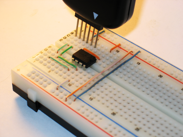
The same thing in augmented reality, as the rule very accurately put it :

Flashing
We are just a few clicks from the long-awaited result! So, we connect our programmer, if it is not already connected, then in MPLAB we climb into the Programmer menu and select our programmer there - PICKit2. The programmer messages tab opens in the output window, where he cheerfully reports on his readiness. And also we will have such a panel for controlling the programmer:

We need the leftmost button - “Program the target device”. Push!
If we did everything right, then a progress bar will run below, and messages about mashing and recording program memory will appear in the output window. Congratulations, the stone is stitched! :)
In the next part we will write HelloWorld, and I will also tell you why we still need PICKit2 Utility. See you!
The end of the second part.
Part 1