We write our OS: Issue 2
Hello. This is again we, iley and pehat , with the long-awaited second article from the series “Writing Your Own OS” (first article here ). We apologize for the big pause after the first article, it took us some time to determine the future direction of our work. In this issue, we briefly review the protected mode of 32-bit Intel processors. We emphasize once again that we do not set ourselves the goal of providing comprehensive theoretical data.
Let's remember for a moment our program from the previous release. It started instead of the operating system and displayed the message “Hello world”. The program was written in 16-bit assembler and worked in the so-called real mode. As you probably know, when addressing in real mode, a physical address is formed using a segment and an offset and has a dimension of 20 bits. Simple mathematics tells us that in this way you can access only a megabyte of RAM.
The small amount of available memory is not the only problem in real mode. Imagine a situation where the memory simultaneously contains the operating system and several application programs. In real mode, nothing prevents any of the application programs from contacting an address belonging to another program or even the operating system. Thus, an error in one program can lead to the collapse of the entire system.
To solve these two problems, Intel at one time developed a new, much more complex way of addressing RAM. More precisely, Intel even developed several addressing methods, and all of them are known collectively as protected mode .
So, addressing in protected mode can occur in one of three modes (sorry for the tautology) - in segment, page and segment-page. In this issue, we will only consider segmented mode.
In segmented modestrangely enough, segments are allocated in memory. These segments are significantly different from simple and familiar segments of the real mode. In this case, a segment is a continuous area of memory, which is characterized by a base, limit (i.e., roughly speaking, size) and some additional attributes. The base is, roughly speaking, the physical address from which the segment begins (in fact, this is not a physical address, but the so-called linear one, but more on that later). It is important to note that, unlike real-mode segments, our segments can be of arbitrary size. The base, size and attributes of each segment are stored in a descriptor . Descriptors are stored in special tables, and selectors are used to select a specific descriptor from the table. Do not be alarmed by such a bunch of new scary words, we will now sort things out.
So, each time the memory is accessed, the processor takes from the register (for example, CS), the selector, finds the descriptor in the table from it, extracts the address of the beginning of the segment from the descriptor, adds the offset to the start address and gets the linear address (note that the linear address and the physical address is two different things, but at this stage we can assume that this is one and the same). In addition, the processor checks to see if the received address has gone beyond the segment boundary and whether segment attributes currently allow access to it. The linear address calculation scheme looks something like this:

So, as we already said, the base (base address), size (segment limit) and any additional segment attributes are stored in the descriptor. Let's take a look at the descriptor schema.
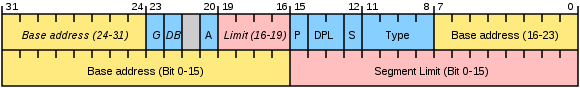
Please note that 32 bits are allocated for the base, and only 20 for the limit. How can it be, you ask, is it really impossible to create a segment larger than a megabyte? Can. For this, a simple trick is used. If bit G is set to one, then the limit is considered not in bytes, but in blocks of 4 Kbytes. It should be noted that the limit contains the segment size minus one in units of granularity, i.e. if the limit is 0, then the segment is 1 byte or 4 KB in size. In addition, as you can see, the handle includes a few more fields. A detailed description of them can be found, for example, here .
As mentioned, descriptors are stored in special tables. There can be several tables, but in any case, GDT , the global descriptor table, must be present in memory . She is one for the entire operating system. In turn, each task, that is, a process, can have zero, one or more LDT - local descriptor tables. The address and size of the GDT is stored in the GDTR register , the current LDT is in the LDTR register . While we do not need LDT. In addition, there are also IDT tables of interrupt descriptors, but we will postpone their consideration until the next release.
A data structure called a selector is used to select a descriptor from the table. Here's what it looks like:

The selector contains a bit indicating in which table to search for the descriptor, local or global (L / G) and the descriptor number itself. In addition, the selector has an RPL field, but it does not interest us yet.
So let's get down to business!
Now let's explain the code a bit.
In the lines:
The address line A20 is unlocked. What does it mean? Recall that in real mode you can address 1 MB of memory in the format
After loading the address and limit of the global descriptor table into the GDTR register, there is a universal ban on interrupts. This is explained by the fact that all interrupt handlers work in real mode, and in protected mode addressing problems will begin. So for now we strictly forbid interrupts.
The inclusion of protected mode is carried out by setting the least significant bit of the register
Here, the prefix of the conversion of the bit width of the operand is used
To run the program, you need to do the manipulations that completely coincide with those described in the first article . There you will find a list of references in case you want to know more about protected mode.
We didn’t have enough imagination for something demonstrating the real possibilities of the protected mode, therefore we again display “Hello, World!”, But already using direct access to video memory. To make something beautiful, it would be convenient to use interrupts. The next article in our series will be devoted to how to use them in protected mode. And the second article ends there. We will be glad to see your feedback and suggestions.
Let's remember for a moment our program from the previous release. It started instead of the operating system and displayed the message “Hello world”. The program was written in 16-bit assembler and worked in the so-called real mode. As you probably know, when addressing in real mode, a physical address is formed using a segment and an offset and has a dimension of 20 bits. Simple mathematics tells us that in this way you can access only a megabyte of RAM.
The small amount of available memory is not the only problem in real mode. Imagine a situation where the memory simultaneously contains the operating system and several application programs. In real mode, nothing prevents any of the application programs from contacting an address belonging to another program or even the operating system. Thus, an error in one program can lead to the collapse of the entire system.
To solve these two problems, Intel at one time developed a new, much more complex way of addressing RAM. More precisely, Intel even developed several addressing methods, and all of them are known collectively as protected mode .
So, addressing in protected mode can occur in one of three modes (sorry for the tautology) - in segment, page and segment-page. In this issue, we will only consider segmented mode.
In segmented modestrangely enough, segments are allocated in memory. These segments are significantly different from simple and familiar segments of the real mode. In this case, a segment is a continuous area of memory, which is characterized by a base, limit (i.e., roughly speaking, size) and some additional attributes. The base is, roughly speaking, the physical address from which the segment begins (in fact, this is not a physical address, but the so-called linear one, but more on that later). It is important to note that, unlike real-mode segments, our segments can be of arbitrary size. The base, size and attributes of each segment are stored in a descriptor . Descriptors are stored in special tables, and selectors are used to select a specific descriptor from the table. Do not be alarmed by such a bunch of new scary words, we will now sort things out.
So, each time the memory is accessed, the processor takes from the register (for example, CS), the selector, finds the descriptor in the table from it, extracts the address of the beginning of the segment from the descriptor, adds the offset to the start address and gets the linear address (note that the linear address and the physical address is two different things, but at this stage we can assume that this is one and the same). In addition, the processor checks to see if the received address has gone beyond the segment boundary and whether segment attributes currently allow access to it. The linear address calculation scheme looks something like this:
So, as we already said, the base (base address), size (segment limit) and any additional segment attributes are stored in the descriptor. Let's take a look at the descriptor schema.
Please note that 32 bits are allocated for the base, and only 20 for the limit. How can it be, you ask, is it really impossible to create a segment larger than a megabyte? Can. For this, a simple trick is used. If bit G is set to one, then the limit is considered not in bytes, but in blocks of 4 Kbytes. It should be noted that the limit contains the segment size minus one in units of granularity, i.e. if the limit is 0, then the segment is 1 byte or 4 KB in size. In addition, as you can see, the handle includes a few more fields. A detailed description of them can be found, for example, here .
As mentioned, descriptors are stored in special tables. There can be several tables, but in any case, GDT , the global descriptor table, must be present in memory . She is one for the entire operating system. In turn, each task, that is, a process, can have zero, one or more LDT - local descriptor tables. The address and size of the GDT is stored in the GDTR register , the current LDT is in the LDTR register . While we do not need LDT. In addition, there are also IDT tables of interrupt descriptors, but we will postpone their consideration until the next release.
A data structure called a selector is used to select a descriptor from the table. Here's what it looks like:
The selector contains a bit indicating in which table to search for the descriptor, local or global (L / G) and the descriptor number itself. In addition, the selector has an RPL field, but it does not interest us yet.
So let's get down to business!
;16-битная адресация, пока мы находимся в реальном режиме

use16

org 0x7c00

start:

  jmp 0x0000:entry              ;теперь CS=0, IP=0x7c00

entry:

  mov ax, cs

  mov ds, ax


;очистить экран

  mov ax, 0x0003

  int 0x10


;открыть A20

  in  al, 0x92

  or  al, 2

  out 0x92, al


;Загрузить адрес и размер GDT в GDTR

  lgdt  [gdtr]

;Запретить прерывания

  cli

;Запретить немаскируемые прерывания

  in  al, 0x70

  or  al, 0x80

  out 0x70, al


;Переключиться в защищенный режим

  mov  eax, cr0

  or   al, 1

  mov  cr0, eax


;Загрузить в CS:EIP точку входа в защищенный режим

  O32 jmp 00001000b:pm_entry


;32-битная адресация

use32

;Точка входа в защищенный режим

pm_entry:

;Загрузить сегментные регистры (кроме SS)

  mov  ax, cs

  mov  ds, ax

  mov  es, ax


  mov  edi, 0xB8000             ;начало видеопамяти в видеорежиме 0x3

  mov  esi, msg                 ;выводимое сообщение

  cld

.loop                           ;цикл вывода сообщения

  lodsb                         ;считываем очередной символ строки

  test al, al                   ;если встретили 0

  jz   .exit                    ;прекращаем вывод

  stosb                         ;иначе выводим очередной символ

  mov  al, 7                    ;и его атрибут в видеопамять

  stosb

  jmp  .loop

.exit


  jmp  $                        ;зависаем


msg:

  db  'Hello World!', 0


;Глобальная таблица дескрипторов.

;Нулевой дескриптор использовать нельзя!

gdt:

  db  0x00, 0x00, 0x00, 0x00, 0x00,      0x00,      0x00, 0x00

  db  0xFF, 0xFF, 0x00, 0x00, 0x00, 10011010b, 11001111b, 0x00

gdt_size  equ $ - gdt


;данные, загружаемые в регистр GDTR

gdtr:

  dw  gdt_size - 1

  dd  gdt


finish:

 times 0x1FE-finish+start db 0

 db   0x55, 0xAA ; сигнатура загрузочного сектора
Now let's explain the code a bit.
In the lines:
in al, 0x92


or al, 2


out 0x92, al
The address line A20 is unlocked. What does it mean? Recall that in real mode you can address 1 MB of memory in the format
сегмент:смещение(20 bits per address). However, by contacting, for example, the address FFFF:FFFF, you can “jump” a little higher than this bar, and the received address will have a length of 21 bits. In processors up to 80286, the oldest (twentieth, if you count from zero) was discarded, and therefore, for compatibility with older programs, an A20 address line lock was introduced. Currently, all operating systems operate in protected mode, and therefore, for the needs of addressing, it is necessary to unlock this bit as soon as possible. So it goes.After loading the address and limit of the global descriptor table into the GDTR register, there is a universal ban on interrupts. This is explained by the fact that all interrupt handlers work in real mode, and in protected mode addressing problems will begin. So for now we strictly forbid interrupts.
The inclusion of protected mode is carried out by setting the least significant bit of the register
CR0. Immediately after the transition to protected mode, a certain uncertainty arises: CS:EIPyou need to set the entry point to the protected mode in the format селектор:смещение, but we still have vestiges of the real mode there. Therefore, we execute the following instruction:O32 jmp 00001000b:pm_entryHere, the prefix of the conversion of the bit width of the operand is used
O32, which allows you to make a long unconditional jump with a 32-bit offset. Hooray, we can finally take advantage of the charms of the protected regime! To run the program, you need to do the manipulations that completely coincide with those described in the first article . There you will find a list of references in case you want to know more about protected mode.
We didn’t have enough imagination for something demonstrating the real possibilities of the protected mode, therefore we again display “Hello, World!”, But already using direct access to video memory. To make something beautiful, it would be convenient to use interrupts. The next article in our series will be devoted to how to use them in protected mode. And the second article ends there. We will be glad to see your feedback and suggestions.