Pyrolysis boiler in the home, or when the price of gas does not matter
Is it possible to build a heating system of your own home without a gas pipe so that it is comfortable, not tiring and even fascinating? And what can happen if you spice it all up with information technology?
Let's figure it out together.
Heating systems (CO) with a solid fuel boiler (TTR) are batch systems in which the boiler generates heat only when there is fuel in it. In this regard, the TTC owners, sooner or later, acquire heat accumulators that accumulate the excess heat generated during the operation of the TTC and give it to the house after the fuel in the boiler has run out.
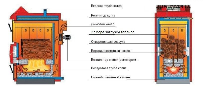
TTK can be divided into classical (grate) and pyrolysis (gas generator) . The classic version involves ordinary combustion of fuel with heat. Solid pyrolysis boilers are distinguished by the fact that the fuel and combustible gas emitted during its combustion are burned separately. This provides higher efficiency, a wide range of power, simplicity of the requirements for the chimney.
By "ordinary combustion of fuel" is meant that the fuel in such boilers burns in the loading chamber, where all the same processes take place at the same time as during the pyrolysis of wood . For this reason, in classic (grate) boilers it is not possible to obtain high-quality (complete) fuel combustion. As a result of incomplete combustion of fuel, tar, tar, (pyrolysis products), soot, ash are deposited on the heat exchanger of the boiler and a heat-insulating layer is formed, which in turn forces the boiler to generously share the heat generated with the environment.
As an advantage of classical boilers, it is sometimes indicated that it is possible to burn firewood with high humidity in them, but as for me, to sink with raw wood - do not respect yourself.
It does not matter in which boiler, pyrolysis or traditional, firewood, before starting to give heat, must pass the initial stages of pyrolysis , namely the heating and evaporation of moisture. So, if we use wood for heating with a humidity of 20% (this is 10 kg of dry firewood, pour 2 liters of water on top), that is, one-fifth of the weight of ballast in them, for heating and evaporating which will also have to spend some of the fuel will be used for home heating.

If we are to be absolutely accurate, the fuel does not burn "directly", the gaseous pyrolysis products burn. This means that before firewood starts to burn , that is, is oxidized by atmospheric oxygen with heat, they must be heated to the temperature of evaporation of moisture in them, then the process of evaporation of this moisture must pass, and then pyrolysis and combustion will begin . Moreover, the processes of the first and second stages proceed with the absorption of heat, which is so necessary for the pyrolysis of the wood itself, without which there will be no burning process itself.
 If, after reading, you no longer plan to drown with raw wood, then based on your life experience, I would recommend the pyrolysis boiler.
Before that, I already had two years of experience in operating the KALVIS – 2-70 shaft grate boiler. From the identified shortcomings, I note that it was impossible to clean its heat exchanger from the resins deposited on it without first heating to a temperature above 60 ° C. In the end, realizing all the technological flaws of this design, I decided to turn to specialists for its radical alteration. As a result of this deep modernization, I became the owner of the pyrolysis boiler.
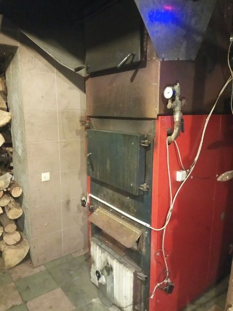
It is better to place the boiler in a room specially designated for it, since I have not yet seen boilers that do not smoke indoors when reloading fuel (and mine, moreover, sometimes smokes also because of imperfect construction).
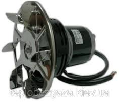
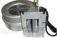
In addition, boilers are usually equipped with a smoke exhauster or a pressurization fan , which are usually quite decently noisy. The remaining control mechanisms for the CO units (circulation pumps, air damper drives, chimney dampers and electric ball valves) work almost silently.
Among other things, it is necessary to take into account, the boiler for its work will require a large flow of air into the room in which it is located, which will cause the occurrence of cold drafts. Of all the above, the boiler is better to have in a separate room in the body of the house.
My chimney is located vertically without bends and is part of the inner wall of the house, and during operation of the boiler radiates additional heat into the house.
Since the boiler is a unit in which the generated heat is transferred to the coolant water, there are no “hot” parts on its surface, since it does not heat up above the boiling point of water. In addition, the water jacket is outside, usually protected by a casing, the temperature of which rarely exceeds 30–35 degrees.
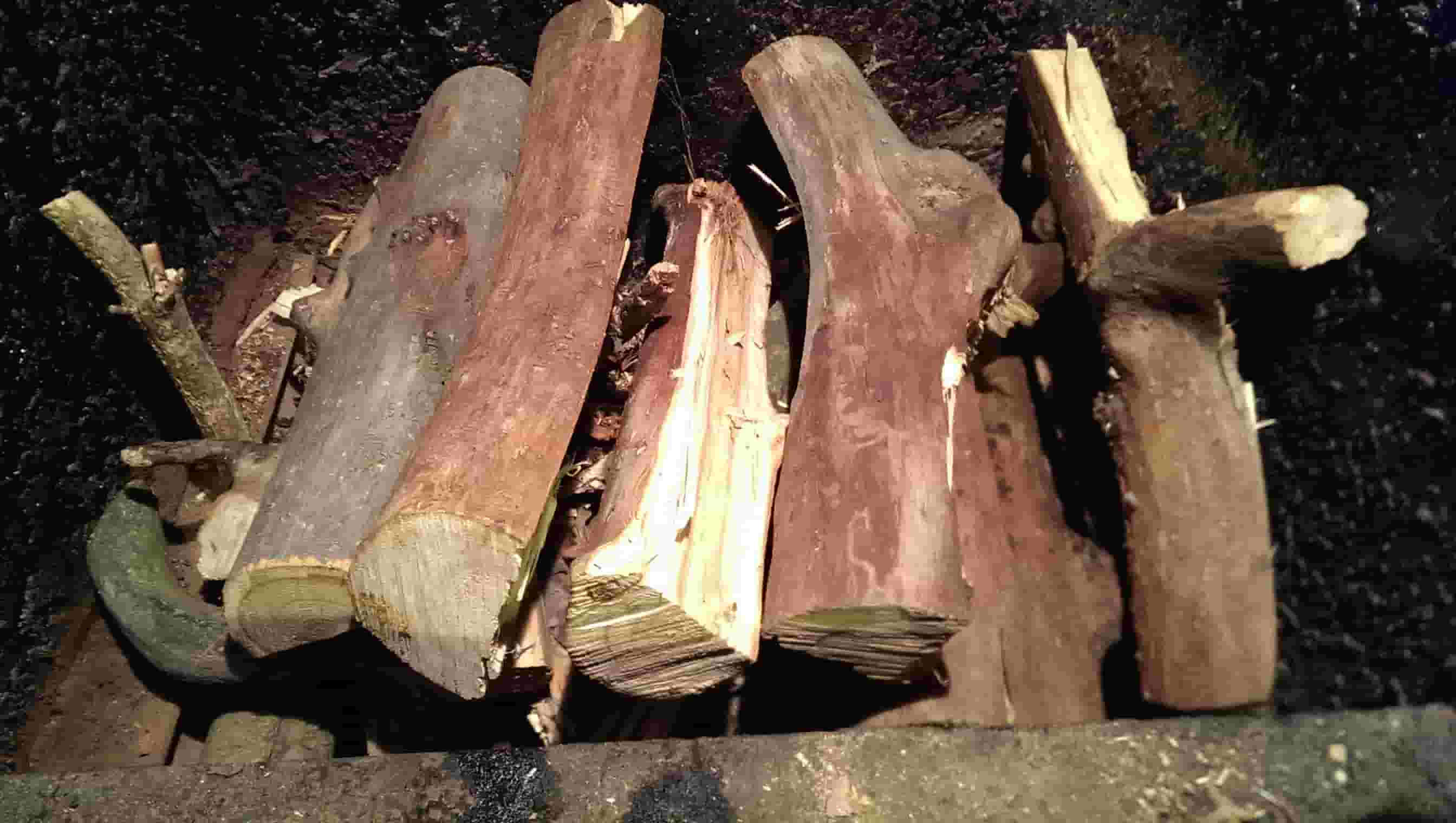
 The main fuel for the pyrolysis boiler is wood.
Any firewood is suitable: coniferous, deciduous, pine, oak, birch, etc. They all have about the same calorific value.. Solid breeds, such as oak, have a higher calorific value, but they are more expensive, so I don’t see much sense in chasing them. Any dead tree, fallen or deadwood, is excellent for harvesting. The main thing is that the wood is not raw and not expensive, it is better to personally harvested, and for the wallet and health is more useful (you can easily save on a subscription to a fitness club). Partly because when buying on the side it is difficult to meet all the above conditions, I do not like to buy firewood. Somehow, in the first heating season, I was brought a car of wood from the forestry enterprise, so their shoots were released in the spring in the yard and rooted in my yard. Since then, firewood is harvested only independently.
In addition to firewood, the pyrolysis boiler gladly consumes straw, pellets, shavings, peat briquettes and ordinary peat, sorted household waste (paper, plastic, packaging, everything except PVC) and all this seasoned with waste oil or any other waste of liquid hydrocarbons.
But the best fuel for the boiler can be a car tire. The calorific value of an automobile tire significantly exceeds the calorific value of the best wood species and is 32 GJ / t.. Compared with it can, perhaps, the calorific value of high-quality coal. To all this, the tire has zero humidity, which is also a positive thing. Well, if someone else has doubts that the tire can burn pretty well, you can look at the gases coming out of my pipe and at the fire in the pyrolysis chamber.
The fact that not only I regard the tire as an excellent fuel can be estimated by the number of
ads that offer steel cord remaining after its burning.
To ensure fire safety in the boiler room, I placed two Buran 2.5 automatic powder fire extinguishers and an independent smoke detector on its ceiling .
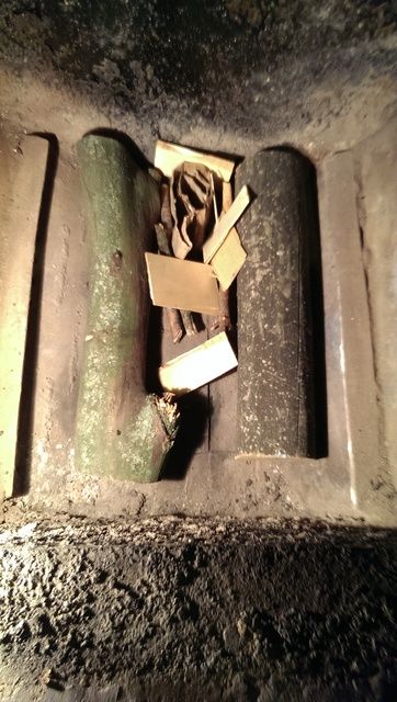
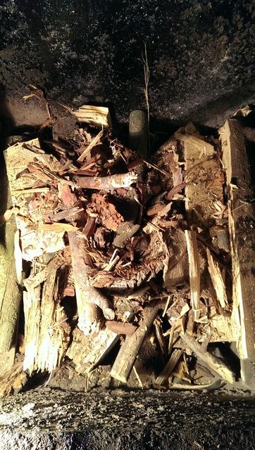
 It is easier to kindle the boiler with a small amount of firewood (this tab is carried out through the lower window to load firewood), but if you wish, you can start the boiler with a full load (for this load, the upper window for loading firewood is used).
When starting with a full load, I kindle the boiler through a pyrolysis burner using a wick from a corrugated cardboard pre-inserted into it (top view of the pyrolysis burner through the lower fuel loading window). It also makes it easier to ignite a small amount of used engine oil and small wood chips .
The pyrolysis chamber of the boiler (also known as the ashpit) must be cleaned every time after the heating cycle (approximately 10 to 12 hours of continuous operation), since its volume is limited and the pyrolysis gases still need to burn somewhere. I try to clean the heat exchangers of the boiler through the heating cycle, that is, about twice a month, because the degree of their purity depends on the efficiency of heat recovery generated in the pyrolysis chamber. Usually, after one cycle of heating, there remains a bucket of ash and almost pure steel cord from tires. Both ash and steel cord, as it turned out, are a valuable product for future use.
Products of complete combustion of TTC fuel are carbon dioxide, water and ash. That's it, water vapor and stains the smoke white on a cold chimney. Soot can become a product of incomplete combustion of TTK fuel. A significant amount of it can paint smoke black, and a small amount, mixed with water vapor, in various shades of gray.
On the front of my boiler are three doors:
Air to the fuel in my TTK is supplied through three air dampers to different zones of the boiler, which makes it possible to obtain the most efficient combustion of fuel.
The presence of 3 air dampers, a graph of the temperature in the chimney and a video camera in the pyrolysis chamber allows minimizing heat losses and obtaining the most efficient combustion of not only different types of wood, but also more caloric fuel, such as sorted household waste and worn car tires.
My boiler, like most pyrolysis boilers, was born with one valve (it is now average in height, it is also the main one). The damper is located on the front of the boiler, below the lower fuel loading door.
Air is fed through it to the fuel located above the burner and covers about 100 cm3 of wood. This is the amount of fuel that is involved in the main combustion process. The same amount of fuel forms a coal cushion, on which pyrolysis gases ignite .
The top flap is located under the skin, above the bottom fuel loading door. It appeared later, its task is to form an additional volume of pyrolysis gases, already after the fuel located in the coverage area of the middle flap passed from the first to the third pyrolysis stage, and no longer emits enough flammable gases in relation to the supplied (middle damper) air volume.
The bottom flap has already appeared last because of the need to supply additional air volume when burning more high-calorie fuel than wood, for example, a car tire. The lower flap is located above the door of the combustion chamber and supplies additional air to the combustion chamber.
As drives for these dampers, inexpensive, but quite suitable for this purpose, MG996R 15kg servos are used .
Usually, the happy owners of the TTC, go through the natural stages of evolution:
 I was more fortunate than the others, even in the process of designing a house, I planned for myself a place for TA, successfully passing this initial stage.
As a heat accumulator, you can use any capacity that will withstand the pressure in your CO (I do not exceed 1.5 kg / cm2), or make TA indirect heating (the water circuit of this TA exchanges heat with the boiler circuit through an additional heat exchanger), then it will be easier to fit into the space of the room. Here you can learn more about mine.
It is also necessary to take into account that the temperature of the water in the TA often reaches 94 ° C, therefore the material from which the TA is made and the pipe supplying the coolant to it must withstand these temperatures.
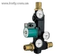
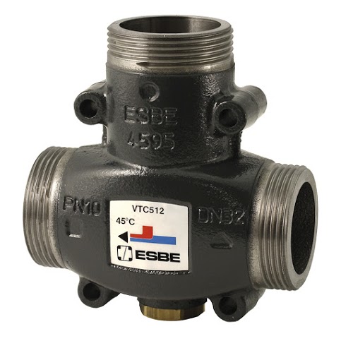
It is not necessary to put the heat accumulator in the boiler room next to the TTC (even better outside), you can mount it in any room that is convenient for you ( you can even do this ). Laddomat 21
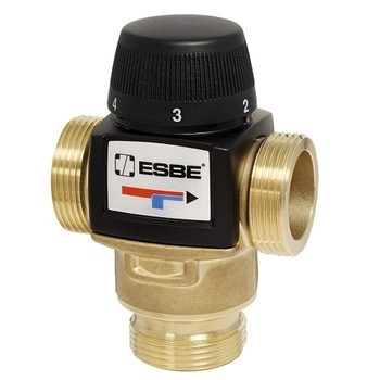
also had to be purchased , although it was quite possible to do with a three-way mixing valve and a circulation pump of the boiler circuit. It also took thermostatic mixing valves for the contour of the warm floor and the radiator circuit, although life later showed that radiators in CO with TTC and TA are meaningless. It turned out not superfluous in CO with TTK and a boiler of indirect heating
, well, already on the little things: the expansion tank, ball valve with electric TA circuit, the boiler circuit and the boiler circuit. Circulating pumps for boiler contours of indirect heating, underfloor heating and radiators.
As their JI exploited, it gradually became clear that the system, in the form in which it was born, had significant flaws.
It turned out that the heating systems based on TTC + TA, it makes sense to meet a number of conditions:
At first, it was necessary to manually connect the TTC to the CO during start-up and also manually disconnect it from it. Manually divide the heat fluxes both at the start of the start of the TTK and already in the process of the boiler operation, when excess heat is formed. In addition, the regular air damper regulator was too inertial and could not cope with the tasks assigned to it.
And then it was decided to transfer some of its simple functions of boiler control to the fragile shoulders of automation. Using an electronic control unit (CU), saved me from performing a variety of routine operations. Also, in passing, the control unit copes with such a trivial task as protecting the TTC from overheating, that is, it does what the overwhelming majority of factory-mounted control unit boilers do.
My first TTK control unit was far from perfect.

Every time when I needed to correct or change the logic of the work of CO, my head was puffy when I looked at this scheme and tried to understand how it works.
 In the end, with the participation of good people, the BU acquired the look that it has today, as well as the functionality that is so necessary for me.
The screen displays in graphical form the current state of the main CO nodes that need to be monitored. At the same time, the screen is not overloaded with information, and it is easy to read.
Additional information about what equipment is currently used by the control unit can be obtained from the LEDs of the relay unit.
The control unit of my boiler is assembled on the basis of the Arduino Mega 2560 module. The choice fell on Arduino, because it is widely distributed, easily accessible, well documented, there are many lessons on its programming in the network, a huge friendly online community that will help, tell, teach.
It Arduino allows you to implement the functionality of your device, limited only by your imagination. For example, your control unit in winter can control the TTC, but it is enough to change the firmware in it and connect the power device connector to another group, and it will control the irrigation system of your backyard or, for example, the greenhouse. With the factory BU TTK such tricks can not be done.

My boiler control unit is connected to the cloud service , this allows you to remotely monitor the system status, and, if necessary, also remotely, make adjustments to the operation of the boiler and the heating system as a whole. Why is asked the remote control of the heating system and in particular the remote control over the operation of the TTC? I believe that only a very brave person can afford to leave a working boiler only under the supervision of a control unit costing a little more than $ 100. I gained confidence in the need for remote control, as I acquired my personal eight-year operating experience with TTK.
This serviceIt provides an extremely useful opportunity to graphically present data from temperature sensors located at key points of the CO, which in turn not only gives an idea of the current static state of the CO, but also the dynamics of the development of the processes occurring there. So, in particular, the data obtained from the “Charts” tab gives an idea of the current state of the CO, the correctness of its individual components in accordance with a given control program, and, unlike the data received from the control monitor, gives an idea of the dynamics of this data, the rate of change and direction of movement (increase or decrease), which is especially important at the time of the threshold (critical) values of temperatures.
Whether the TTC was fed with cold water from TA or not, we can remotely, quickly track the “Boiler inlet” graph, and if this feed had the expected result for protecting the boiler from overheating, we can track it in the “Boiler outlet” chart. If the expected decrease in water temperature at the boiler inlet / outlet did not occur, it means that for some reason the tap of the TA circuit did not open and the owner of the boiler needs to take adequate measures to protect the TTC.
Also, the data obtained from these graphs allow you to quickly notice and eliminate the boiler maker's mistakes made while operating the boiler.
In particular, thanks to the “Chimney” schedule, I noticed in time that I forgot to return the distribution valve to the working position, which sends combustion products bypassing the boiler heat exchanger to the chimney (it is usually transferred to this position when reloading the fuel, to reduce smoke in the room) which in turn led to a cast of temperature in the chimney above 250 ° C.
Thus, the graphics in the “History” tab provide an opportunity to analyze the work of the entire system over the past periods and to predict the next launch of the TTC in accordance with the needs of the residents of the house. In addition, this view from the side gives understanding for further improvement of the heating system.
Sometimes people ask me why I chose wood heating? I answer, I was just lucky that I did not have a gas pipe nearby. Now I am a happy person, I don’t know how much “gas for the population” costs, I don’t take part in the discussion of tariffs for heating, it just does not bother me.
 Will a woman or a teenager cope with a solid fuel boiler? I think so, especially if there is no other alternative. After all, they coped with it somehow earlier, until the general “gas dependence” developed.
Cope and now in far from poor countries, for example, Germany or Spain.
By the way, I somehow, just in case (well, there the disease will prevail, or frankly laziness will be) installed, in addition to the TTK, also an electric boiler for 45 kW, but for 6 years I turned it on only once, when I checked it after installation.
My good friends, worrying about me, sometimes ask: “Isn't it a fuss for you? Did you want to drop everything and move to where there is central heating? ” So, not in the burden, on the contrary, for me it is a very exciting activity to realize my creative needs. You see, I sing terribly, I dance badly, I don’t write pictures at all, what else can I ask to brighten up long winter evenings?
Let's figure it out together.
A bit of theory
Heating systems (CO) with a solid fuel boiler (TTR) are batch systems in which the boiler generates heat only when there is fuel in it. In this regard, the TTC owners, sooner or later, acquire heat accumulators that accumulate the excess heat generated during the operation of the TTC and give it to the house after the fuel in the boiler has run out.
TTK can be divided into classical (grate) and pyrolysis (gas generator) . The classic version involves ordinary combustion of fuel with heat. Solid pyrolysis boilers are distinguished by the fact that the fuel and combustible gas emitted during its combustion are burned separately. This provides higher efficiency, a wide range of power, simplicity of the requirements for the chimney.
By "ordinary combustion of fuel" is meant that the fuel in such boilers burns in the loading chamber, where all the same processes take place at the same time as during the pyrolysis of wood . For this reason, in classic (grate) boilers it is not possible to obtain high-quality (complete) fuel combustion. As a result of incomplete combustion of fuel, tar, tar, (pyrolysis products), soot, ash are deposited on the heat exchanger of the boiler and a heat-insulating layer is formed, which in turn forces the boiler to generously share the heat generated with the environment.
As an advantage of classical boilers, it is sometimes indicated that it is possible to burn firewood with high humidity in them, but as for me, to sink with raw wood - do not respect yourself.
It does not matter in which boiler, pyrolysis or traditional, firewood, before starting to give heat, must pass the initial stages of pyrolysis , namely the heating and evaporation of moisture. So, if we use wood for heating with a humidity of 20% (this is 10 kg of dry firewood, pour 2 liters of water on top), that is, one-fifth of the weight of ballast in them, for heating and evaporating which will also have to spend some of the fuel will be used for home heating.
If we are to be absolutely accurate, the fuel does not burn "directly", the gaseous pyrolysis products burn. This means that before firewood starts to burn , that is, is oxidized by atmospheric oxygen with heat, they must be heated to the temperature of evaporation of moisture in them, then the process of evaporation of this moisture must pass, and then pyrolysis and combustion will begin . Moreover, the processes of the first and second stages proceed with the absorption of heat, which is so necessary for the pyrolysis of the wood itself, without which there will be no burning process itself.
My choice
If, after reading, you no longer plan to drown with raw wood, then based on your life experience, I would recommend the pyrolysis boiler. Before that, I already had two years of experience in operating the KALVIS – 2-70 shaft grate boiler. From the identified shortcomings, I note that it was impossible to clean its heat exchanger from the resins deposited on it without first heating to a temperature above 60 ° C. In the end, realizing all the technological flaws of this design, I decided to turn to specialists for its radical alteration. As a result of this deep modernization, I became the owner of the pyrolysis boiler.
Installation
It is better to place the boiler in a room specially designated for it, since I have not yet seen boilers that do not smoke indoors when reloading fuel (and mine, moreover, sometimes smokes also because of imperfect construction).
In addition, boilers are usually equipped with a smoke exhauster or a pressurization fan , which are usually quite decently noisy. The remaining control mechanisms for the CO units (circulation pumps, air damper drives, chimney dampers and electric ball valves) work almost silently.
Among other things, it is necessary to take into account, the boiler for its work will require a large flow of air into the room in which it is located, which will cause the occurrence of cold drafts. Of all the above, the boiler is better to have in a separate room in the body of the house.
My chimney is located vertically without bends and is part of the inner wall of the house, and during operation of the boiler radiates additional heat into the house.
Since the boiler is a unit in which the generated heat is transferred to the coolant water, there are no “hot” parts on its surface, since it does not heat up above the boiling point of water. In addition, the water jacket is outside, usually protected by a casing, the temperature of which rarely exceeds 30–35 degrees.
Logging and not only.
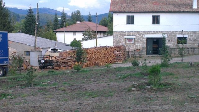
The main fuel for the pyrolysis boiler is wood. Any firewood is suitable: coniferous, deciduous, pine, oak, birch, etc. They all have about the same calorific value.. Solid breeds, such as oak, have a higher calorific value, but they are more expensive, so I don’t see much sense in chasing them. Any dead tree, fallen or deadwood, is excellent for harvesting. The main thing is that the wood is not raw and not expensive, it is better to personally harvested, and for the wallet and health is more useful (you can easily save on a subscription to a fitness club). Partly because when buying on the side it is difficult to meet all the above conditions, I do not like to buy firewood. Somehow, in the first heating season, I was brought a car of wood from the forestry enterprise, so their shoots were released in the spring in the yard and rooted in my yard. Since then, firewood is harvested only independently.
In addition to firewood, the pyrolysis boiler gladly consumes straw, pellets, shavings, peat briquettes and ordinary peat, sorted household waste (paper, plastic, packaging, everything except PVC) and all this seasoned with waste oil or any other waste of liquid hydrocarbons.
But the best fuel for the boiler can be a car tire. The calorific value of an automobile tire significantly exceeds the calorific value of the best wood species and is 32 GJ / t.. Compared with it can, perhaps, the calorific value of high-quality coal. To all this, the tire has zero humidity, which is also a positive thing. Well, if someone else has doubts that the tire can burn pretty well, you can look at the gases coming out of my pipe and at the fire in the pyrolysis chamber.
Gases from burning tires
Fire burning tires
So look, prepared for loading into the boiler, car tires
The fact that not only I regard the tire as an excellent fuel can be estimated by the number of
ads that offer steel cord remaining after its burning.
Ecological norms and their violation
Также должен акцентировать внимание на том, что ни в ком случае не призываю к повсеместному сжиганию автомобильных шин в домашних отопительных агрегатах. Живя в обществе среди людей, обустраивая свой быт, мы не должны причинять неудобства своим соседям, в том числе наши действия не должны нарушать законодательства государств, гражданами которых мы являемся.
Шина как топливо упоминается мною в этой статье только как частный удачный опыт, который стал возможен после основательной модернизации серийного бытового котла, при условии постоянного пристального контроля за процессом горения через видеокамеру и оперативного управления.
Шина как топливо упоминается мною в этой статье только как частный удачный опыт, который стал возможен после основательной модернизации серийного бытового котла, при условии постоянного пристального контроля за процессом горения через видеокамеру и оперативного управления.
To ensure fire safety in the boiler room, I placed two Buran 2.5 automatic powder fire extinguishers and an independent smoke detector on its ceiling .
Ignition
It is easier to kindle the boiler with a small amount of firewood (this tab is carried out through the lower window to load firewood), but if you wish, you can start the boiler with a full load (for this load, the upper window for loading firewood is used). When starting with a full load, I kindle the boiler through a pyrolysis burner using a wick from a corrugated cardboard pre-inserted into it (top view of the pyrolysis burner through the lower fuel loading window). It also makes it easier to ignite a small amount of used engine oil and small wood chips .
Combustion products
The pyrolysis chamber of the boiler (also known as the ashpit) must be cleaned every time after the heating cycle (approximately 10 to 12 hours of continuous operation), since its volume is limited and the pyrolysis gases still need to burn somewhere.
I try to clean the heat exchangers of the boiler through the heating cycle, that is, about twice a month, because the degree of their purity depends on the efficiency of heat recovery generated in the pyrolysis chamber. Usually, after one cycle of heating, there remains a bucket of ash and almost pure steel cord from tires. Both ash and steel cord, as it turned out, are a valuable product for future use.Products of complete combustion of TTC fuel are carbon dioxide, water and ash. That's it, water vapor and stains the smoke white on a cold chimney. Soot can become a product of incomplete combustion of TTK fuel. A significant amount of it can paint smoke black, and a small amount, mixed with water vapor, in various shades of gray.
Boiler design
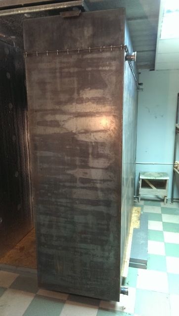
On the front of my boiler are three doors:
- The upper door is needed in order to increase the volume of a single load. The more you manage to load firewood at a time, the less often you have to do it.
- The middle door is needed to service the boiler (cleaning from the ashes, preparing for the new kindling), through the uppermost door it is simply impossible to do this. Behind it is the boot camera.Appearance boot camera
 Эта камера ещё называется газогенераторной, так как именно в ней и происходит процесс пиролиза дров.
 - Behind the lower door is the pyrolysis gas combustion chamber.Some details about the location of the combustion chamber
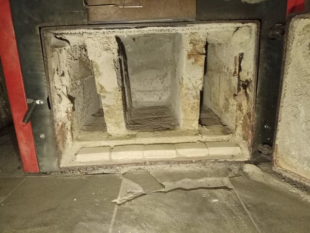 Камера сгорания (камера дожига) расположена под камерой загрузки топлива для того, чтобы локализовать определенный объем топлива участвующего в процессе горения. То есть, в пиролизном котле горят только те дрова, которые находятся в зоне охвата воздушных заслонок (это ниже средней дверцы и немного на высоте самой средней дверцы), остальное топливо — просто запас, который по мере выгорания опускается в зону горения. Если же пиролизную камеру расположить сверху, а топливо поджигать снизу, то пламя подымаясь снизу вверх по дровам будет пиролизовать все топливо сразу и вместо горения мы получим много дыма и как следствие смолистые вещества на теплообменнике.
Air to the fuel in my TTK is supplied through three air dampers to different zones of the boiler, which makes it possible to obtain the most efficient combustion of fuel.
The presence of 3 air dampers, a graph of the temperature in the chimney and a video camera in the pyrolysis chamber allows minimizing heat losses and obtaining the most efficient combustion of not only different types of wood, but also more caloric fuel, such as sorted household waste and worn car tires.
A bit of theory
Обычно в ТТ пиролизные котлы воздух подается в строгом заранее спроектированном соотношении без учета особенности топлива, его фактической влажности и стадий, которые оно проходит по мере его выгорания в котле. Это приводит к тому, что иногда воздуха вполне достаточно для эффективного сгорания проектного топлива (к примеру сосновых дров), но чаще воздуха либо меньше чем нужно, (и тогда продукты неполного сгорания топлива конденсируются на теплообменнике ТТК в виде дегтя), либо больше чем нужно (и тогда лишний воздух не участвующий в процессе горения остужает теплообменник, и уносит в атмосферу драгоценное тепло которое сгенерировал ТТК).
My boiler, like most pyrolysis boilers, was born with one valve (it is now average in height, it is also the main one). The damper is located on the front of the boiler, below the lower fuel loading door.
Air is fed through it to the fuel located above the burner and covers about 100 cm3 of wood. This is the amount of fuel that is involved in the main combustion process. The same amount of fuel forms a coal cushion, on which pyrolysis gases ignite .
The top flap is located under the skin, above the bottom fuel loading door. It appeared later, its task is to form an additional volume of pyrolysis gases, already after the fuel located in the coverage area of the middle flap passed from the first to the third pyrolysis stage, and no longer emits enough flammable gases in relation to the supplied (middle damper) air volume.
Top flap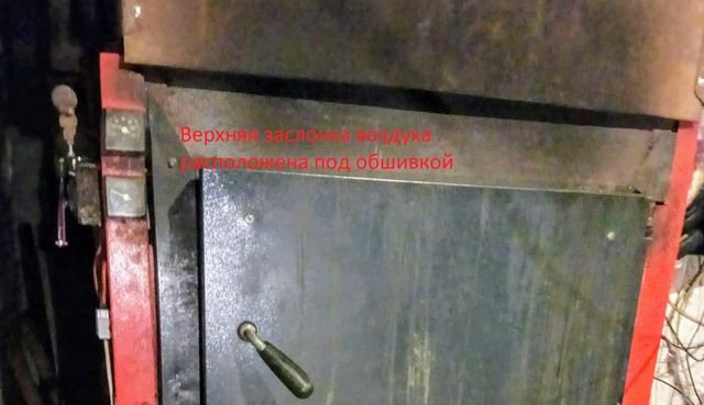
The bottom flap has already appeared last because of the need to supply additional air volume when burning more high-calorie fuel than wood, for example, a car tire. The lower flap is located above the door of the combustion chamber and supplies additional air to the combustion chamber.
Middle and lower flaps
As drives for these dampers, inexpensive, but quite suitable for this purpose, MG996R 15kg servos are used .
Heating system
Usually, the happy owners of the TTC, go through the natural stages of evolution:
- Acquisition of the boiler and the knowledge of the first joy of the heat brought to their home. They feed it with small portions of firewood, they feed often and with pleasure.
- Then try to stretch the time between feeding. Then they try to experiment with various types of food: they drown it exclusively with oak, acacia, and even rare coal in our area.
- In the end, comes the understanding that "the boiler exists for me," and not "I am for the boiler."
- After that, the owner of the boiler begins to look for a place in the house under the heat accumulator (TA).
I was more fortunate than the others, even in the process of designing a house, I planned for myself a place for TA, successfully passing this initial stage. As a heat accumulator, you can use any capacity that will withstand the pressure in your CO (I do not exceed 1.5 kg / cm2), or make TA indirect heating (the water circuit of this TA exchanges heat with the boiler circuit through an additional heat exchanger), then it will be easier to fit into the space of the room. Here you can learn more about mine.
It is also necessary to take into account that the temperature of the water in the TA often reaches 94 ° C, therefore the material from which the TA is made and the pipe supplying the coolant to it must withstand these temperatures.
It is not necessary to put the heat accumulator in the boiler room next to the TTC (even better outside), you can mount it in any room that is convenient for you ( you can even do this ). Laddomat 21
also had to be purchased , although it was quite possible to do with a three-way mixing valve and a circulation pump of the boiler circuit. It also took thermostatic mixing valves for the contour of the warm floor and the radiator circuit, although life later showed that radiators in CO with TTC and TA are meaningless. It turned out not superfluous in CO with TTK and a boiler of indirect heating
, well, already on the little things: the expansion tank, ball valve with electric TA circuit, the boiler circuit and the boiler circuit. Circulating pumps for boiler contours of indirect heating, underfloor heating and radiators.
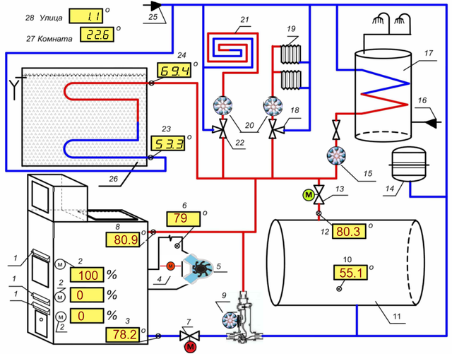
Legend
1. Заслонка подачи воздуха
2. Привод заслонки подачи воздуха TowerPro MG996R
3. Датчик температуры воды на входе в котел ( температура обратки) — ds18b20
4. Привод заслонки дымохода
5. Дымосос
6. Датчик температуры дыма — (ТХА)
7. Кран шаровый с электроприводом контура котла
8. Датчик температуры воды на выходе из котла ( температура подачи) — ds18b20
9. Насос циркуляционный контура котла, входящий в состав Ладдомат 21
10. Датчик температуры воды нижней части ТА №1 — ds18b20
11. Теплоаккумулятор №1 — 4м3
12. Датчик температуры воды в верхнем патрубке ТА №1 — ds18b20
13. Кран шаровый с электроприводом контура ТА
14. Расширительный бак
15. Насос циркуляционный бойлера косвенного нагрева
16. Вход системы водоснабжения
17. Бойлер косвенного нагрева
18. Термостатический смесительный клапан контура радиаторов
19. Радиаторы отопления
20. Насосы циркуляционные контура теплых полов и контура радиаторов
21. Теплый пол
22. Термостатический смесительный клапан контура теплого пола
23. Датчик температуры воды нижней части ТА №2- ds18b20
24. Датчик температуры воды в верхнем патрубке ТА №2 — ds18b20
25. Кран шаровый подпитки водой системы отопления
26. Теплоаккумулятор №2 (косвенного нагрева) — 4м3
27. Показания температуры с устройства «Комнатный термостат».
28. Показания температуры с устройства «Шлагбаум»
Automation
As their JI exploited, it gradually became clear that the system, in the form in which it was born, had significant flaws.
It turned out that the heating systems based on TTC + TA, it makes sense to meet a number of conditions:
- It seeks to send to TA only the excess heat from the TTC.
- Cut off TTC from the rest of the heating system (CO) after it stops generating heat, because after it burns out, TTC turns from the heat generator into its consumer and begins to drain the previously stored heat from the heat pump.
At first, it was necessary to manually connect the TTC to the CO during start-up and also manually disconnect it from it. Manually divide the heat fluxes both at the start of the start of the TTK and already in the process of the boiler operation, when excess heat is formed. In addition, the regular air damper regulator was too inertial and could not cope with the tasks assigned to it.
And then it was decided to transfer some of its simple functions of boiler control to the fragile shoulders of automation. Using an electronic control unit (CU), saved me from performing a variety of routine operations. Also, in passing, the control unit copes with such a trivial task as protecting the TTC from overheating, that is, it does what the overwhelming majority of factory-mounted control unit boilers do.
My first TTK control unit was far from perfect.
Schematic diagram
Every time when I needed to correct or change the logic of the work of CO, my head was puffy when I looked at this scheme and tried to understand how it works.
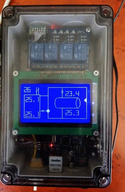
In the end, with the participation of good people, the BU acquired the look that it has today, as well as the functionality that is so necessary for me. The screen displays in graphical form the current state of the main CO nodes that need to be monitored. At the same time, the screen is not overloaded with information, and it is easy to read.
Additional information about what equipment is currently used by the control unit can be obtained from the LEDs of the relay unit.
Circuitry
The control unit of my boiler is assembled on the basis of the Arduino Mega 2560 module. The choice fell on Arduino, because it is widely distributed, easily accessible, well documented, there are many lessons on its programming in the network, a huge friendly online community that will help, tell, teach.
It Arduino allows you to implement the functionality of your device, limited only by your imagination. For example, your control unit in winter can control the TTC, but it is enough to change the firmware in it and connect the power device connector to another group, and it will control the irrigation system of your backyard or, for example, the greenhouse. With the factory BU TTK such tricks can not be done.
List of control unit elements
1. Arduino Mega 2560
2. Arduino Ethernet Shield W5100
3. Графический дисплей QC12864B
4. 4-канальный реле модуль – 2 шт.
5. DC-DC конвертер понижающий 4...38В в 1.25...32В для питания блока реле и дисплея.
6. DC-DC конвертер понижающий 4.5...28 В в 0.8...20 В 3А на MP1584 для отдельного питания «бутерброда» Arduino Mega 2560 + Arduino Ethernet Shield W5100
7. Цифровой усилитель термопары MAX31855
8. Термопара ТХА
9. Датчик температуры Dallas DS18B20 – 4 шт.
10. Привод заслонки подачи воздуха TowerPro MG996R
11. Резистор металлопленочный 4.7 кОм
Для питания БУ используется 12 вольтовый аккумулятор, который в свою очередь подключён к инвертору (600Вт). Он же обеспечивает работоспособность циркуляционных насосов СО.
Software
My boiler control unit is connected to the cloud service , this allows you to remotely monitor the system status, and, if necessary, also remotely, make adjustments to the operation of the boiler and the heating system as a whole. Why is asked the remote control of the heating system and in particular the remote control over the operation of the TTC? I believe that only a very brave person can afford to leave a working boiler only under the supervision of a control unit costing a little more than $ 100. I gained confidence in the need for remote control, as I acquired my personal eight-year operating experience with TTK.
This serviceIt provides an extremely useful opportunity to graphically present data from temperature sensors located at key points of the CO, which in turn not only gives an idea of the current static state of the CO, but also the dynamics of the development of the processes occurring there. So, in particular, the data obtained from the “Charts” tab gives an idea of the current state of the CO, the correctness of its individual components in accordance with a given control program, and, unlike the data received from the control monitor, gives an idea of the dynamics of this data, the rate of change and direction of movement (increase or decrease), which is especially important at the time of the threshold (critical) values of temperatures.
Whether the TTC was fed with cold water from TA or not, we can remotely, quickly track the “Boiler inlet” graph, and if this feed had the expected result for protecting the boiler from overheating, we can track it in the “Boiler outlet” chart. If the expected decrease in water temperature at the boiler inlet / outlet did not occur, it means that for some reason the tap of the TA circuit did not open and the owner of the boiler needs to take adequate measures to protect the TTC.
Also, the data obtained from these graphs allow you to quickly notice and eliminate the boiler maker's mistakes made while operating the boiler.
In particular, thanks to the “Chimney” schedule, I noticed in time that I forgot to return the distribution valve to the working position, which sends combustion products bypassing the boiler heat exchanger to the chimney (it is usually transferred to this position when reloading the fuel, to reduce smoke in the room) which in turn led to a cast of temperature in the chimney above 250 ° C.
Laddommat's work schedules
Противофазное поведение температур на графиках «Котел выход» и «Котел вход» обусловлено особенностями работы такого узла СО как Ладдомат 21 (на схеме обозначен № 9). Дело в том, что в его обязанность входить обеспечение поддержания температуры теплоносителя (в нашем случае вода) на входе в котел выше 55°С. Эта функция обеспечивается термостатическим клапаном, который входит в состав Ладдомат 21.
Так как система ТТК + Ладдомат 21 достаточна инерционна, то мы и наблюдаем на графике противофазное колебание температур. Такое колебание температур, на графиках «Котел выход» и «Котел вход» свидетельствует о нормальной работе СО в целом.
Schedule heat exchanger
По достижении пороговой температуры на выходе из котла выше 85°С. БУ ТТК дает команду на открытие шарового крана (№13), при этом горячая вода поступает уже не только в отопительные приборы дома (теплый пол и радиаторы), но и в ТА (№12), при этом холодная вода выходящая из ТА поступает на вход в ТТК, что в свою очередь приводит к снижению температуры на выходе из котла. Другими словами, всё избыточное тепло направляется в теплоаккумулятор.
По достижении пороговой температуры на выходе из котла выше 85°С. БУ ТТК дает команду на открытие шарового крана (№13), при этом горячая вода поступает уже не только в отопительные приборы дома (теплый пол и радиаторы), но и в ТА (№12), при этом холодная вода выходящая из ТА поступает на вход в ТТК, что в свою очередь приводит к снижению температуры на выходе из котла. Другими словами, всё избыточное тепло направляется в теплоаккумулятор.
Overheating protection graphics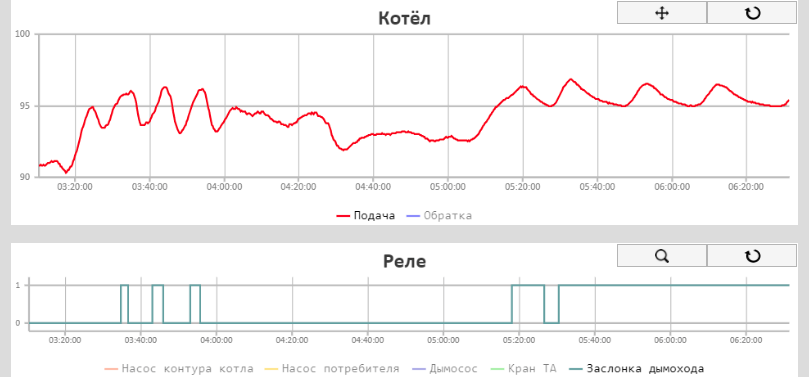
Если обычной меры (подпитки котла водой из ТА) оказалось не достаточной и температура на выходе из котла продолжает расти, то БУ ТТК даёт команду на закрытие воздушных заслонок и заслонки дымохода. Это позволяет снизить мощность котла и нормализовать температуру воды на его выходе. Таким образом происходит защита котла от перегрева.
Если обычной меры (подпитки котла водой из ТА) оказалось не достаточной и температура на выходе из котла продолжает расти, то БУ ТТК даёт команду на закрытие воздушных заслонок и заслонки дымохода. Это позволяет снизить мощность котла и нормализовать температуру воды на его выходе. Таким образом происходит защита котла от перегрева.
Manual adjustment of air dampers
График температуры в дымовой трубе, дает представление о стадии в которой находится ТТК (розжиг, активный пиролиз или выгорание остатка топлива) и в совокупности с видео, получаемым из пиролизной камеры, позволяет сделать вывод о состоянии пиролизной камеры и при необходимости удаленно (через сайт) откорректировать положение воздушных заслонок управляющих качеством сгорания топлива.
Так к примеру через 85 минут после запуска котла, уменьшилось выделение пиролизных газов в зоне охвата средней воздушной заслонкой, что привело к снижению температуры дыма. После смены положение заслонок, верхней — с 0% на 48% и средней — с 100% на 50% (где 0 – полностью закрыта, 100% — полностью открыта) температура дымовых газов снова выросла.
Charts the beginning of the active stage of pyrolysis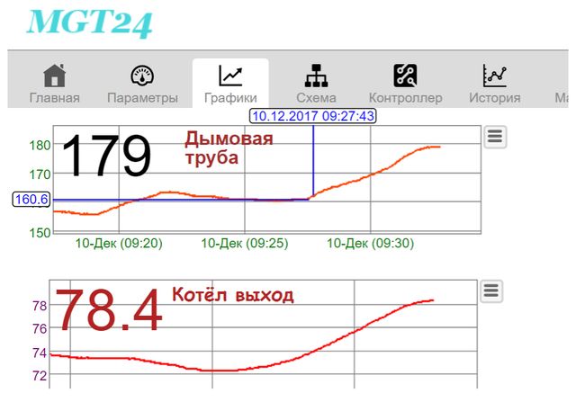
На этой части графика отображено начало активной стадии пиролиза шины, это видно по стремительному росту температуры дыма и температуры теплоносителя на выходе из котла, и как следствие увеличичение мощности котла. В этот момент нужно откорректировать положение воздушный заслонок на период активной стадии пиролиза шины.
На этой части графика отображено начало активной стадии пиролиза шины, это видно по стремительному росту температуры дыма и температуры теплоносителя на выходе из котла, и как следствие увеличичение мощности котла. В этот момент нужно откорректировать положение воздушный заслонок на период активной стадии пиролиза шины.
Chimney chart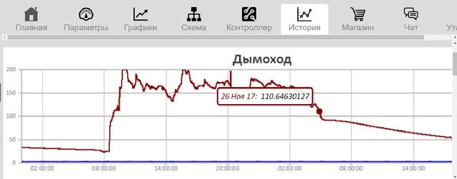
Глядя на этот график можно сделать вывод, что продолжительность работы котла составила примерно 20 часов 30 минут. После розжига котел перешел в активный режим (температура дыма более 110°С) примерно через 30 минут поджога дров. Еще через 30 минут температура дыма перешла границу 135°С и котел перешел в режим свободной тяги (БУ отключил дымосос и открыл заслонку дымохода). Далее котел работал на максимальной своей мощности, примерно, до 14 часов 30 минут (в это время, скорее всего, была произведена догрузка котла топливом).
В таком режиме котел доработал до 5 часов утра следующего дня и при понижении температуры в дымоходе ниже 110 град. БУ ТТК перевел котел в спящий режим (отключил циркуляционный насос («Ладдомат 21»), №9, закрыл шаровый кран контура котла №7, выключил дымосос №5, закрыл заслонку дымососа №4, открыл кран шаровый контура ТА №13).
Далее БУ снабжал дом теплом из ТА. У меня всего два ТА, каждый объемом, примерно по 4 м3. Разряжал я их поочередно, тепла накопленного в них мне хватило примерно на пять дней.
Thus, the graphics in the “History” tab provide an opportunity to analyze the work of the entire system over the past periods and to predict the next launch of the TTC in accordance with the needs of the residents of the house. In addition, this view from the side gives understanding for further improvement of the heating system.
Conclusion
Sometimes people ask me why I chose wood heating? I answer, I was just lucky that I did not have a gas pipe nearby. Now I am a happy person, I don’t know how much “gas for the population” costs, I don’t take part in the discussion of tariffs for heating, it just does not bother me.
Will a woman or a teenager cope with a solid fuel boiler? I think so, especially if there is no other alternative. After all, they coped with it somehow earlier, until the general “gas dependence” developed. Cope and now in far from poor countries, for example, Germany or Spain.
By the way, I somehow, just in case (well, there the disease will prevail, or frankly laziness will be) installed, in addition to the TTK, also an electric boiler for 45 kW, but for 6 years I turned it on only once, when I checked it after installation.
My good friends, worrying about me, sometimes ask: “Isn't it a fuss for you? Did you want to drop everything and move to where there is central heating? ” So, not in the burden, on the contrary, for me it is a very exciting activity to realize my creative needs. You see, I sing terribly, I dance badly, I don’t write pictures at all, what else can I ask to brighten up long winter evenings?