Principles of emulation based on CHIP-8
It is believed that before you start emulating complex systems, you need to start with something simple, for example with Chip-8. In this article I will try to consider all aspects of how you can write your implementation of this language in a virtual machine. Any programming language will do, but due to its simplicity I will choose Delphi.
Wait, do not immediately rush into the editor, first you need a pen and notebook, where we will write down all the important information for ourselves. It all starts with her search. First of all, this is of course Google. After half an hour of following the links, we can see how many implementations have already been written for any system, I don’t want to choose, but we won’t look at the source code of others, but write our own.
CHIP-8 is a language interpreter that was used in the late 70s and early 80s on some small commercial computers, such as RCA's TELMAC 1800 and COSMAC VIP, and cheap “create-it-yourself” computers of the time like ETI 660 and DREAM 6800 ...
CHIP-8 made it easy to program games. TELMAC 1800 and COSMAC VIP were based on RCA CDP-1802 processors. Both came with an audio cassette containing more than 12 games dated 1977. The interpreter had less than 40 commands, including mathematical, control of data flow, graphics and sound.
The interpreter had to be very small, due to memory limits in these computers: COSMAC VIP had 2Kb (but could be expanded to 32Kb), and TELMAC had 4Kb. CHIP-8 was only 512 bytes long.
The simplicity of the language made it possible to create the Pong, Brix, Invaders and Tank that we played at the very beginning of video games. A good programmer could put these games in less than 256 bytes.
Here is a short story about the CHIP-8 of one of the DREAM-6800 users:
" ... the DREAM and ETI 660 appeared in the Australian Electronic Magazines as assembly projects. These computers were combined and their incredibly low price (about $ 100), using a hexadecimal keyboard, the ability to reproduce very limited graphics of 64 x 32 pixels (the ETI 660 could get 64 x 48 or 64 x 64 when modified) transmitted to the TV, about one kilobyte of RAM, and the ability to run a high-level pseudo language called CHIP-8 (developed by RCA for demonstration tion of COSMAC graphics, it seems to me).
...
One day my older brother assembled a DREAM 6800. What a computer it was! Together with the DREAM & ETI 660 build articles, there were mountains of game listings for CHIP-8. Some games were less than 200 bytes or so, so entering them would not take forever. And these were great games. They were not slow. So CHIP-8 was very well designed for classic TV games. "
Paul Hyter (Author of the CHIP-8 interpreter for Amiga)
Later, CHIP-8 was used in the early 90s on HP48 calculators, because there was no way to write games on it faster. Almost all the original games from CHIP-8 worked with the CHIP48 interpreter , but many new ones were written, and
then a new version of the language, SUPER-CHIP, was released. It had all the features of the standard, but could already operate with 128x64 resolution.
All programs in CHIP-8 start at 200h, except for the ETI-660, which starts at 600h. This is done because the language interpreter itself is located at 000h-1FFh.
All memory is fully addressable and accessible. Since instructions occupy 16-bits, they usually have even addresses, and if some 8 bits are inserted inside the code, their addresses become odd.
Based on the 12 bits used for the memory address, we can calculate that the maximum amount of memory without tricks could be 4096 bytes (000h-FFFh). However, the addresses F00h-FFFh are occupied by video memory, and EA0h-EFFh is used to store the stack and internal variables of CHIP-8.
The interpreter uses 16 general-purpose registers with a volume of 8 bits. They are available as V0..VF. Moreover, VF is used as a flag for arithmetic operations, in the case of transfer, and a collision detector when drawing sprites.
There is also 1 address register (I) of 16 bits in size. Since the memory is only 4 kilobytes, the interpreter used only its lower 12 bits. However, the high 4 bits could be used for the font download function, since the font was located at 8110.
In addition to the registers, there were 2 timers. One is a delay timer, and one is an audio timer. Both had a length of 8 bits and reduced their contents 60 times per second, if they were not zero at that time. That is, they had a frequency of 60 hertz. If the sound timer had a value other than zero, it reproduced sound.
The dimension of the stack remained unknown, but it is customary to do it in 16 levels (2x16 bytes).
Graphics are rendered with 8 sprites at 1..15 pixels, which are encoded in bytes. The origin is in the upper left corner and starts at point 0. All coordinates are positive and are considered as the remainder of the division by 64 or 32, respectively. The output to the screen is in XOR mode. If one or more pixels are cleared (change their color from 1 to 0), the VF register is set to 01h and 00h otherwise. Chip-8 has a 4x5 pixel font containing the characters 0-9 and AF.
For clarity, consider an example of a sprite and its coding. Take an 8x5 sprite.
We
get the following set of bytes: To make it completely clear, take another 1 sprite 8x8.

The sprite will occupy 8 bytes and will have the following structure: The
keyboard for CHIP-8 is 16th and has the following appearance: You
can only argue and reason about the convenience and appropriateness of such a keyboard. But we will not depart from the original, because everything was developed specifically for such a keyboard.
It should be said right away that we will designate the address as NNN, KK - 8 bit constant, X and Y - 4 bit constants.
Now consider the list of commands.
0NNN Syscall nnn Call machine instruction instruction for processor 1802 with code NNN.
00CN * scdown n Scroll the screen down N lines.
00FB * Scright Scrolling the screen 4 pixels to the right
00FC * Scleft Scrolling the screen 4 pixels to the left
00FD * Exit the emulator
00FE * Low Set the graphic mode CHIP-8 (64x32)
00FF * High Set the graphic mode SUPER CHIP (128x64)
00E0 Cls Clear the screen
00EE Rts Return from routine
1NNN jmp nnn Transfer program execution to address NNN
2NNN jsr nnn Call a function at NNN. The previous address is pushed onto the stack.
3XKK skeq vx, kk Skip the next instruction (2 bytes) if VX = KK
4XKK skne vx, kk Skip the next instruction (2 bytes) if VX <> KK
5XY0 skeq vx, vy Skip the next instruction if VX = VY
6XKK mov vx, kk Write KK to the VX register
7XKK add vx, kk Write VX + KK to the VX register (According to information from Wikipedia and other sources it does not affect the flag)
8XY0 mov vx, vy Write the value of the register VY to
VX 8XY1 or vx, vy VX = VX OR VY.
8XY2 and vx, vy VX = VX AND VY
8XY3 xor vx, vy VX = VX XOR VY (undocumented in the original documents)
8XY4 add vx, vy VX = VX + VY. In VF = carry.
8XY5 sub vx, vy VX = VX - VY. (*) VF = NOT borrow.
8X06 shr vx VX = VX SHR 1 (VX = VX / 2), VF = carry
8XY7 sub vy, vx VX = VY - VX, VF = not borrow (*) (not documented in the original documents)
8XYE shl vx VX = VX SHL 1 (VX = VX * 2), VF = carry
9XY0 skne vx, vy Skip the following instruction if VX <> VY
ANNN mov I, nnn I = NNN
BNNN Jmi NNN Transfer program execution to NNN + V0
CXKK Rand vx, kk VX = (random number 0..255) AND KK
DXYN Draw vx, vy, n Draw a sprite of height N (for N = 0, consider N = 16) and a width of 8 at coordinates (VX, VY) starting in memory at the address contained in register I .VF = collision.
EX9E Skpr vx Skip the following instructions if the VX key is pressed.
EXA1 Skup vx Skip the following instructions if the number key in the VX is not pressed.
FX07 Gdelay vx VX = Delay timer
FX0A Key vx We wait for the button to be pressed and add it to VX.
FX15 Sdelay vx Delay timer = VX
FX18 Ssound vx Sound timer = VX
FX1E Add I, vx I = I + VX
FX29 Font vx Put in the I address of the font sprite 4 x 5 hexadecimal characters contained in VX
FX33 Bcd vx Place BCD representation of VX in memory to the addresses I..I + 2. For example, if VX contains 4Fh, then 00h 07h 09h will be written in memory, i.e. decimal representation 4Fh
FX55 Save vx Saves registers V0 ... VX in memory starting at address I
FX65 Load vx Loads registers V0 ... VX from memory starting at I
FX75 * Ssave vx Saves V0 ... VX (X <8) to HP48 flags
FX85 * Sload vx Loads V0 ... VX (X <8) from HP48 flags
* - this means the command is relevant only for the SUPER CHIP interpreter.
(*): When VX - VY occurs, VF is set to the denial of the loan. This means that if VX is greater than or equal to VY, VF will be set to 01, because the loan = 0. If VX is less than VY, VF is set to 00, because the loan = 1.
Using a piece of paper and a pen, we outline the font sprites. You will get something like this set:

Using it, write down the bytes of the value of each sprite.
It is believed that all emulation should take place in a cycle of approximately this type.
Here quit_pr is considered a sign of stopping the emulation, and can change not only outside, but also from inside the emulation.
One of the most important points to observe is compliance with the frequencies of the equipment and optimization. If it is incorrect to describe the emulation of even such a simple language as CHIP-8, you can get very low performance and extremely high CPU time, but the correct emulation will provide sufficient performance at minimal cost.
Using Delphi, I decided to develop a system emulation as a class and gave it the name “TCpu1802”, based on the model of the processor used inside this system. Consider the main run procedure for it.
First, at startup, we activate two standard for CHIP-8 timers and one, entered independently, to redraw the screen. Cycle - a variable containing the current cycle of commands, the call of each command increases the cycle by one. Every second action we will try to pause the interpreter for cpumulty milliseconds. This is necessary so that speeding does not occur.
Soundtimer and Drawtimer timers have an interval of 17 milliseconds, that is, they operate at a frequency of 58.82 hertz, which is as close as possible to the original.
Drawtimer delay is set to 10 milliseconds. That is, on average, rendering will be performed every 3-4 commands of the interpreter. Allocation to the timer is done so as not to clog the process of executing the interpreter and allows using regular means to perform parallelization of processes.
Let's look at the list of variables that we need to complete the emulation itself:
According to the architecture, video memory is located in the same amount of RAM as everything else, however, constant reading and writing there, examining bytes and analyzing them, would take up a lot of processor resources and is impractical, however, assuming that some program can read something directly from there, if reading from that memory area occurs, we can simply call an additional procedure called mirrorvideomem, which allows us to write the current contents of the video memory there. Such a solution is effective, although it causes a slightly greater use of RAM. The mirrorstack procedure is similar.
Before writing a processor, you can notice that each command is conditionally divided into 4 sections of 4 bits. To work with them, the opcode data type was introduced (type opcode = array [0..3] of byte;).
I will not dwell on converting and reading the next data from memory, however, I will pay attention to the structure of the run procedure that performs emulation. For optimization purposes, it uses not “if then else”, but “case”, and moreover, a number of commands allow you to use them using assembler, which further speeds up the emulation. Here is an example of such a command:
Now, having considered all the moments of emulation, you can write your own CHIP-8 emulation. I hope you enjoyed my article and it was useful. Thank you for reading.
Used articles:
A CHIP-8 / SCHIP emulator
By David WINTER (HPMANIAC)
Wikipedia
Module
source : source
It was for her that I received an invitation from the user nsinreal , for which many thanks to him.
The request not to consider as “copy-paste” the article that appeared an hour before the publication of this one, because it could not be sent. Please consider that we did not see each other's articles, due to the different contents of the modules and different approaches to emulation, thanks in advance.
Wait, do not immediately rush into the editor, first you need a pen and notebook, where we will write down all the important information for ourselves. It all starts with her search. First of all, this is of course Google. After half an hour of following the links, we can see how many implementations have already been written for any system, I don’t want to choose, but we won’t look at the source code of others, but write our own.
Historical reference
CHIP-8 is a language interpreter that was used in the late 70s and early 80s on some small commercial computers, such as RCA's TELMAC 1800 and COSMAC VIP, and cheap “create-it-yourself” computers of the time like ETI 660 and DREAM 6800 ...
CHIP-8 made it easy to program games. TELMAC 1800 and COSMAC VIP were based on RCA CDP-1802 processors. Both came with an audio cassette containing more than 12 games dated 1977. The interpreter had less than 40 commands, including mathematical, control of data flow, graphics and sound.
The interpreter had to be very small, due to memory limits in these computers: COSMAC VIP had 2Kb (but could be expanded to 32Kb), and TELMAC had 4Kb. CHIP-8 was only 512 bytes long.
The simplicity of the language made it possible to create the Pong, Brix, Invaders and Tank that we played at the very beginning of video games. A good programmer could put these games in less than 256 bytes.
Here is a short story about the CHIP-8 of one of the DREAM-6800 users:
" ... the DREAM and ETI 660 appeared in the Australian Electronic Magazines as assembly projects. These computers were combined and their incredibly low price (about $ 100), using a hexadecimal keyboard, the ability to reproduce very limited graphics of 64 x 32 pixels (the ETI 660 could get 64 x 48 or 64 x 64 when modified) transmitted to the TV, about one kilobyte of RAM, and the ability to run a high-level pseudo language called CHIP-8 (developed by RCA for demonstration tion of COSMAC graphics, it seems to me).
...
One day my older brother assembled a DREAM 6800. What a computer it was! Together with the DREAM & ETI 660 build articles, there were mountains of game listings for CHIP-8. Some games were less than 200 bytes or so, so entering them would not take forever. And these were great games. They were not slow. So CHIP-8 was very well designed for classic TV games. "
Paul Hyter (Author of the CHIP-8 interpreter for Amiga)
Later, CHIP-8 was used in the early 90s on HP48 calculators, because there was no way to write games on it faster. Almost all the original games from CHIP-8 worked with the CHIP48 interpreter , but many new ones were written, and
then a new version of the language, SUPER-CHIP, was released. It had all the features of the standard, but could already operate with 128x64 resolution.
Architecture
All programs in CHIP-8 start at 200h, except for the ETI-660, which starts at 600h. This is done because the language interpreter itself is located at 000h-1FFh.
All memory is fully addressable and accessible. Since instructions occupy 16-bits, they usually have even addresses, and if some 8 bits are inserted inside the code, their addresses become odd.
Based on the 12 bits used for the memory address, we can calculate that the maximum amount of memory without tricks could be 4096 bytes (000h-FFFh). However, the addresses F00h-FFFh are occupied by video memory, and EA0h-EFFh is used to store the stack and internal variables of CHIP-8.
The interpreter uses 16 general-purpose registers with a volume of 8 bits. They are available as V0..VF. Moreover, VF is used as a flag for arithmetic operations, in the case of transfer, and a collision detector when drawing sprites.
There is also 1 address register (I) of 16 bits in size. Since the memory is only 4 kilobytes, the interpreter used only its lower 12 bits. However, the high 4 bits could be used for the font download function, since the font was located at 8110.
In addition to the registers, there were 2 timers. One is a delay timer, and one is an audio timer. Both had a length of 8 bits and reduced their contents 60 times per second, if they were not zero at that time. That is, they had a frequency of 60 hertz. If the sound timer had a value other than zero, it reproduced sound.
The dimension of the stack remained unknown, but it is customary to do it in 16 levels (2x16 bytes).
Graphics are rendered with 8 sprites at 1..15 pixels, which are encoded in bytes. The origin is in the upper left corner and starts at point 0. All coordinates are positive and are considered as the remainder of the division by 64 or 32, respectively. The output to the screen is in XOR mode. If one or more pixels are cleared (change their color from 1 to 0), the VF register is set to 01h and 00h otherwise. Chip-8 has a 4x5 pixel font containing the characters 0-9 and AF.
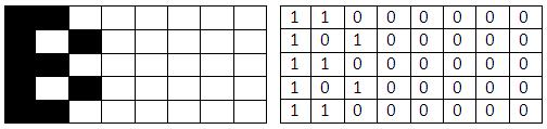
For clarity, consider an example of a sprite and its coding. Take an 8x5 sprite.
We
С0 A0 С0 A0 С0get the following set of bytes: To make it completely clear, take another 1 sprite 8x8.
The sprite will occupy 8 bytes and will have the following structure: The
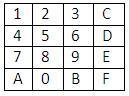
С0 60 30 18 0С 06 03keyboard for CHIP-8 is 16th and has the following appearance: You
can only argue and reason about the convenience and appropriateness of such a keyboard. But we will not depart from the original, because everything was developed specifically for such a keyboard.
Command system
It should be said right away that we will designate the address as NNN, KK - 8 bit constant, X and Y - 4 bit constants.
Now consider the list of commands.
0NNN Syscall nnn Call machine instruction instruction for processor 1802 with code NNN.
00CN * scdown n Scroll the screen down N lines.
00FB * Scright Scrolling the screen 4 pixels to the right
00FC * Scleft Scrolling the screen 4 pixels to the left
00FD * Exit the emulator
00FE * Low Set the graphic mode CHIP-8 (64x32)
00FF * High Set the graphic mode SUPER CHIP (128x64)
00E0 Cls Clear the screen
00EE Rts Return from routine
1NNN jmp nnn Transfer program execution to address NNN
2NNN jsr nnn Call a function at NNN. The previous address is pushed onto the stack.
3XKK skeq vx, kk Skip the next instruction (2 bytes) if VX = KK
4XKK skne vx, kk Skip the next instruction (2 bytes) if VX <> KK
5XY0 skeq vx, vy Skip the next instruction if VX = VY
6XKK mov vx, kk Write KK to the VX register
7XKK add vx, kk Write VX + KK to the VX register (According to information from Wikipedia and other sources it does not affect the flag)
8XY0 mov vx, vy Write the value of the register VY to
VX 8XY1 or vx, vy VX = VX OR VY.
8XY2 and vx, vy VX = VX AND VY
8XY3 xor vx, vy VX = VX XOR VY (undocumented in the original documents)
8XY4 add vx, vy VX = VX + VY. In VF = carry.
8XY5 sub vx, vy VX = VX - VY. (*) VF = NOT borrow.
8X06 shr vx VX = VX SHR 1 (VX = VX / 2), VF = carry
8XY7 sub vy, vx VX = VY - VX, VF = not borrow (*) (not documented in the original documents)
8XYE shl vx VX = VX SHL 1 (VX = VX * 2), VF = carry
9XY0 skne vx, vy Skip the following instruction if VX <> VY
ANNN mov I, nnn I = NNN
BNNN Jmi NNN Transfer program execution to NNN + V0
CXKK Rand vx, kk VX = (random number 0..255) AND KK
DXYN Draw vx, vy, n Draw a sprite of height N (for N = 0, consider N = 16) and a width of 8 at coordinates (VX, VY) starting in memory at the address contained in register I .VF = collision.
EX9E Skpr vx Skip the following instructions if the VX key is pressed.
EXA1 Skup vx Skip the following instructions if the number key in the VX is not pressed.
FX07 Gdelay vx VX = Delay timer
FX0A Key vx We wait for the button to be pressed and add it to VX.
FX15 Sdelay vx Delay timer = VX
FX18 Ssound vx Sound timer = VX
FX1E Add I, vx I = I + VX
FX29 Font vx Put in the I address of the font sprite 4 x 5 hexadecimal characters contained in VX
FX33 Bcd vx Place BCD representation of VX in memory to the addresses I..I + 2. For example, if VX contains 4Fh, then 00h 07h 09h will be written in memory, i.e. decimal representation 4Fh
FX55 Save vx Saves registers V0 ... VX in memory starting at address I
FX65 Load vx Loads registers V0 ... VX from memory starting at I
FX75 * Ssave vx Saves V0 ... VX (X <8) to HP48 flags
FX85 * Sload vx Loads V0 ... VX (X <8) from HP48 flags
* - this means the command is relevant only for the SUPER CHIP interpreter.
(*): When VX - VY occurs, VF is set to the denial of the loan. This means that if VX is greater than or equal to VY, VF will be set to 01, because the loan = 0. If VX is less than VY, VF is set to 00, because the loan = 1.
Basic sprite preparation
Using a piece of paper and a pen, we outline the font sprites. You will get something like this set:
Using it, write down the bytes of the value of each sprite.
Principles of Emulation
It is believed that all emulation should take place in a cycle of approximately this type.
Repeat
// do emulation
Until quit_pr;
Here quit_pr is considered a sign of stopping the emulation, and can change not only outside, but also from inside the emulation.
One of the most important points to observe is compliance with the frequencies of the equipment and optimization. If it is incorrect to describe the emulation of even such a simple language as CHIP-8, you can get very low performance and extremely high CPU time, but the correct emulation will provide sufficient performance at minimal cost.
Using Delphi, I decided to develop a system emulation as a class and gave it the name “TCpu1802”, based on the model of the processor used inside this system. Consider the main run procedure for it.
procedure tcpu1802.run;
begin
delaytimer.Enabled: = true;
soundtimer.Enabled: = true;
drawtimer.Enabled: = true;
work: = true;
repeat
useopcode;
if cpumulty <> 0 then
if (round (cycle) mod (2)) = 0 then sleep (cpumulty);
application.ProcessMessages;
until work = false;
delaytimer.Enabled: = false;
soundtimer.Enabled: = false;
drawtimer.Enabled: = false;
end;
First, at startup, we activate two standard for CHIP-8 timers and one, entered independently, to redraw the screen. Cycle - a variable containing the current cycle of commands, the call of each command increases the cycle by one. Every second action we will try to pause the interpreter for cpumulty milliseconds. This is necessary so that speeding does not occur.
Soundtimer and Drawtimer timers have an interval of 17 milliseconds, that is, they operate at a frequency of 58.82 hertz, which is as close as possible to the original.
Drawtimer delay is set to 10 milliseconds. That is, on average, rendering will be performed every 3-4 commands of the interpreter. Allocation to the timer is done so as not to clog the process of executing the interpreter and allows using regular means to perform parallelization of processes.
Let's look at the list of variables that we need to complete the emulation itself:
keycode: byte; // code of the pressed key
memory: array [0..8191] of byte; // 8 kilobytes of RAM, allocated due to the location of the fonts
stack: array [0..255] of word; // stack
stacksize: byte; // current stack
scan videoarray: array [0..2047] of boolean; // video array
mask: array [0..2047] of boolean; // mask of the video array
Vreg: array [0..15] of byte; // - registers V0..VF
Ireg: word; // 2 byte address register
CodeSender: word; // location of the next opcode in memory
sound: boolean; // is the sound playing now?
According to the architecture, video memory is located in the same amount of RAM as everything else, however, constant reading and writing there, examining bytes and analyzing them, would take up a lot of processor resources and is impractical, however, assuming that some program can read something directly from there, if reading from that memory area occurs, we can simply call an additional procedure called mirrorvideomem, which allows us to write the current contents of the video memory there. Such a solution is effective, although it causes a slightly greater use of RAM. The mirrorstack procedure is similar.
procedure tcpu1802.mirrorvideomem;
var
i, j: integer;
tmp: byte;
begin
if (Ireg> = $ F00) and (Ireg <= $ FFF) then
begin
for i: = 0 to 255 do
begin
tmp: = 0;
for j: = 0 to 7 do
begin
if videoarray [i * j] then tmp: = tmp + 1;
tmp: = tmp shl 1;
end;
memory [$ F00 + i]: = tmp;
end;
end;
end;
procedure tcpu1802.mirrorstack;
var
n, i: integer;
begin
if (Ireg> = $ EA0) and (Ireg <= $ EFF) then
begin
if stacksize> 12 then n: = 11 else n: = stacksize-1;
for i: = 0 to n do
begin
memory [$ EFF-i * 2]: = stack [i] div 256;
memory [$ EFF-i * 2 + 1]: = stack [i] mod 256;
end;
end;
end;
Before writing a processor, you can notice that each command is conditionally divided into 4 sections of 4 bits. To work with them, the opcode data type was introduced (type opcode = array [0..3] of byte;).
I will not dwell on converting and reading the next data from memory, however, I will pay attention to the structure of the run procedure that performs emulation. For optimization purposes, it uses not “if then else”, but “case”, and moreover, a number of commands allow you to use them using assembler, which further speeds up the emulation. Here is an example of such a command:
if op [3] = 1 then
begin
tmp: = Vreg [op [1]];
tmp2: = Vreg [op [2]];
asm
mov ah, [tmp]
or ah, [tmp2];
mov [tmp], ah;
end;
Vreg [op [1]]: = tmp;
used: = true;
codesender: = codesender + 2;
end;
Now, having considered all the moments of emulation, you can write your own CHIP-8 emulation. I hope you enjoyed my article and it was useful. Thank you for reading.
Used articles:
A CHIP-8 / SCHIP emulator
By David WINTER (HPMANIAC)
Wikipedia
Module
source : source
It was for her that I received an invitation from the user nsinreal , for which many thanks to him.
The request not to consider as “copy-paste” the article that appeared an hour before the publication of this one, because it could not be sent. Please consider that we did not see each other's articles, due to the different contents of the modules and different approaches to emulation, thanks in advance.