Independent study of circuitry. Abstract automaton. Part 2
The article is written, compiled and compiled by Brotherofken . Thank you very much.
In the previous article I tried to state all the basic definitions and principles in order to make this article as clear as possible. Everything did not fit, so I strongly advise you to familiarize yourself with these files:
Basis , Basis2 , Minimization . Later in this article, I left some explanatory notes in italics.
In this article I will try to explain in an accessible language what an abstract automaton is, how it is represented. Since the theory of automata is full of mathematics and complicated, I will try to write in human language so that an unprepared reader can understand what is at stake.

Electronic digital circuits can be formally divided into 2 classes:
In other words, the first class is logic devices that process the input signal. The second elements have memory and respond to a signal depending on the data entered into them.
The machine will have to implement some functions that are set by the developer. It can be a simple adder, it can implement any micro-command of the processor, select words from RAM or engage in parsing of the expression.
In general terms, without going into details, an abstract automaton can be represented as follows: Or, if we go from an illustration to a mathematical description: A =
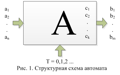
Designations:
δ and λ are not shown in the diagram for visual simplification.
Such an automaton operates discretely in time, that is, the values of the inputs, outputs and internal state of the automaton change at discrete time instants.
So, we have described in general terms what is an Abstract automaton. An example of such an automaton may be a trigger, a computer register, or an adder.
There are 2 types of machines:
As you can see the state of the automaton c (t) at the current time is a function of its state at the previous time and the input signal .
Automata differ in the type of output function. In the Miles machine, the output signal is determined by the input signal a (t) and the state of the machine at the previous moment in time c (t-1). The output signal of the Moore automaton is determined by a pair of input signal a (t) and the current state c (t).
It can also be noted that from one type it is possible to pass to the second and vice versa, moreover, when passing from the Miley automaton to the Moore automaton, the number of internal states of the automaton will remain the same, and with the reverse transition, the number of internal states can increase. We will not dwell on this in detail, believing that we have synthesized (drawn a graph) an automaton of the type that is needed.
So, this is over with the materiel. Let's try to describe the machines.
Those. a Miles-type machine generates an output signal when it changes its input, depending on its previous state. Moreover, the duration of the output signal does not depend on the duration of the input, but only on its presence. In Moore type machines, the output signal depends on the state of the machine at the current time i.e. the machine will generate a specific output signal until it changes its state.
As we found out in the first part, an automaton is a combination of input and output alphabets, a set of internal states and functions that determine transitions and outputs. However, usually the functions δ and λ are not defined, and the behavior of the automaton has to be described differently.
There are two main ways to specify an automaton:
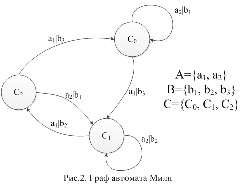
An automaton graph is a directed connected graph whose vertices symbolize the internal states of the automaton, and arcs are transitions from one state to another. For Count Miles, similar and output letters are indicated on the arcs. The output letters are written over the arcs, symbolizing that the output state depends on the state of the automaton at the previous moment in time. For a graph of the Moore automaton, only input letters are written on the arcs, while the output letters are indicated near the vertices. An important point: If as many arcs come out from each vertex as there are input letters, then the automaton is called complete . In other words, if transitions for each input letter are defined from each vertex. In our examples, the Miley machine is full , and the Moore machine is partial

.
And one more thing: If there is more arcs from one vertex than input letters (that is, 2 or more arcs with the same input letters), then such an automaton is called non-deterministic . This can happen when constructing a formalized description and then it will be necessary to make a transition to a deterministic automaton, but this cannot always be done. I also miss the description of this process by immediately drawing a deterministic automaton.
That's all about graphs.
Graphs are clearer for a person, and tables are for a machine. Any machine can be represented in the form of a table of transitions and outputs (TPV). In TPV, the rows are the internal states of the automaton, and the columns are the input letters.
We will build TPV for our counts Miles and Moore. If no input or output letter is defined, a dash is used instead. If no state is defined, then this same simple rule applies.
In TPV Miles, transitions and outputs are recorded in each cell. For example, if the machine is in state C0 and the letter a1 arrives at the input, then it will go into state C1 and the letter b3 will appear at the output.
For Count Moore, a marked transition table is built. An extra column for output letters is highlighted.
In the cell under the input letter it is written into what state the machine goes into, in the rightmost cell - which output letter it returns.
Using abstract automata, you can describe almost anything. You can describe the operation of a digital circuit, or you can describe a parser or lexical analyzer. Let's try to describe a trigger - why not an automaton?
To set a graph, you need a verbal description of the trigger algorithm. We read: We
encode the input and output alphabets:
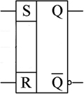
A = {a0, a1}, where a0 is the logical 1 at the input R, a1 is the logical unit at the input S.
B = {b0, b1}, where b0 is the logical 0 at the output Q, b1 is the logical unit at the output of Q.
We build the graph of the Miles automaton: Here is such a funny cheburashka turned out :-). Now you can build a transition and exit table:


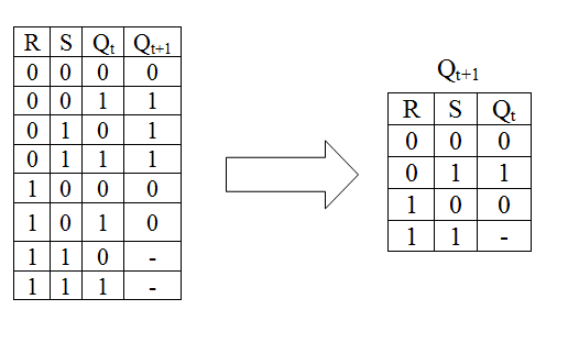
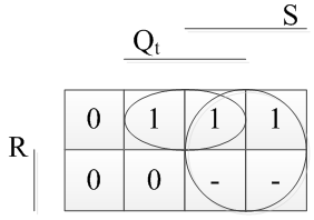
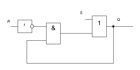
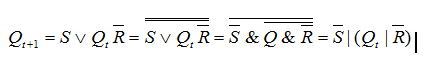
If we paint this table by converting the conventions into actual ones, we get a table that is a trigger transition table. Then it can be simplified: We apply the resulting function to the Veitch map and minimize it: Write out what happened: Build the circuit according to the function (Did you do your homework?): It's a little unusual to see a trigger in a Boolean basis, so we transfer the function to the NAND basis and draw the circuit in him: And on the diagram, an asynchronous RS trigger is indicated like this: Now if you apply a little effort, you can independently synthesize a simple New Year's garland.


In the previous article I tried to state all the basic definitions and principles in order to make this article as clear as possible. Everything did not fit, so I strongly advise you to familiarize yourself with these files:
Basis , Basis2 , Minimization . Later in this article, I left some explanatory notes in italics.
In this article I will try to explain in an accessible language what an abstract automaton is, how it is represented. Since the theory of automata is full of mathematics and complicated, I will try to write in human language so that an unprepared reader can understand what is at stake.
Electronic digital circuits can be formally divided into 2 classes:
- Combination Schemes (CS) - do not have memory. The output signal is generated depending on the combination of input data at a fixed point in time (taking into account the delay in signal conversion). Combination schemes, their types and construction principles can be a topic for a separate article, and as examples we can cite: Controlled buses, multiplexers and demultiplexers, decoders and encoders, code converters, combinational counters and adders, etc.
- Schemes with memory - the algorithm of their operation depends on the state of the inputs and memory (what was at previous times). These schemes are described using the theory of finite automata. Speech about them will go further.
In other words, the first class is logic devices that process the input signal. The second elements have memory and respond to a signal depending on the data entered into them.
Abstract automaton
The machine will have to implement some functions that are set by the developer. It can be a simple adder, it can implement any micro-command of the processor, select words from RAM or engage in parsing of the expression.
In general terms, without going into details, an abstract automaton can be represented as follows: Or, if we go from an illustration to a mathematical description: A =
Designations:
- The set {A} - represents the set of values on the physical inputs of the automaton. At the input in our case there will be some sequence of high and low voltage levels that will encode logical zeros and ones.
- The set {B} - represents the set of values at the physical outputs of the automaton.
- The set {C} - and the set that represents the internal state of the automaton - memory. For the future, C0 will denote the initial state of the automaton.
- δ = X × Z → Z are the transition functions of the automaton; they uniquely determine the state ai into which the automaton passes from the state aj.
- λ = X × Z → Y are the functions of the outputs, they determine what is on the output of the machine, depending on the inputs and the internal state.
δ and λ are not shown in the diagram for visual simplification.
Such an automaton operates discretely in time, that is, the values of the inputs, outputs and internal state of the automaton change at discrete time instants.
So, we have described in general terms what is an Abstract automaton. An example of such an automaton may be a trigger, a computer register, or an adder.
There are 2 types of machines:
- Automatic Miles. It is described by the system of equations:
c (t) = δ (a (t), c (t-1));
b (t) = λ (a (t), c (t-1)). - Moore assault rifles. It is described by the equations:
c (t) = δ (a (t), c (t-1));
b (t) = λ (a (t), c (t)).
As you can see the state of the automaton c (t) at the current time is a function of its state at the previous time and the input signal .
Automata differ in the type of output function. In the Miles machine, the output signal is determined by the input signal a (t) and the state of the machine at the previous moment in time c (t-1). The output signal of the Moore automaton is determined by a pair of input signal a (t) and the current state c (t).
It can also be noted that from one type it is possible to pass to the second and vice versa, moreover, when passing from the Miley automaton to the Moore automaton, the number of internal states of the automaton will remain the same, and with the reverse transition, the number of internal states can increase. We will not dwell on this in detail, believing that we have synthesized (drawn a graph) an automaton of the type that is needed.
So, this is over with the materiel. Let's try to describe the machines.
Those. a Miles-type machine generates an output signal when it changes its input, depending on its previous state. Moreover, the duration of the output signal does not depend on the duration of the input, but only on its presence. In Moore type machines, the output signal depends on the state of the machine at the current time i.e. the machine will generate a specific output signal until it changes its state.
Ways to set automata
As we found out in the first part, an automaton is a combination of input and output alphabets, a set of internal states and functions that determine transitions and outputs. However, usually the functions δ and λ are not defined, and the behavior of the automaton has to be described differently.
There are two main ways to specify an automaton:
- Using graphs.
- Using transition and exit tables.
Counts
An automaton graph is a directed connected graph whose vertices symbolize the internal states of the automaton, and arcs are transitions from one state to another. For Count Miles, similar and output letters are indicated on the arcs. The output letters are written over the arcs, symbolizing that the output state depends on the state of the automaton at the previous moment in time. For a graph of the Moore automaton, only input letters are written on the arcs, while the output letters are indicated near the vertices. An important point: If as many arcs come out from each vertex as there are input letters, then the automaton is called complete . In other words, if transitions for each input letter are defined from each vertex. In our examples, the Miley machine is full , and the Moore machine is partial
.
And one more thing: If there is more arcs from one vertex than input letters (that is, 2 or more arcs with the same input letters), then such an automaton is called non-deterministic . This can happen when constructing a formalized description and then it will be necessary to make a transition to a deterministic automaton, but this cannot always be done. I also miss the description of this process by immediately drawing a deterministic automaton.
That's all about graphs.
Transition and exit tables.
Graphs are clearer for a person, and tables are for a machine. Any machine can be represented in the form of a table of transitions and outputs (TPV). In TPV, the rows are the internal states of the automaton, and the columns are the input letters.
We will build TPV for our counts Miles and Moore. If no input or output letter is defined, a dash is used instead. If no state is defined, then this same simple rule applies.
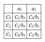
TPV Count Miles
In TPV Miles, transitions and outputs are recorded in each cell. For example, if the machine is in state C0 and the letter a1 arrives at the input, then it will go into state C1 and the letter b3 will appear at the output.
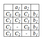
TPV Count Moore
For Count Moore, a marked transition table is built. An extra column for output letters is highlighted.
In the cell under the input letter it is written into what state the machine goes into, in the rightmost cell - which output letter it returns.
Automation synthesis example
Using abstract automata, you can describe almost anything. You can describe the operation of a digital circuit, or you can describe a parser or lexical analyzer. Let's try to describe a trigger - why not an automaton?
To set a graph, you need a verbal description of the trigger algorithm. We read: We
encode the input and output alphabets:
A = {a0, a1}, where a0 is the logical 1 at the input R, a1 is the logical unit at the input S.
B = {b0, b1}, where b0 is the logical 0 at the output Q, b1 is the logical unit at the output of Q.
We build the graph of the Miles automaton: Here is such a funny cheburashka turned out :-). Now you can build a transition and exit table:
If we paint this table by converting the conventions into actual ones, we get a table that is a trigger transition table. Then it can be simplified: We apply the resulting function to the Veitch map and minimize it: Write out what happened: Build the circuit according to the function (Did you do your homework?): It's a little unusual to see a trigger in a Boolean basis, so we transfer the function to the NAND basis and draw the circuit in him: And on the diagram, an asynchronous RS trigger is indicated like this: Now if you apply a little effort, you can independently synthesize a simple New Year's garland.