Weather Station (Arduino pro mini, BME280, LCD1602)
Introduction
What can be displayed on a two-line screen other than “Hello world!”? Why not display temperature humidity and pressure?
The sensors offered as an arduino training aid (DHT11, DHT22) show temperature and humidity. For educational purposes (for the university), it was necessary to observe the pressure in the same way. Naturally, the department has a barometer, but why not collect your own? In addition, you can further accumulate readings in automatic mode, and this is a good experience in learning arduino.
One way or another, components were ordered from China and this device was assembled.
Necessary components for
Arduino Pro Mini
I2C for LCD (you could order it immediately, but it turned out a little cheaper)
LCD 1602
BME280
USB-UART was used to send the sketch to arduino . It was also possible to use a Raspberry Pi or a computer with a COM port.
Connection diagram for firmware and program code
From China, USB-UART came with a set of wiring:
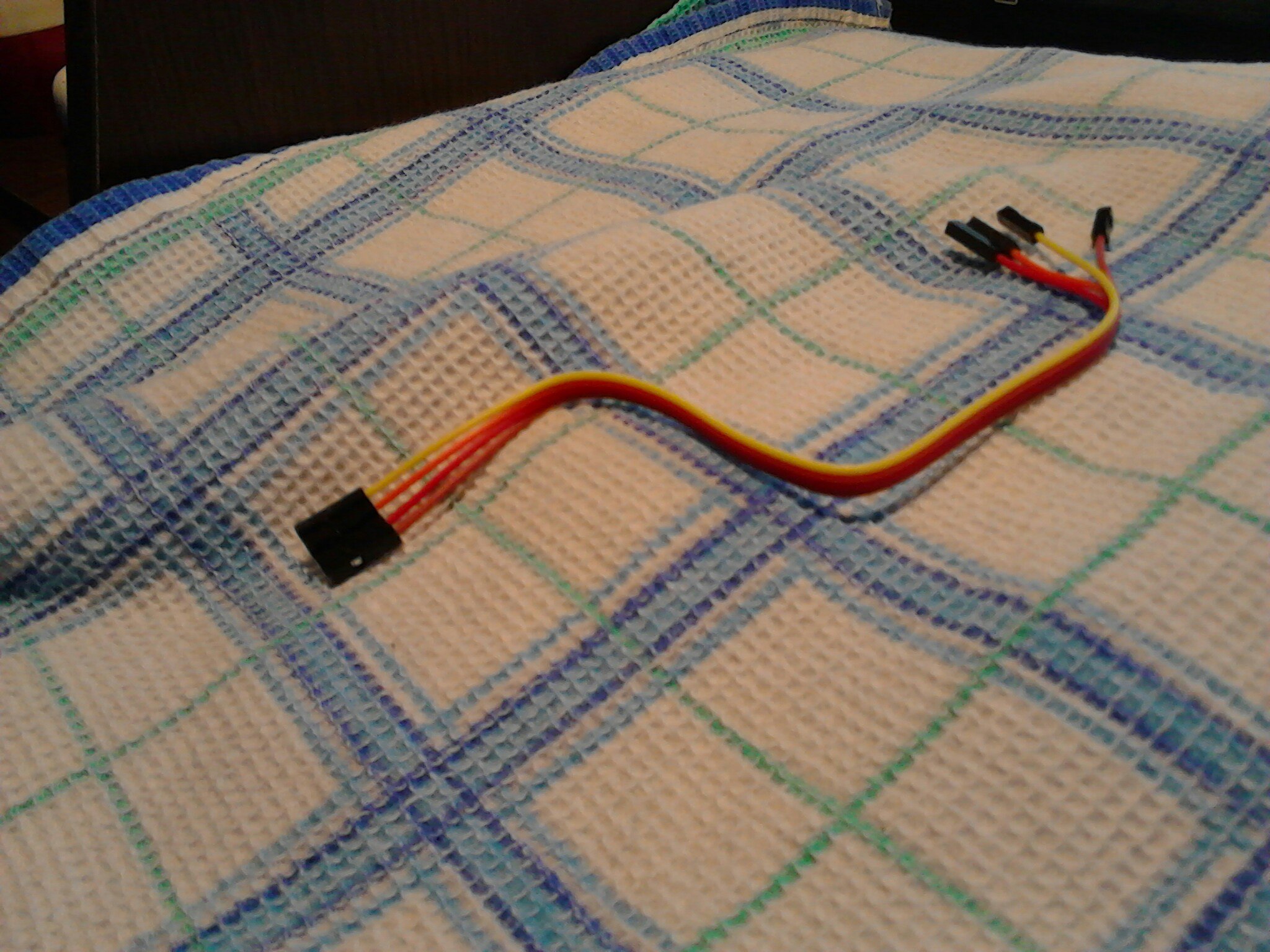
They were enough. I left the jumper at 3.3 volts, despite the fact that my version of the arduino is powered by 5 volts.
UART - Arduino
5v - VCC
TXD - RXD
RXD - TXD
GND - GND
CTS - DTR (optional, it didn’t work for me, maybe because the signal voltage remained 3.3V)
If you do not connect the DTR, then after sending the arduino firmware you need to reboot with the built-in button, active data exchange will begin on both sides (as indicated by the USB-UART LEDs), after the firmware is downloaded successfully, it will reboot itself.
Required third-party libraries:
SparkFunBME280
LiquidCrystal I2C
Directly the code, with comments from the examples (in case someone needs to change something).
The sensor address can be guessed, there are only two of them.
How to find out the address of your display, you can see here . Depending on the chip, there are two plates.
In this case:

And the address will be 0x3F since A0 - A2 open: The
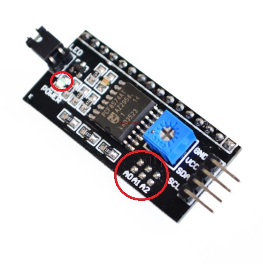
LED that is circled in the oval isbetter to unsolder.
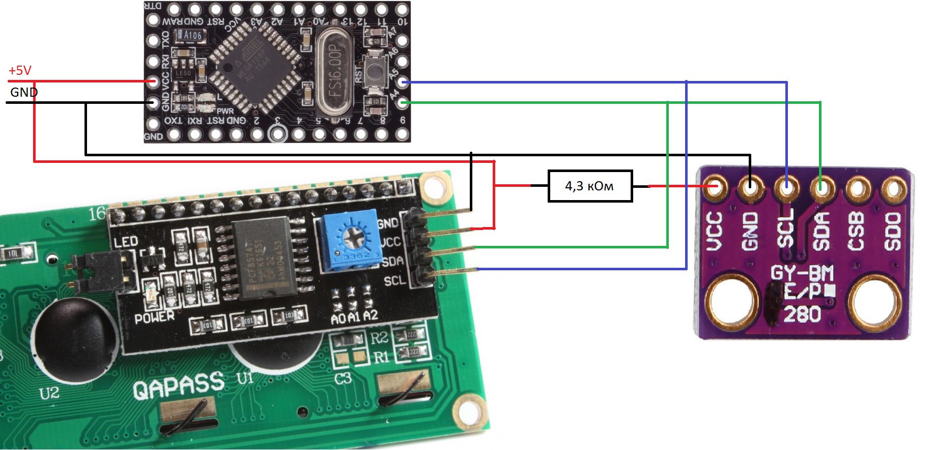
Connection scheme The
resistor was selected as half of the sensor resistance (between VVC and GND) so that the voltage drop across it was 1.7 volts. Also, the circuit can be powered from the input of RAW, other voltage (for example from the crown).
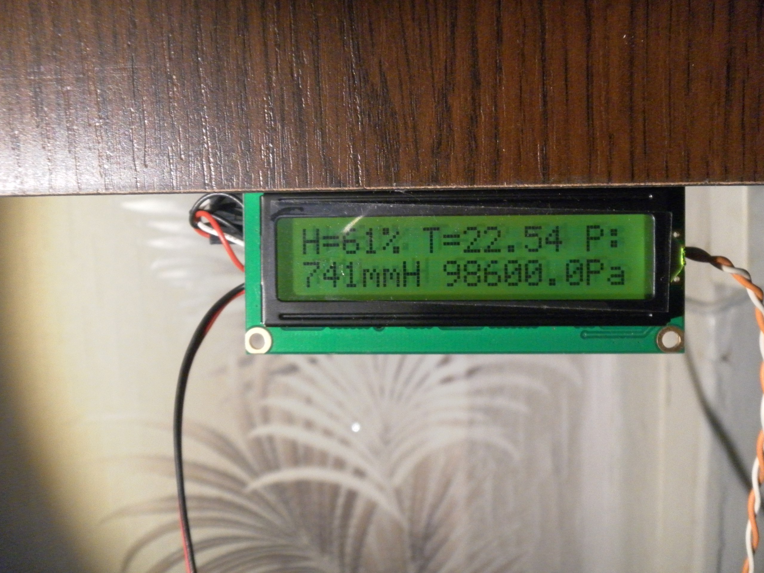
The photo shows that for compactness, you can take power to the sensor and display from another pin. It also shows a branch of an orange-yellow pair of wires, a resistor of 100 Ohms hangs on them to reduce the brightness of the backlight (you can leave the jumper, but it will cut your eyes).
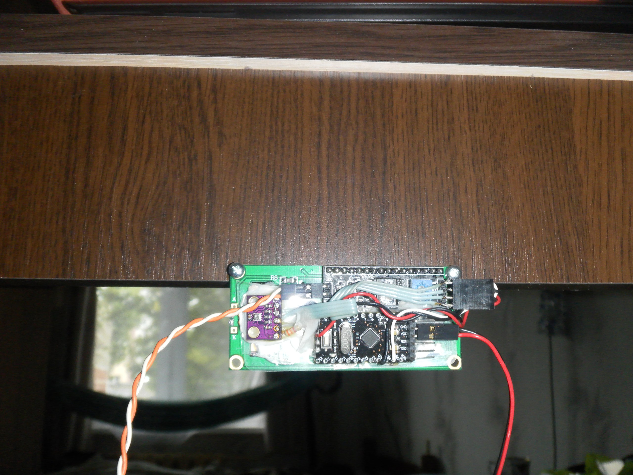
In my case, everything is powered by an old computer power supply. Can be powered by USB. All components were glued with Moment glue, which was at hand.
Summary
In the workplace appeared 1602 bolted to the table, which shows pressure, humidity, temperature. Arduino can be reflashed without removing (it may become a creeping line ).
What can be displayed on a two-line screen other than “Hello world!”? Why not display temperature humidity and pressure?
The sensors offered as an arduino training aid (DHT11, DHT22) show temperature and humidity. For educational purposes (for the university), it was necessary to observe the pressure in the same way. Naturally, the department has a barometer, but why not collect your own? In addition, you can further accumulate readings in automatic mode, and this is a good experience in learning arduino.
One way or another, components were ordered from China and this device was assembled.
Necessary components for
Arduino Pro Mini
I2C for LCD (you could order it immediately, but it turned out a little cheaper)
LCD 1602
BME280
USB-UART was used to send the sketch to arduino . It was also possible to use a Raspberry Pi or a computer with a COM port.
Connection diagram for firmware and program code
From China, USB-UART came with a set of wiring:
They were enough. I left the jumper at 3.3 volts, despite the fact that my version of the arduino is powered by 5 volts.
UART - Arduino
5v - VCC
TXD - RXD
RXD - TXD
GND - GND
CTS - DTR (optional, it didn’t work for me, maybe because the signal voltage remained 3.3V)
If you do not connect the DTR, then after sending the arduino firmware you need to reboot with the built-in button, active data exchange will begin on both sides (as indicated by the USB-UART LEDs), after the firmware is downloaded successfully, it will reboot itself.
Required third-party libraries:
SparkFunBME280
LiquidCrystal I2C
Directly the code, with comments from the examples (in case someone needs to change something).
The code
#include
#include "SparkFunBME280.h"
#include "Wire.h"
#include "SPI.h"
#include
//Global sensor object
BME280 mySensor;
LiquidCrystal_I2C lcd(0x3F,16,2); //Адрес дисплея, в моём случае 0x3F
void setup()
{
  lcd.init();
  lcd.backlight();
	//***Driver settings********************************//
	//commInterface can be I2C_MODE or SPI_MODE
	//specify chipSelectPin using arduino pin names
	//specify I2C address.  Can be 0x77(default) or 0x76
	//For I2C, enable the following and disable the SPI section
  mySensor.settings.commInterface = I2C_MODE;
  mySensor.settings.I2CAddress = 0x76; //Адрес датчика, в моём случае не стандартный
	//For SPI enable the following and dissable the I2C section
	//mySensor.settings.commInterface = SPI_MODE;
	//mySensor.settings.chipSelectPin = 10;
	//***Operation settings*****************************//
	//renMode can be:
	//  0, Sleep mode
	//  1 or 2, Forced mode
	//  3, Normal mode
	mySensor.settings.runMode = 3; //В примере предлагают использовать Forced mode, но при обновлении раз в секунду достаточно Normal mode
	//tStandby can be:
	//  0, 0.5ms
	//  1, 62.5ms
	//  2, 125ms
	//  3, 250ms
	//  4, 500ms
	//  5, 1000ms
	//  6, 10ms
	//  7, 20ms
	mySensor.settings.tStandby = 5; //Очевидно чаще не нужно
	//filter can be off or number of FIR coefficients to use:
	//  0, filter off
	//  1, coefficients = 2
	//  2, coefficients = 4
	//  3, coefficients = 8
	//  4, coefficients = 16
	mySensor.settings.filter = 0;
	//tempOverSample can be:
	//  0, skipped
	//  1 through 5, oversampling *1, *2, *4, *8, *16 respectively
	mySensor.settings.tempOverSample = 1;
	//pressOverSample can be:
	//  0, skipped
	//  1 through 5, oversampling *1, *2, *4, *8, *16 respectively
    mySensor.settings.pressOverSample = 1;
	//humidOverSample can be:
	//  0, skipped
	//  1 through 5, oversampling *1, *2, *4, *8, *16 respectively
	mySensor.settings.humidOverSample = 1;
	//Calling .begin() causes the settings to be loaded
	mySensor.begin();
}
void loop()
{
  //Буквы можно вывести один раз, а далее менять показания, но показания при изменении количества значащих цифр могут сдвигать строку.
  lcd.setCursor(0,0);
  lcd.print("H=");
  lcd.print((uint8_t)mySensor.readFloatHumidity());
  lcd.print("%");
  lcd.print(" T=");
  lcd.print(mySensor.readTempC());
  lcd.setCursor(13,0);
  lcd.print(" P:");
  lcd.setCursor(0,1);
  int mmH=mySensor.readFloatPressure()/133;
  lcd.print(mmH);
  lcd.print("mmH ");
  lcd.print(mySensor.readFloatPressure());
  lcd.setCursor(14,1);
  lcd.print("Pa");
  delay(1000);
}
The sensor address can be guessed, there are only two of them.
How to find out the address of your display, you can see here . Depending on the chip, there are two plates.
In this case:
And the address will be 0x3F since A0 - A2 open: The
LED that is circled in the oval is
Connection scheme The
resistor was selected as half of the sensor resistance (between VVC and GND) so that the voltage drop across it was 1.7 volts. Also, the circuit can be powered from the input of RAW, other voltage (for example from the crown).
The photo shows that for compactness, you can take power to the sensor and display from another pin. It also shows a branch of an orange-yellow pair of wires, a resistor of 100 Ohms hangs on them to reduce the brightness of the backlight (you can leave the jumper, but it will cut your eyes).
In my case, everything is powered by an old computer power supply. Can be powered by USB. All components were glued with Moment glue, which was at hand.
Summary
In the workplace appeared 1602 bolted to the table, which shows pressure, humidity, temperature. Arduino can be reflashed without removing (
A photo
Workplace, general view.
Front view.
Back view.
Workplace, general view.
Front view.
Back view.