Electron microscope in the garage. High voltage
In the very first article I wrote a rough plan of our series, the final point of which is work with electronics. It's time to go to him. Everything else is undermined, leaks are found and fixed, the vacuum system is polished to a mirror finish.
From electronics for experiments we have:
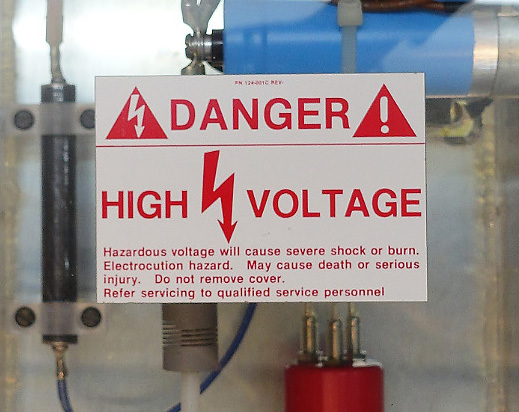
Of the large, independent devices, there is a high-voltage power supply from an Amray microscope of about 1990, an unknown working capacity, with signs of repair by a Russian-speaking person.
We need to figure out how to control it, how to connect it to our column and, in general, check if it works. And then suspiciously there inside everything is signed in Russian with a marker :)
A small video for those who are more interested to see everything "live", to see how the cathode is burning inside the microscope, and all this as quickly as possible :)
High Voltage Power Supply consists of two parts.
Stabilized, controlled, powerful enough, specially designed for electron microscopes - it's all about him. Miracle of the 1990s, which is still produced by a single American company. Power supply - 110 V, frequency 60 Hz. To my official question “will it work from 110 V 50 Hz”, sent a month ago, the company did not consider it necessary to answer.

On the right below, as well as everywhere inside, you can see those very traces of stay. Most likely, this device broke down and was repaired. How successful was the repair - remains to be seen.
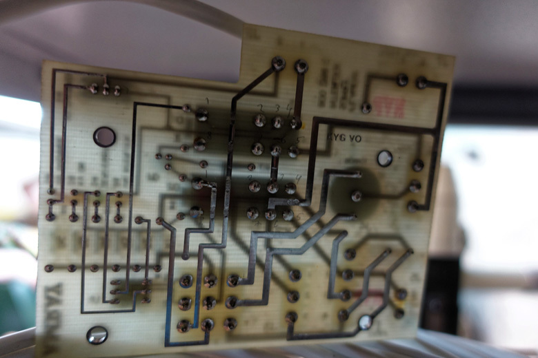
The board lying on it, and "was bundled with this power supply. There are no problems with it. Firstly, it is also carefully signed by a marker, where there is +5 V, and where is 10 V. Secondly, the essence of it was relatively easy to understand.
This voltage source is controlled by an analog signal. It itself provides a reference voltage of 10 V, which corresponds to -30kV at the output. Therefore, Amray engineers made a simple solution. They put a 12-bit (bit) digital-to-analog converter (DAC) , from which only 9 bits were used to control as separate conductors, and 5 V power supply for a DAC. Total output voltage levels, which corresponds to the step in
  V.
V.
But the engineers went further, and made each bit a galvanic isolation using optocouplers (these are the same nine microcircuits on the board).
It remains only to connect these bits to the microcontroller, using its GPIO outputs, and you can select the accelerating voltage directly from the control computer.
While I did not do this, I simply connected them to 5 V (which corresponds to a logical unit, and the pull-up resistors are already there, pull-up to zero).
When you turn on the network you can hear that the unit beeps, i.e. something happens there. I do not have a high-voltage voltmeter, what should I do?
The first idea is to try it “qualitatively”, i.e. does it generate enough powerful and high voltage at all. We pump out forevacuum, connect to the same wire as in the video about high-voltage discharges in vacuum.
And here is the result:
There is a discharge, the power supply is turned off by overload, then it turns on again.
Once the high voltage it generates, then I want to analyze it “quantitatively”, or, more simply, measure the output voltage.
I thought about the voltage divider , dug through all the stocks ofradio components of passive electronic components, more precisely, megohm resistors.
Found a little green.

But even at the most current maximum divider need 30Mom. And in general, testing this source at maximum current is not an option.
I bought thirty 10W of 1W resistors and soldered one of these divisors:
Papers are attracted effectively, and the Soviet pointer device adds atmosphere.
But, the fact is that (and knowledgeable people honestly warned me about this), these resistors are designed for a maximum of 500 V. And in our case, the voltage drop on each is Q. As a result, for small values of voltages, it was possible to see that the adjustment works. With increasing voltage above 15kV, the breakdown begins in various places (the sound is audible), and it is no longer possible to get any reliable readings.
Resistors for a higher voltage were not at hand, but these were enough to make sure that the source produces a high voltage and allows it to be regulated, within certain limits.
We must go on!

A rather beautiful device, especially in comparison with oil-filled power units of old microscopes.
The aquarium has three main functions:
The difficulty lies in the fact that the entire cathode is under negative high voltage, and it is necessary to “mix” in the voltage required for the heating of the cathode. In those days, it was apparently not fashionable to make switching power supplies, so there was made a variable transformer driven by a motor, and a huge transformer for mixing this voltage into the high-voltage part.
The bias voltage of the Venelt cylinder is changed by rotating the variable resistor (the simplest implementation, since special accuracy is not required there).
But with the socket there was a difficulty - it is obviously not at all from this microscope. But, having a lathe and milling machine, as well as desire, enthusiasm and a free evening, this task turns from a problem into a pleasure.
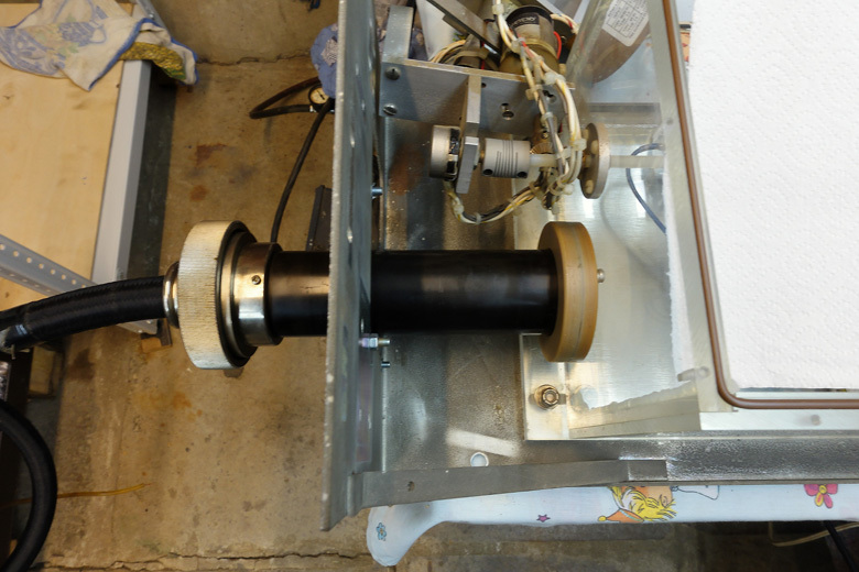
On the first videoThis article shows how this happened.
Well, now the matter is small - to heat the cathode in its place, turn on the high voltage and watch the emission of free electrons.
But, there is one more unsolved element. In the aquarium there is a fee that should manage this all. The problem is that all connectors are disconnected, there is no documentation.

I managed to guess where to connect a variable cathode filament transformer (in fact, this connector is the only one that obviously fit) and an input transformer in the high-voltage part (there the connector numbers differed by one, probably the extension cable was). For the rest, I am not sure, and the algorithm of operation is strange: one relay on self-pickup through an optocoupler, the second is simply controlled from the connector. From the tips there are only a few labels on the board.
Can you tell me some fresh ideas?
From 11 to 13 April, VacuumTechExpo will be held in Moscow in Sokolniki (admission is free, provided you attend to the electronic ticket in advance).
Communication can be held via Telegram: @Fireballrus
Thank you for reading, always happy to read your comments on both the article and the video .
In the next series - the electron beam! :)
From electronics for experiments we have:
- various microcontrollers (popular boards Arduino Nano, Due, less popular, but interesting Stellaris Launchpad; single-board computers Raspberry Pi 3 B + and Intel Edison)
- ADC (AD7715, ADS7816) and DAC (DAC8512)
- Op amps, precision and low noise
- The rest of the electronic components on the little things, as well as "donor" devices (failed ATX power supplies, UPS, CD-ROM drives, etc.)
Of the large, independent devices, there is a high-voltage power supply from an Amray microscope of about 1990, an unknown working capacity, with signs of repair by a Russian-speaking person.
We need to figure out how to control it, how to connect it to our column and, in general, check if it works. And then suspiciously there inside everything is signed in Russian with a marker :)
A small video for those who are more interested to see everything "live", to see how the cathode is burning inside the microscope, and all this as quickly as possible :)
High Voltage Power Supply consists of two parts.
- Controlled high voltage source from 0 to -30kV
- Aquarium
I. High voltage source
Stabilized, controlled, powerful enough, specially designed for electron microscopes - it's all about him. Miracle of the 1990s, which is still produced by a single American company. Power supply - 110 V, frequency 60 Hz. To my official question “will it work from 110 V 50 Hz”, sent a month ago, the company did not consider it necessary to answer.
On the right below, as well as everywhere inside, you can see those very traces of stay. Most likely, this device broke down and was repaired. How successful was the repair - remains to be seen.
The board lying on it, and "was bundled with this power supply. There are no problems with it. Firstly, it is also carefully signed by a marker, where there is +5 V, and where is 10 V. Secondly, the essence of it was relatively easy to understand.
This voltage source is controlled by an analog signal. It itself provides a reference voltage of 10 V, which corresponds to -30kV at the output. Therefore, Amray engineers made a simple solution. They put a 12-bit (bit) digital-to-analog converter (DAC) , from which only 9 bits were used to control as separate conductors, and 5 V power supply for a DAC. Total
output voltage levels, which corresponds to the step in V. But the engineers went further, and made each bit a galvanic isolation using optocouplers (these are the same nine microcircuits on the board).
It remains only to connect these bits to the microcontroller, using its GPIO outputs, and you can select the accelerating voltage directly from the control computer.
While I did not do this, I simply connected them to 5 V (which corresponds to a logical unit, and the pull-up resistors are already there, pull-up to zero).
When you turn on the network you can hear that the unit beeps, i.e. something happens there. I do not have a high-voltage voltmeter, what should I do?
The first idea is to try it “qualitatively”, i.e. does it generate enough powerful and high voltage at all. We pump out forevacuum, connect to the same wire as in the video about high-voltage discharges in vacuum.
And here is the result:
There is a discharge, the power supply is turned off by overload, then it turns on again.
Once the high voltage it generates, then I want to analyze it “quantitatively”, or, more simply, measure the output voltage.
I thought about the voltage divider , dug through all the stocks of
Found a little green.
But even at the most current maximum divider need 30Mom. And in general, testing this source at maximum current is not an option.
I bought thirty 10W of 1W resistors and soldered one of these divisors:
Papers are attracted effectively, and the Soviet pointer device adds atmosphere.
But, the fact is that (and knowledgeable people honestly warned me about this), these resistors are designed for a maximum of 500 V. And in our case, the voltage drop on each is
Q. As a result, for small values of voltages, it was possible to see that the adjustment works. With increasing voltage above 15kV, the breakdown begins in various places (the sound is audible), and it is no longer possible to get any reliable readings. Resistors for a higher voltage were not at hand, but these were enough to make sure that the source produces a high voltage and allows it to be regulated, within certain limits.
We must go on!
Ii. Aquarium
A rather beautiful device, especially in comparison with oil-filled power units of old microscopes.
The aquarium has three main functions:
- Cathode Filament Adjustment
- Management of the first electrostatic lens (Weneltht cylinder)
- Directly applying voltage to the microscope
The difficulty lies in the fact that the entire cathode is under negative high voltage, and it is necessary to “mix” in the voltage required for the heating of the cathode. In those days, it was apparently not fashionable to make switching power supplies, so there was made a variable transformer driven by a motor, and a huge transformer for mixing this voltage into the high-voltage part.
The bias voltage of the Venelt cylinder is changed by rotating the variable resistor (the simplest implementation, since special accuracy is not required there).
But with the socket there was a difficulty - it is obviously not at all from this microscope. But, having a lathe and milling machine, as well as desire, enthusiasm and a free evening, this task turns from a problem into a pleasure.
On the first videoThis article shows how this happened.
Well, now the matter is small - to heat the cathode in its place, turn on the high voltage and watch the emission of free electrons.
But, there is one more unsolved element. In the aquarium there is a fee that should manage this all. The problem is that all connectors are disconnected, there is no documentation.
I managed to guess where to connect a variable cathode filament transformer (in fact, this connector is the only one that obviously fit) and an input transformer in the high-voltage part (there the connector numbers differed by one, probably the extension cable was). For the rest, I am not sure, and the algorithm of operation is strange: one relay on self-pickup through an optocoupler, the second is simply controlled from the connector. From the tips there are only a few labels on the board.
Can you tell me some fresh ideas?
Meeting in Moscow
From 11 to 13 April, VacuumTechExpo will be held in Moscow in Sokolniki (admission is free, provided you attend to the electronic ticket in advance).
Communication can be held via Telegram: @Fireballrus
Thank you for reading, always happy to read your comments on both the article and the video .
In the next series - the electron beam! :)
Only registered users can participate in the survey. Sign in , please.
Do you have interest to meet at the exhibition?
- 4% Yes, 11 April 8
- 3% Yes, April 12th 6
- 22.3% No, thanks, articles and videos are enough 44
- 70.5% Yes, but there is no possibility to come 139