Electron microscope in the garage. Black vacuum
If you missed previous issues - be sure to read .
Forvacuum in the microscope turned out to be a very motivating factor for continuing the work :) After all, the most interesting thing is to get a high vacuum and run an electron-beam system!
To do this, you need to revive the diffusion (steam oil) pump . It lacks one important part - the heater, but otherwise it is serviceable, and even some amount of native vacuum oil, called working fluid, remains in it .
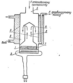 Let me remind you that the diffusion pump works according to a very simple scheme. Inside is poured oil, which is heated by a heater. When it starts to boil (about 180-200 degrees Celsius), its vapors exit through special nozzles inside the pump at supersonic speeds and condense on the walls, which are specially cooled from the outside. Along the way, the molecules of the oil collide with the gas molecules and thus move them closer to the inlet of the foreline pump.
Illustration from the book by N.G.Sushkin . Electron microscope. M., 1949. At that time, it was considered normal to use mercury as a working fluid, and the book even presents a device for trapping mercury vapor. But much has been written about the merits of special vacuum oils.
I didn’t succeed in finding a special heater for the pump, so I had an idea to make the improvised means, at the same time utilizing unnecessary equipment.
My eyes fell on the old KRUPS drip coffee maker, which was bought back in the distant 90s (it was made in Germany, and not China, like most household appliances now) and honestly worked for about twenty years. The basis of making coffee in this type of coffee maker is the boiling tube, which is combined with the heater of the finished drink in the form of a burner.
I disassembled it and saw a high-quality heating element for 1000 W, filled with silumin, and even with a hole in the middle through which it can be fastened to a diffnasos!
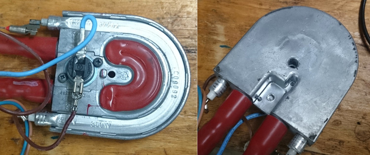
In the photo on the right you can see that the surface is not very smooth and is adjacent to the plane only at a few points. This needs to be corrected, and the frezer with the “fly” cutter will help in this.
Caution, a loud sound (it is in reality just as loud) and a first-person view!
Done, put the heater on the diffusion pump without removing it from the microscope. The compound missed the KPT-8 paste and also placed a thermocouple there to monitor the temperature.
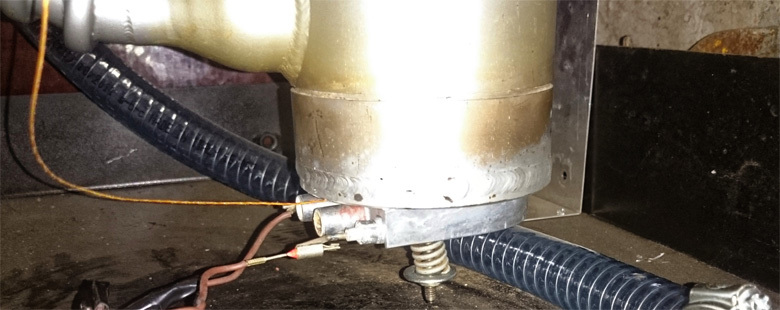
Bottom he tightened with a spring to prevent deformations from thermal expansion. At the time of the experiment, the vacuum hose was blocked from temperature radiation, so everything is fine with it. It did not become normal with another :)
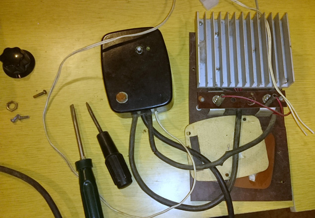
Since the heater of the coffee maker has a power of 1 kW, and the pump is designed for 600W, it will not be very good to simply turn on the heater in the network. Then I remembered a device manufactured by the Soviet industry under the name Power regulator electronic RME 100/220 .
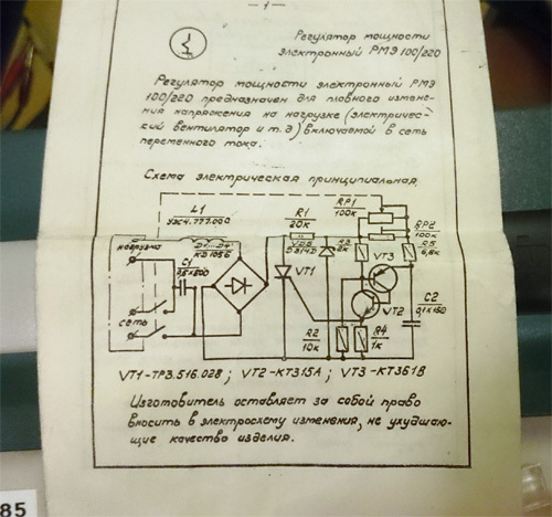
This is the most common thyristor regulator , which is widely used in dimmers (although now there are other schemes).
The principle of operation is very simple: the control element (thyristor) turns on with a delay, and therefore part of the sinusoid AC is clipped. This can be clearly seen on the oscillogram:

According to the instructions, the maximum load connected to RME 100/220 is 100 W. Fortunately, about 30 years ago, my father had already upgraded one such RME: he assembled a diode bridge of powerful diodes on a separate large radiator and put a powerful thyristor there too. It was not necessary to change the control circuit, it did not warm up at all.
Surprisingly, this piece was quickly found (it was one of the elements of executive automation, which worked until about 1990), but after switching on, a problem was discovered - the power was almost not regulated. I checked all the wires, cleaned everything from dust, finally began to solder and check all the elements step by step. Thyristor, three diodes from the diode bridge - everything is in order. Without any hope, I check the remaining, the last fourth diode, and it turns out to be broken! I am changing the same stock from my own and everything starts to work fine.
Externally, in the process of repairing it, it looked like this:
Since everything is there - then what to expect, let's go swing to a deep vacuum!
We connect the electrician, we connect running water to cool the diffusion pump (even if it pours out right on the street, there is no time to wait).
We turn on the fornasos, turn out the power regulator to the full, open all the valves (figs with it, that the oil vapors will get inside the column, there is everything in the oil, but I haven’t cleaned it yet), we look at the thermometer and the pressure sensor.
The temperature of the heater grows and grows, the paste begins to smoke, the pressure never drops. Warmed up the heater to 200 degrees, then cooled.
Does not shake. What to do ... Attached a thermocouple to another place - on the pump itself, to know what the temperature of the oil is, not the heater. He switched on again, started warming - with difficulty the temperature of the pump reached 100 degrees, the smoke from KPT-8 paste is already visible to the naked eye, all the doors are open, I air and warm further, the experiment still.
I looked, the temperature began to approach 180, and then suddenly the pressure suddenly changed - the pumping began. 7 * 10 ^ -4 Torr, 5 * 10 ^ -4 and already passed even to 9 * 10 ^ -5 Torr! Then it went slower (remember, the working pressure of the microscope is 5 * 10 ^ -5 Torr).
And then I, unsuspecting, decided to make a photo - share it with the other participants of the project, show success!
First of all, I was tense due to the fact that the heater glows red. It was not in my plans, but in controlling the temperature of the pump, everything was in order, 180-190 degrees Celsius. Of course, I immediately de-energized the heater, continuing to cool the diffusor, and continuing to evacuate (the pump warmed up, the oil boils, and continues to pump the vacuum) reached, by inertia, the working pressure of 5 * 10 ^ -5 Torr.
He continued to look at the picture, and noticed a large, beautifully shiny drop on it. It was a drop from that heater, which I milled so cheerfully on the video above ... I
cooled down, I cooled down myself for a few days (from anger, a joke :)), and took it apart again. The heater cannot be restored, everything has melted, including the heating element itself.
But what is the matter, why was there such a bad thermal contact? And the whole thing turned out to be trivial. The stud, with which the heater is attached to the pump, is welded into the housing, and the weld seam protrudes above the surface. Hole, which was already in the heater, I ream the diameter of the studs with a small margin. But the protruding seam provided a gap between the heater and the bottom of the pump. The heater overheated, paste KPT-8 for such gaps (about 1 mm) and temperatures are not intended.
 We do not lose heart, we need a new heater. Having read the forums of vacuuming machines on the chip maker and the forum of microscopists, I found out that I am not alone puzzled by the problem of heating the oil in the pump. At first, various original ideas came to my mind. For example, blacken the bottom of the pump and put down a couple of halogen lamps of 500 watts each. Or, put the induction hob so that it warms the bottom of the pump itself. But these methods are either unnecessarily complex (why put a halogen, if you can and you just need to heat), or are not suitable for an electron microscope (an induction cooker will definitely interfere with its radiation to a sensitive device).
Therefore, we take the first burner from the electric stove and check whether it works.
One winding does not work, the second works - and we don’t need it anymore. True, the surface of the burner is rusty on top, not very beautiful, and you don’t want to reheat everything a second time.
We clamp in the lathe, we pierce a surface and we drill an aperture on the center.
We collect everything to try pumping out. Forvacuum pump, compressor, diaphragm pump for water, a bucket of water as a heat carrier (it is winter in the yard, so there are no problems with cooling), a voltmeter with a vacuum reading in volts. At that time, without any aesthetics, the main thing is functionality. It turned out like this: A
thermometer shows a temperature of 191.1 C, and a voltmeter - 3.33 V. Formulas for converting volts to torr:
For Pirani:
For hot cathode:
Therefore, reading 3.3V corresponds to a vacuum of 4.7 * 10 ^ -5 Torr, which is the working pressure for this microscope. Success! The experiment was repeated ten times, so everything is clear.
To make it more interesting to show the pumping process on video, I did the following: I took a mechanical magneto from an internal combustion engine and started a high voltage output in the lock chamber of a microscope to visually observe how the discharge changes depending on pressure.
Visual vacuum sensors are even built on this effect.
Once the vacuum has been reached, and no major problems have been discovered, then you need to do one more boring, but very important thing: arrange everything, organize a rack with the tool, carefully connect and dissolve the wires. In the coming days I’ll take a video of this and post it on my channel . You may have noticed that I published this article with a fairly long break. This is because the articles “caught up” with the progress on the project, and you are now following it in real time.
In the near future, the plan is:
These articles have produced a good response, thank you for that! And sometimes they ask me what can help in this or related popular science projects. In my plans, there are other experiments with electron optics, thermal and magnetron sputtering.
As always, I welcome your comments and thank you for watching!
In the next series - disassemble the electron-optical column.
Forvacuum in the microscope turned out to be a very motivating factor for continuing the work :) After all, the most interesting thing is to get a high vacuum and run an electron-beam system!
To do this, you need to revive the diffusion (steam oil) pump . It lacks one important part - the heater, but otherwise it is serviceable, and even some amount of native vacuum oil, called working fluid, remains in it .
Let me remind you that the diffusion pump works according to a very simple scheme. Inside is poured oil, which is heated by a heater. When it starts to boil (about 180-200 degrees Celsius), its vapors exit through special nozzles inside the pump at supersonic speeds and condense on the walls, which are specially cooled from the outside. Along the way, the molecules of the oil collide with the gas molecules and thus move them closer to the inlet of the foreline pump. Illustration from the book by N.G.Sushkin . Electron microscope. M., 1949. At that time, it was considered normal to use mercury as a working fluid, and the book even presents a device for trapping mercury vapor. But much has been written about the merits of special vacuum oils.
Coffee Pump Heater
I didn’t succeed in finding a special heater for the pump, so I had an idea to make the improvised means, at the same time utilizing unnecessary equipment.
My eyes fell on the old KRUPS drip coffee maker, which was bought back in the distant 90s (it was made in Germany, and not China, like most household appliances now) and honestly worked for about twenty years. The basis of making coffee in this type of coffee maker is the boiling tube, which is combined with the heater of the finished drink in the form of a burner.
I disassembled it and saw a high-quality heating element for 1000 W, filled with silumin, and even with a hole in the middle through which it can be fastened to a diffnasos!
In the photo on the right you can see that the surface is not very smooth and is adjacent to the plane only at a few points. This needs to be corrected, and the frezer with the “fly” cutter will help in this.
Caution, a loud sound (it is in reality just as loud) and a first-person view!
Done, put the heater on the diffusion pump without removing it from the microscope. The compound missed the KPT-8 paste and also placed a thermocouple there to monitor the temperature.
Bottom he tightened with a spring to prevent deformations from thermal expansion. At the time of the experiment, the vacuum hose was blocked from temperature radiation, so everything is fine with it. It did not become normal with another :)
Since the heater of the coffee maker has a power of 1 kW, and the pump is designed for 600W, it will not be very good to simply turn on the heater in the network. Then I remembered a device manufactured by the Soviet industry under the name Power regulator electronic RME 100/220 .
This is the most common thyristor regulator , which is widely used in dimmers (although now there are other schemes).
The principle of operation is very simple: the control element (thyristor) turns on with a delay, and therefore part of the sinusoid AC is clipped. This can be clearly seen on the oscillogram:
According to the instructions, the maximum load connected to RME 100/220 is 100 W. Fortunately, about 30 years ago, my father had already upgraded one such RME: he assembled a diode bridge of powerful diodes on a separate large radiator and put a powerful thyristor there too. It was not necessary to change the control circuit, it did not warm up at all.
Surprisingly, this piece was quickly found (it was one of the elements of executive automation, which worked until about 1990), but after switching on, a problem was discovered - the power was almost not regulated. I checked all the wires, cleaned everything from dust, finally began to solder and check all the elements step by step. Thyristor, three diodes from the diode bridge - everything is in order. Without any hope, I check the remaining, the last fourth diode, and it turns out to be broken! I am changing the same stock from my own and everything starts to work fine.
Externally, in the process of repairing it, it looked like this:
Since everything is there - then what to expect, let's go swing to a deep vacuum!
Attempt to pump out №1. Bummer
We connect the electrician, we connect running water to cool the diffusion pump (even if it pours out right on the street, there is no time to wait).
We turn on the fornasos, turn out the power regulator to the full, open all the valves (figs with it, that the oil vapors will get inside the column, there is everything in the oil, but I haven’t cleaned it yet), we look at the thermometer and the pressure sensor.
The temperature of the heater grows and grows, the paste begins to smoke, the pressure never drops. Warmed up the heater to 200 degrees, then cooled.
Does not shake. What to do ... Attached a thermocouple to another place - on the pump itself, to know what the temperature of the oil is, not the heater. He switched on again, started warming - with difficulty the temperature of the pump reached 100 degrees, the smoke from KPT-8 paste is already visible to the naked eye, all the doors are open, I air and warm further, the experiment still.
I looked, the temperature began to approach 180, and then suddenly the pressure suddenly changed - the pumping began. 7 * 10 ^ -4 Torr, 5 * 10 ^ -4 and already passed even to 9 * 10 ^ -5 Torr! Then it went slower (remember, the working pressure of the microscope is 5 * 10 ^ -5 Torr).
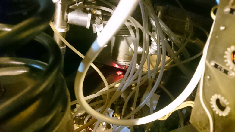
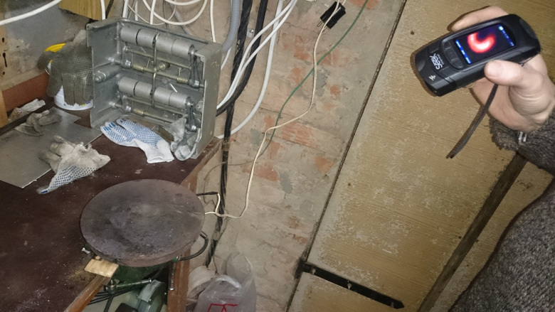
And then I, unsuspecting, decided to make a photo - share it with the other participants of the project, show success!
First of all, I was tense due to the fact that the heater glows red. It was not in my plans, but in controlling the temperature of the pump, everything was in order, 180-190 degrees Celsius. Of course, I immediately de-energized the heater, continuing to cool the diffusor, and continuing to evacuate (the pump warmed up, the oil boils, and continues to pump the vacuum) reached, by inertia, the working pressure of 5 * 10 ^ -5 Torr.
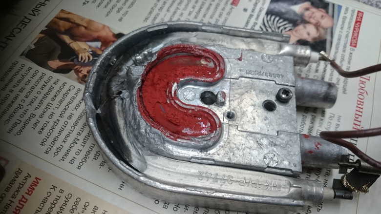
He continued to look at the picture, and noticed a large, beautifully shiny drop on it. It was a drop from that heater, which I milled so cheerfully on the video above ... I
cooled down, I cooled down myself for a few days (from anger, a joke :)), and took it apart again. The heater cannot be restored, everything has melted, including the heating element itself.
But what is the matter, why was there such a bad thermal contact? And the whole thing turned out to be trivial. The stud, with which the heater is attached to the pump, is welded into the housing, and the weld seam protrudes above the surface. Hole, which was already in the heater, I ream the diameter of the studs with a small margin. But the protruding seam provided a gap between the heater and the bottom of the pump. The heater overheated, paste KPT-8 for such gaps (about 1 mm) and temperatures are not intended.
Attempt to pump out number 2. Success
We do not lose heart, we need a new heater. Having read the forums of vacuuming machines on the chip maker and the forum of microscopists, I found out that I am not alone puzzled by the problem of heating the oil in the pump. At first, various original ideas came to my mind. For example, blacken the bottom of the pump and put down a couple of halogen lamps of 500 watts each. Or, put the induction hob so that it warms the bottom of the pump itself. But these methods are either unnecessarily complex (why put a halogen, if you can and you just need to heat), or are not suitable for an electron microscope (an induction cooker will definitely interfere with its radiation to a sensitive device). Therefore, we take the first burner from the electric stove and check whether it works.
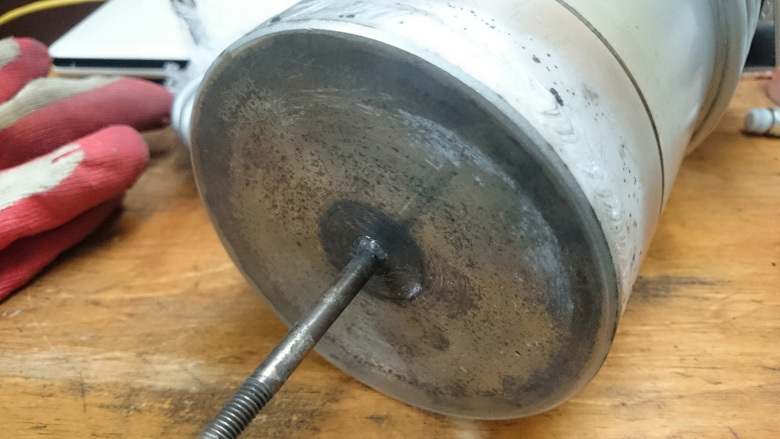
One winding does not work, the second works - and we don’t need it anymore. True, the surface of the burner is rusty on top, not very beautiful, and you don’t want to reheat everything a second time.
We clamp in the lathe, we pierce a surface and we drill an aperture on the center.
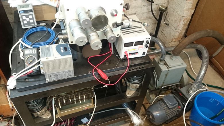
We collect everything to try pumping out. Forvacuum pump, compressor, diaphragm pump for water, a bucket of water as a heat carrier (it is winter in the yard, so there are no problems with cooling), a voltmeter with a vacuum reading in volts. At that time, without any aesthetics, the main thing is functionality. It turned out like this: A
thermometer shows a temperature of 191.1 C, and a voltmeter - 3.33 V. Formulas for converting volts to torr:
For Pirani:

For hot cathode:

Therefore, reading 3.3V corresponds to a vacuum of 4.7 * 10 ^ -5 Torr, which is the working pressure for this microscope. Success! The experiment was repeated ten times, so everything is clear.
To make it more interesting to show the pumping process on video, I did the following: I took a mechanical magneto from an internal combustion engine and started a high voltage output in the lock chamber of a microscope to visually observe how the discharge changes depending on pressure.
Visual vacuum sensors are even built on this effect.
What's next?
Once the vacuum has been reached, and no major problems have been discovered, then you need to do one more boring, but very important thing: arrange everything, organize a rack with the tool, carefully connect and dissolve the wires. In the coming days I’ll take a video of this and post it on my channel . You may have noticed that I published this article with a fairly long break. This is because the articles “caught up” with the progress on the project, and you are now following it in real time.
In the near future, the plan is:
- Installation of the cathode (and at the same time a small alteration of the cathode assembly)
- High-voltage power supply (you need to figure it out, connect it)
- Prototyping circuitry for controlling electromagnetic lenses
- Visualization of the electron beam on the luminescent screen
What do you need?
These articles have produced a good response, thank you for that! And sometimes they ask me what can help in this or related popular science projects. In my plans, there are other experiments with electron optics, thermal and magnetron sputtering.
Just in case, I will share a list of what I would be interested to have for future articles and videos.
- High-voltage power supplies , laboratory, from 0 to 5-10kV, adjustable.
- Signal generators up to 1-2 MHz will be sufficient.
- Высоковакуумная смазка, чтобы промазать уплотнения в микроскопе после очистки. Старая смазка засохла и загрязнена, и только поэтому я ещё не разбирал колонну. С установкой датчика вторичных электронов нужно обязательно всё очистить, иначе сцинтиллятор может быть повреждён.
- Стеклянный колокол или колпак для вакуума (vacuum bell jar). Нигде не могу найти в продаже.
- Маленький диффузионный насосик и сопутствующая вакуумная арматура (клапана).
- Широкодиапазонные датчики вакуума.
- Датчик вторичных электронов, датчик упруго отражённых электронов.
As always, I welcome your comments and thank you for watching!
In the next series - disassemble the electron-optical column.