Raspberry Pi Simulation Expansion Board
For a long time, the Raspberry Pi microcomputer has entered the life of geeks, system administrators, programmers and electronic engineers. Inexpensive and relatively powerful for its class, with built-in I / O ports, it can cope with various tasks and meet user needs. Having bought a Raspberry Pi, I wanted something to turn on, measure, and manage external devices. A large number of expansion cards are currently being sold, such as here, You can use breadboard with wires for rapid prototyping, but I prefer to make devices on my own, for specific tasks. For the first time, I did not use a two-row comb for all outputs, but limited myself to several I / O ports, SPI, I2C and UART bus. I connected the Raspberry Pi with the target wires for prototyping "mom-mom."
In this regard, a series of three prototyping boards was developed, about one of them, the simplest I will discuss in this article.
So what I needed:
According to the above list, an electrical circuit has been developed:
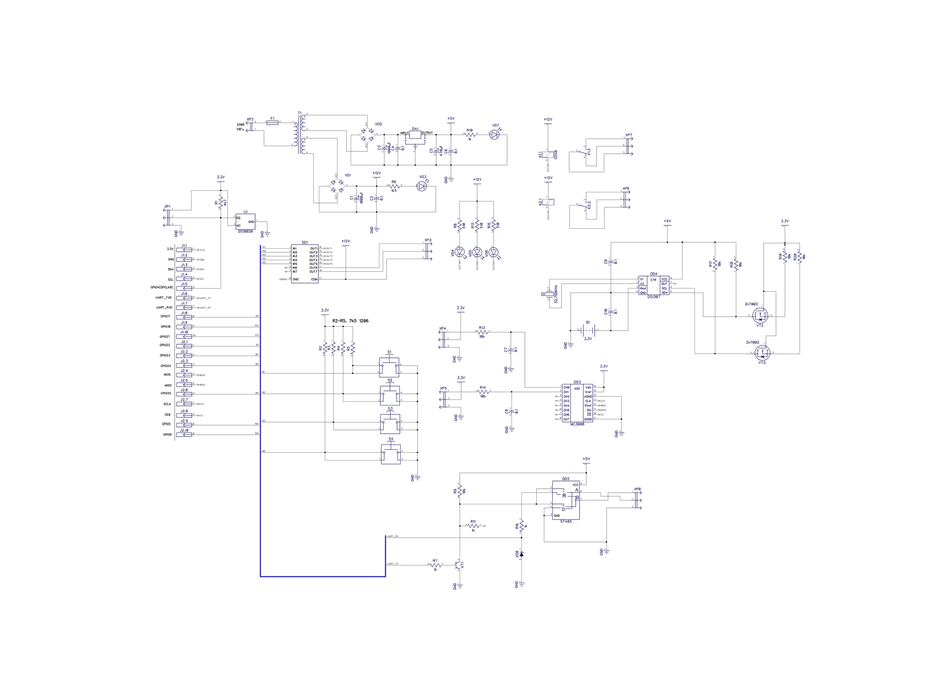
→ A circuit from a high-resolution storage
The circuit uses a transformer power source with two output windings. The first winding operates on a linear voltage regulator with a 5V output, to power the RS485 driver chip and real-time clock. The second winding is used to power electromagnetic relays and assembly with Darlington transistors.
The DS18B20 temperature sensor is powered by + 3.3V from the Raspberry Pi board, the board has a connector for connecting external DS18B20 sensors, the same voltage is taken for the ADC and matching levels with a real-time clock. The circuit uses four buttons S1-S4 to control any actions that operate at a low logic level. To control the loads, the transistor assembly DD1 ULN2003 with built-in protective diodes is used. Relays K1 and K2 are connected to pins 16, 15 of the transistor assembly, LEDs for indication are connected to pins 14-12, pins 11, 10 are designed to connect to external devices according to the scheme with a common collector or additional relays with a winding voltage of + 12V.
To measure voltage, two channels of a 10-bit ADC DD3 MCP3008 with an SPI interface, with an input low-pass filter are used. The analog node is made primitively, for academic purposes or for quick debugging. If the question arises about the qualitative measurement of an analog signal, you will have to decouple the digital and analog ground, use an external voltage reference source. Alternatively, the analog part can be done as follows:

It will only be necessary to use the TTL → LVTTL level converter on the SPI bus.
The real-time clock DD4 is made on the DS1307 chip, and the quartz resonator Q1 at 32.768 kHz is used for clocking. A 3 volt lithium battery soldered into the board is used to power the clock's RAM chip. The microcircuit is connected via a 5V-3.3V level converter made on MOS transistors VT2, VT3 to the Raspberry Pi via the I2C bus (CAD used connection to lines without explicit connection).
As the UART → RS485 driver, the DD2 ST485 chip was used. Circuit solutions using the transistor VT1 allowed to abandon a separate output for controlling the transceiver. It switches to transmit mode only when the UART is transmitting data, the rest of the time ST485 is in receive mode. The transceiver control command is removed from the collector of transistor VT1.
In addition to converting the interfaces, this scheme also performs the function of matching the LVTTL levels of the UART Raspberry Pi interface with the TTL levels of the ST485 driver. The signal taken from the collector of the transistor VT1 pulls the level at the DI input to 5V, and the resistor R16 and the Zener diode VD8 limit the level from the output R0 to 3.3V. Do not pay attention to the resistor R11, it remained in the circuit during debugging. RS485 is tested with ModBus RTU protocol at 115200 baud.
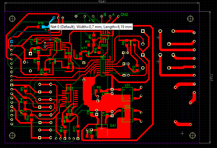
Accordingly, a circuit board was further developed:
Variant of the connection scheme with external devices:

To check the nodes of the expansion board, I used a couple of scripts in python (I don’t know this language, I wrote by trial and error, peering at the codes of specialists)
To measure the voltage from a potentiometer connected to the ADC channels, I wrote a simple script:
The following script was used to work with DS18B20 thermometers:
I also documented the settings in Raspbian:
The circuit board was urgently needed, so I made it myself using LUT technology and a couple of hours of free time. In order to facilitate work and save time, the circuit board was made one-sided with jumpers from MGShV 0.5. DipTrace circuit and PCB design, test source codes, list of components and tutorial with commands for configuration in the
repository .
PS: in the video below, the very first simulation board is used, it was assembled on a breadboard with buttons and LEDs in 20 minutes, the following versions appeared on its basis:
In this regard, a series of three prototyping boards was developed, about one of them, the simplest I will discuss in this article.
So what I needed:
- Work with GPIO with both inputs and outputs;
- Load management;
- Connection of temperature sensors on the 1-Wire bus;
- Voltage measurement;
- Real time clock;
- Monitoring and control of an external device via the RS485 bus;
- Separate power supply for expansion card;
According to the above list, an electrical circuit has been developed:
→ A circuit from a high-resolution storage
The circuit uses a transformer power source with two output windings. The first winding operates on a linear voltage regulator with a 5V output, to power the RS485 driver chip and real-time clock. The second winding is used to power electromagnetic relays and assembly with Darlington transistors.
The DS18B20 temperature sensor is powered by + 3.3V from the Raspberry Pi board, the board has a connector for connecting external DS18B20 sensors, the same voltage is taken for the ADC and matching levels with a real-time clock. The circuit uses four buttons S1-S4 to control any actions that operate at a low logic level. To control the loads, the transistor assembly DD1 ULN2003 with built-in protective diodes is used. Relays K1 and K2 are connected to pins 16, 15 of the transistor assembly, LEDs for indication are connected to pins 14-12, pins 11, 10 are designed to connect to external devices according to the scheme with a common collector or additional relays with a winding voltage of + 12V.
To measure voltage, two channels of a 10-bit ADC DD3 MCP3008 with an SPI interface, with an input low-pass filter are used. The analog node is made primitively, for academic purposes or for quick debugging. If the question arises about the qualitative measurement of an analog signal, you will have to decouple the digital and analog ground, use an external voltage reference source. Alternatively, the analog part can be done as follows:
It will only be necessary to use the TTL → LVTTL level converter on the SPI bus.
The real-time clock DD4 is made on the DS1307 chip, and the quartz resonator Q1 at 32.768 kHz is used for clocking. A 3 volt lithium battery soldered into the board is used to power the clock's RAM chip. The microcircuit is connected via a 5V-3.3V level converter made on MOS transistors VT2, VT3 to the Raspberry Pi via the I2C bus (CAD used connection to lines without explicit connection).
As the UART → RS485 driver, the DD2 ST485 chip was used. Circuit solutions using the transistor VT1 allowed to abandon a separate output for controlling the transceiver. It switches to transmit mode only when the UART is transmitting data, the rest of the time ST485 is in receive mode. The transceiver control command is removed from the collector of transistor VT1.
In addition to converting the interfaces, this scheme also performs the function of matching the LVTTL levels of the UART Raspberry Pi interface with the TTL levels of the ST485 driver. The signal taken from the collector of the transistor VT1 pulls the level at the DI input to 5V, and the resistor R16 and the Zener diode VD8 limit the level from the output R0 to 3.3V. Do not pay attention to the resistor R11, it remained in the circuit during debugging. RS485 is tested with ModBus RTU protocol at 115200 baud.
Accordingly, a circuit board was further developed:
3D models of the printed circuit board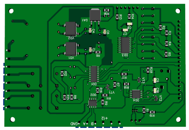
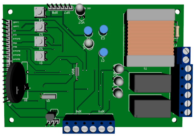
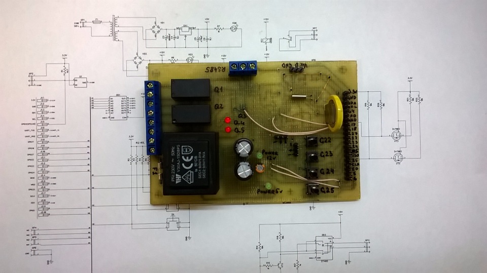
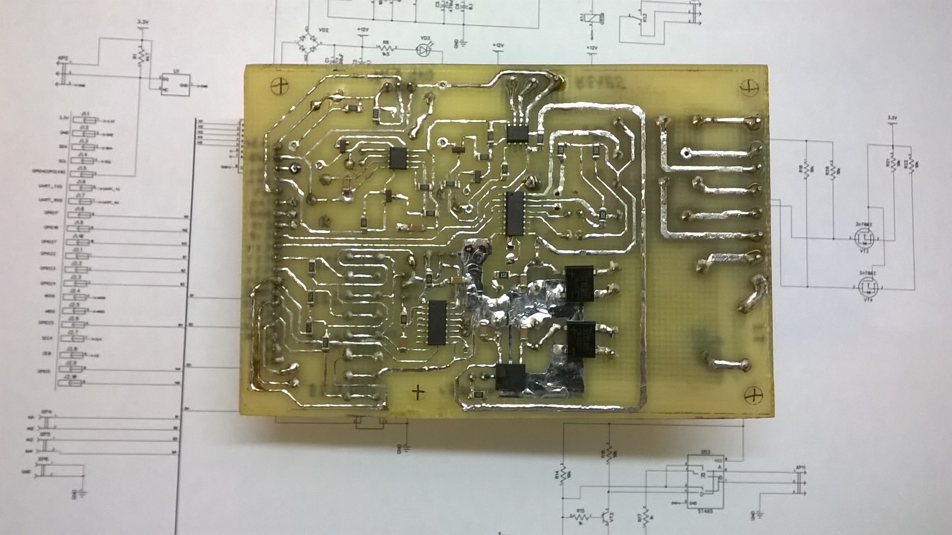
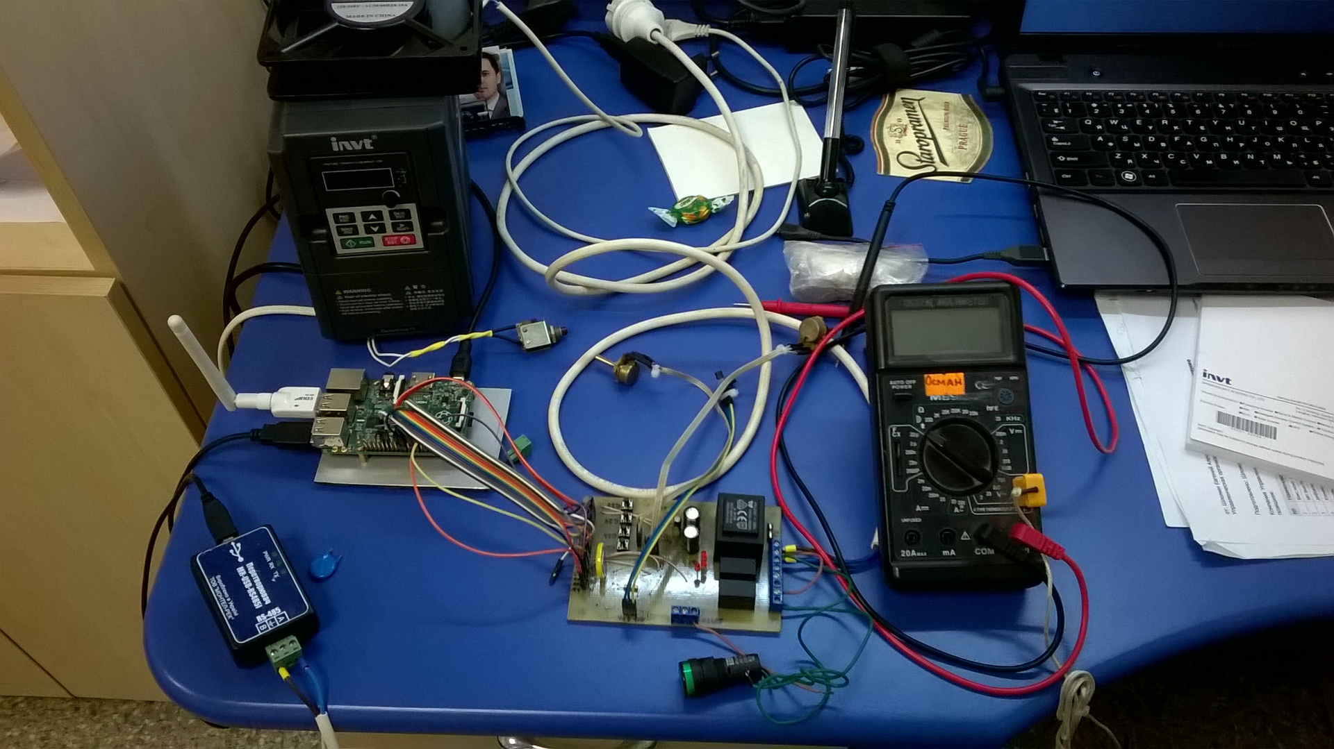
Photo of the finished device and work with the expansion board: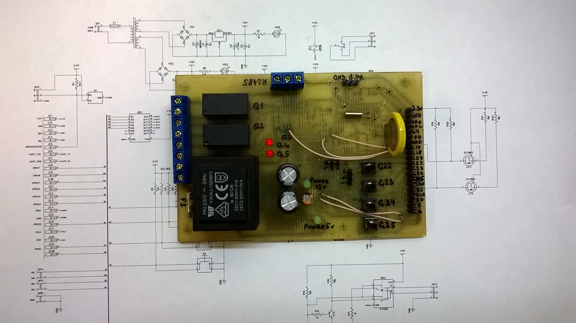
Variant of the connection scheme with external devices:
To check the nodes of the expansion board, I used a couple of scripts in python (I don’t know this language, I wrote by trial and error, peering at the codes of specialists)
To measure the voltage from a potentiometer connected to the ADC channels, I wrote a simple script:
MCP3008 python source
#!/usr/bin/python
# Example program to read data from MCP3008 10 bit ADC
import spidev
import time
import os
# Open SPI bus
spi = spidev.SpiDev()
spi.open(0,0)
# Function to read SPI data from MCP3008 chip
# Channel must be an integer 0-7
def ReadChannel(channel):
  adc = spi.xfer2([1,(8+channel)<<4,0])
  data = ((adc[1]&3) << 8) + adc[2]
  return data
# Function to convert data to voltage level,
# rounded to specified number of decimal places.
def ConvertVolts(data,places):
  volts = (data * 3.3) / float(1023)
  volts = round(volts,places)
  return volts
# Define sensor channels
first_channel = 0
second_channel  = 1
# Define delay between readings
delay = 5
print "------------------------------------------------------"
while True:
  # Read the first channel data
  first_level = ReadChannel(first_channel)
  first_channel_volts = ConvertVolts(first_level,2)
  # Read the second channel data
  second_level = ReadChannel(second_channel)
  second_channel_volts = ConvertVolts(second_level,2)
  # Print out results
  print "------------------------------------------------------"
  print("First ADC channel: {} ({}V)".format(first_level,first_channel_volts))
  print("Second ADC channel : {} ({}V)".format(second_level,second_channel_volts))
  # Wait before repeating loop
  time.sleep(delay)
The following script was used to work with DS18B20 thermometers:
DS18B20 python source
Used code from the site
# Example program to read data from DS18B20
# This code taken from
# https://kropochev.com/?go=all/raspberry-pi-and-onewire-sensor/
import os
import glob
import time
os.system('modprobe w1-gpio')
os.system('modprobe w1-therm')
base_dir = '/sys/bus/w1/devices/'
device_folder = glob.glob(base_dir + '10*')[0]
device_file = device_folder + '/w1_slave'
def read_temp_raw():
    f = open(device_file, 'r')
    lines = f.readlines()
    f.close()
    return lines
def read_temp():
    lines = read_temp_raw()
    while lines[0].strip()[-3:] != 'YES':
        time.sleep(0.2)
        lines = read_temp_raw()
    equals_pos = lines[1].find('t=')
    if equals_pos != -1:
        temp_string = lines[1][equals_pos+2:]
        temp_c = float(temp_string) / 1000.0
        temp_f = temp_c * 9.0 / 5.0 + 32.0
        return temp_c, temp_f
while True:
    print(read_temp())
    time.sleep(1)
I also documented the settings in Raspbian:
Configure devices
- 1 Wire settings:
- Raspbian wheezy
Enter command in console:
pi @ raspberrypi ~ $ sudo modprobe w1-gpio
pi @ raspberrypi ~ $ sudo modprobe w1_therm
Then check sensor in system:
pi @ raspberrypi ~ $ sudo ls / sys / bus / w1 / devices / w1_bus_master1 /
You can see the tabel below entered comman and
there you should find HEX like 28-000002da8328;
This is DS18B20 address;
Next read the data from DS18B20 sensor using command:
pi @ raspberrypi ~ $ cat / sys / bus / w1 / devices / w1_bus_master1 / 28-000002da8328 / w1_sla
And you are going see temperature in console like:
6f 01 4b 46 7f ff 01 10 67: crc = 67 YES
6f 01 4b 46 7f ff 01 10 67 t = 22937
t = 22937 - you should divide this number on 1000 and you will have temperature in Celsius;
- Raspbian Jezzy
Enter command:
pi @ raspberrypi ~ $ sudo nano /boot/config.txt
On next step you should write in config file
dtoverlay = w1-gpio, gpiopin = 4
dtoverlay = w1-gpio-pullup
Then you should reboot your raspberry Pi
- I2C Real Time Clock settings:
- Update your system if it needed and install i2c-tools:
pi @ raspberrypi ~ $ sudo apt-get update
pi @ raspberrypi ~ $ sudo apt-get -y upgrade
pi @ raspberrypi ~ $ sudo apt- get i2c-tools:
Enter command:
pi @ raspberrypi ~ $ sudo nano / etc / modules
Add these lines:
i2c-bcm2708
i2c-dev
rtc_ds1307
Comment one line in file:
pi @ raspberrypi ~ $ sudo nano /etc/modprobe.d/raspi-blacklist.conf
Add # Symbol in beginning of line
blacklist i2c-bcm2708
________________________________________________________
Reboot system;
Enter command:
pi @ raspberrypi ~ $ sudo lsmod
You will see lines like:
rtc_ds1307 7715 0
i2c_dev 5277 0
i2c_bcm2708 4719 0
________________________________________________________
Get DS1307 address:
pi @ raspberrypi ~ $ sudo i2cdetect -y 1
You will see table in console:
0 1 2 3 4 5 6 7 8 9 abcdef
00: - - - - - - - - - - - - - - 10: - - - - - - - - - - - - - - - - -
20: - - - - - - - - - - - - - - - - -
30: - - - - - - - - - - - - UU - - - - -
40: - - - - - - - - - - - - - - - - -
50: - - - - - - - - - - - - - - - - -
60: - - - - - - - - 68 - - - - - - - 70: - - - - - - - -
In address 0x3b some device without driver and 0x68 perhaps DS1307 clock address.
Enter command:
echo ds1307 0x68> / sys / class / i2c-adapter / i2c-1 / new_device
Read clock:
pi @ raspberrypi ~ $ sudo hwclock -r
Set time:
pi @ raspberrypi ~ $ sudo hwclock -w
Set system time from RTC :
pi @ raspberrypi ~ $ sudo hwclock -s
Automatic RTC start;
Add lines in /etc/rc.local file
echo ds1307 0x68> / sys / class / i2c-adapter / i2c-1 / new_device
sudo hwclock -s
Before last line in file looks like:
exit 0
- Uart settings:
- Back up files:
cp /boot/cmdline.txt / boot /cmdline.bak
cp / etc / inittab /etc/inittab.bak
Delete "console = ttyAMA0,115200" and "kgdboc = ttyAMA0,115200" lines from configuration file:
pi @ raspberrypi ~ $ nano /boot/cmdline.txt
Comment last line looks like "T0: 23: respawn: / sbin / getty -L ttyAMA0 115200 vt100: in / etc / inittab file: using # symbol:
pi @ raspberrypi ~ $ nano / etc / inittab
The circuit board was urgently needed, so I made it myself using LUT technology and a couple of hours of free time. In order to facilitate work and save time, the circuit board was made one-sided with jumpers from MGShV 0.5. DipTrace circuit and PCB design, test source codes, list of components and tutorial with commands for configuration in the
repository .
PS: in the video below, the very first simulation board is used, it was assembled on a breadboard with buttons and LEDs in 20 minutes, the following versions appeared on its basis: