DeltaXY mechanics for 3D printer
Bringing the SCARA 3D printer to mind and having achieved sufficient print quality, I began to think about the next craft. This by itself should be a 3d printer.
For myself, I decided that the new printer should meet the following criteria:
- Small (10x10 cm print area) - I already have a large printer and now I want a second one on which it will be possible to print small parts (gears and so on) with a thin nozzle and thin layers
- Fast
- On some kind of non-standard kinematics
Kinematics
I thought for a long time and went through the kinematics that made it possible to print at high speed, simple and compact.
H-bot, corexy are good kinematics, but they require a lot of detail and are relatively complex. Delta is a simple but compact question (and I already had one). Kinematics with a movable table did not suit because of the limitations on compactness. Scara is good but I already have. Articulated arm is also good, but so far it has been put off for the future (by the way, my scara if you turn 90 degrees it will be already half an articulated arm). I thought for a long time, invented experimenting and somehow caught up with delta kinematics, but for 2d cases.
The options for removing one dimension were 2: xy and xz.
XZ - began to prototype, but got the problem - the levers responsible for the perpendicularity of the nozzle to the table did not work out their role well - most likely this is an option, but the manufacturing accuracy should be much better than I did.
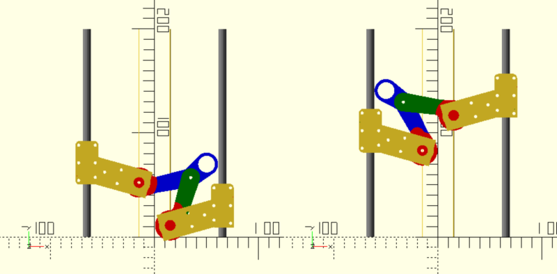
XY - here I was pleased with how it worked and the fact that the number of parts was minimal, also faced the problem of compactness, but moving the centers with a lever closer to the Y axis, it turned out to achieve good compactness - in the classical delta, the final manipulator cannot go beyond the axes of linear movement , a for XY this was not a problem.
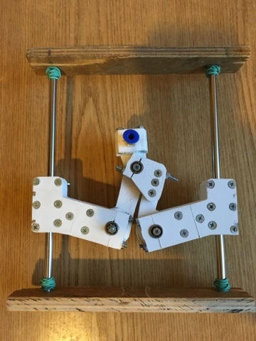
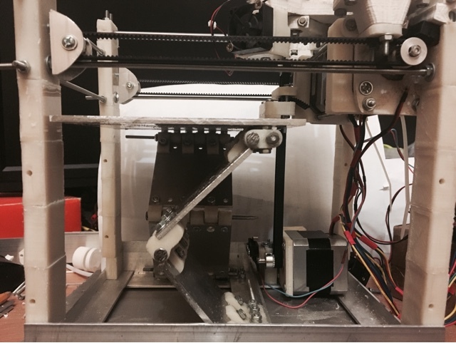
XY axis
The experience suggested to me that the first version is likely to be far from ideal and I decided to do everything as quickly as possible and not really investing in the design, appearance and details, as well as usually also check other ideas that I had. Actually, I built the xy base and designed it in 1 week. She earned and I really liked her result.
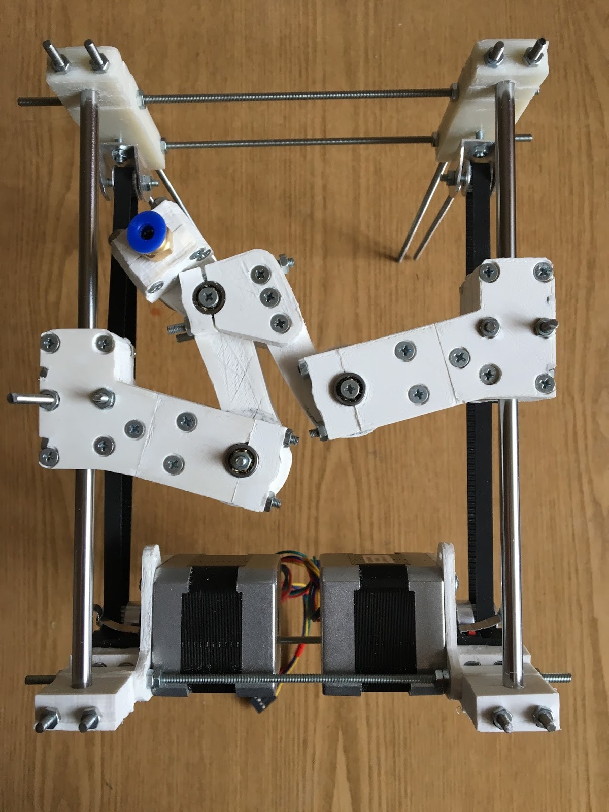
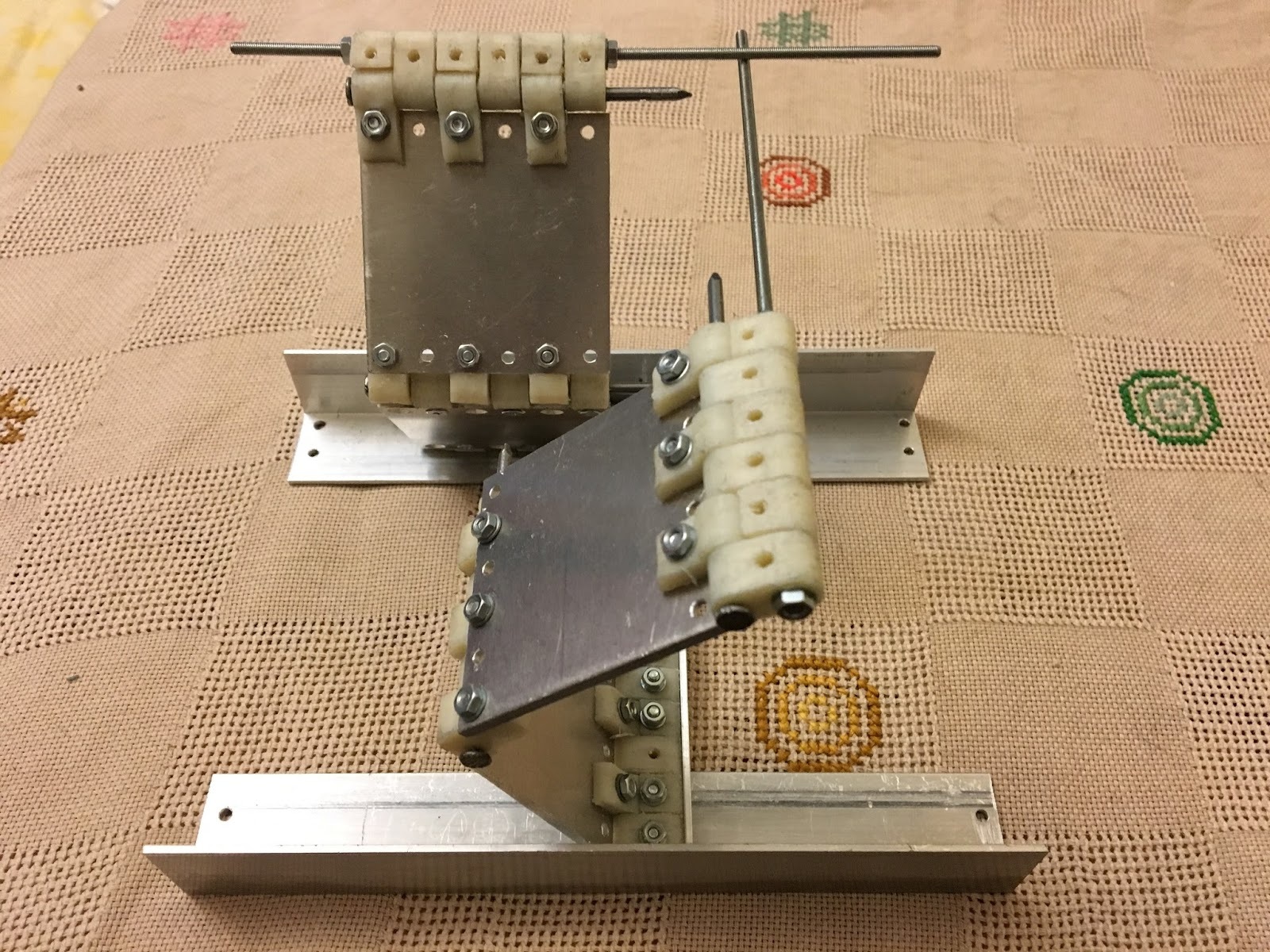
Z axis
Almost 100% working version is two linear guides 4 bearings, a belt or a trapezoidal stud with a nut, it works and is checked by all. But since I decided in advance that I would experiment, I decided to use Sarrus linkage . The first hinges were completely printed out of plastic, but the strength was not particularly different, the second attempt was 3mm aluminum and printing loops - I was satisfied. Another week and the platform was ready.
Heated surface
Actually there is usually nothing to write here, except for the method by which I selected the length and cross section of the nichrome wire.
The essence of the method - instead of using any online calculators (I tried them enough), but you can take a watt Meter and move the wire plus or minus 12v to choose the right length for the required consumption - I was satisfied with 40 watts - it turned out around a meter for 0.4 or 0.5 ( I did not even remember the nichrome wire, if I was not satisfied with the length of the segment, then the same thing was done for a thinner or thicker section. (The table reached 110 degrees as a result of 7 minutes)
Result
Firmware
Online visualizer
OpenScad files
Conclusion
Kinematics test - very satisfied - now I am planning a second version, but already on rails and aluminum (I just fell in love with this material)
The Z axis test - left a double impression, in the second version I will not use it clearly - for a large table 20x20 and with 4 blocks would be better.
For those who read
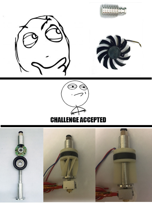
In the process, I checked a prototype of another idea - a hot-end radiator with cooling using an impeller.
One picture instead of a thousand words.