How I made a motion capture suit
Foreword
In my small town I deal with non-trivial technical problems. So this time, the organizers of one show, in which the gymnast was supposed to perform with her program, decided to add some “zest” to her performance. Namely, to display the silhouette of a gymnast who would repeat her movements and somehow interact with other effects, so that everything would be interactive. Solve the problem "in the forehead" failed. Kinect was clearly unable to cope with his task and was not able to capture the movements of a person who is at least 10 meters away from him, also in the dark. So it was decided to do something "his". Looking ahead, I will say that the performance did not take place, but I was so excited about the idea that I continued my experiments as a separate project, which was later calledimpulse .
Beginning of work
I started prototyping the future device as soon as I got the necessary components. Namely:
- Arduino UNO is a well-known designer controller that allows you to develop a prototype in a short time.
- HC-06 - bluetooth module, will serve as a means of wireless communication. The module is very simple, has a UART-interface.
- The MPU-6050 is the only inertial sensor available to me at the time. I got 2 at once to check how they work in pairs, because in the future it is necessary to use up to 15 sensors in one system. This sensor combines an accelerometer and a gyroscope, as well as a temperature sensor to adjust the output data.
After getting everything from this list, I was already eager to see mpu in action. The official Arduino forum was attended by several examples of using these sensors, one of which I used. To connect the sensors, 5 pins (contacts) are used:
- VCC, GND - everything is clear, food and earth. It should be noted that the operating voltage of the sensor is 3.3v, but at 5v it feels good. Power consumption less than 0.05Ah
- SCL, SDA - actually pins, which is "communication" with the sensor. These pins are responsible for the i2c interface. This interface implements switching between devices on one bus, in other words, a bus is a street, and at home there are devices.
- INT - pin for interrupts. As soon as the data on the sensor is ready, the main controller takes it on interruption.
However, this example output only “raw” values from the accelerometer to the terminal, and the code was written to convert to familiar angles, and then the Kalman Filter was implemented, and all of this together took up about 70% of the Arduino UNO resources. Nevertheless, quite smooth values of angles came to the terminal, the device was rather quickly oriented in space, though only a couple of minutes, after which the FIFO buffer was full. But It worked!
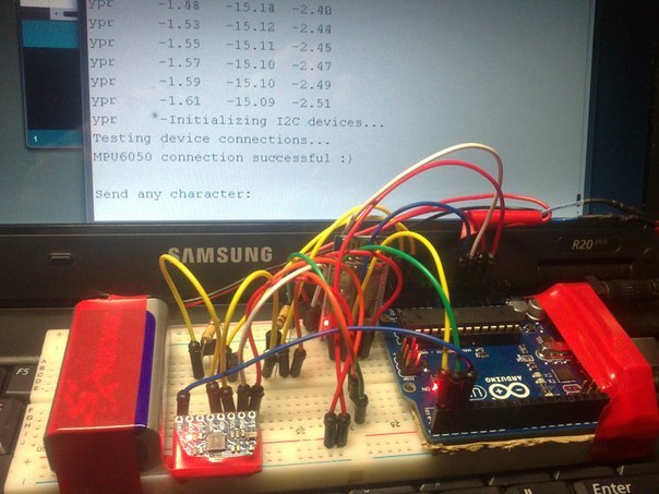
Stabilize!
Gradually, the joy of the working sensor was overshadowed by the duration of the entire system. How much I did not struggle with the FIFO buffer, it overflowed. Here it is worth noting that at that time there was little information about these sensors and similar systems in general, and it had to be collected literally bit by bit. Having decided that the problem lies in the implementation of the i2c interface, I started to google in this direction and found the I2Cdev user library, designed to replace the standard wire library for arduino. A nice surprise was the nested examples of using this library in conjunction with mpu-6050. Having rebuilt the project at this library, I also received raw data and converted them to corners with my code, but there were no overflows anymore. This was a small victory. In the future, studying the insides of the library, I found a lot of useful. For example, Now, data from both sensors and accelerometer and gyroscope are used. The fact is that the accelerometer allows to determine the exact angles of inclination of the device only at rest, while external forces do not act on it, and the gyroscope is designed to compensate for these same forces. The use of data from both sensors became obvious, and here a complementary filter was used. However, there was a problem of zero drift, but more on that later.
More sensors!
And again the underwater stone. This time, the problem that appeared before me was to use the second mpu-6050 sensor. I have already given the analogy of the i2c interface in this article, where the bus is the street and the devices are at home. Imagine that a data packet that must reach a certain device is a postman. The postman needs 2 things - the package and the address, and each house has its own unique address, and the devices must have their own addresses. The problem lies precisely in the address of the mpu-6050 sensor, it is one for all such sensors - 0x68. This address is flashed to the controller of the sensor still at the factory, and it is not possible to find the firmware and change the address for each sensor. Zabugornye forums gave one solution - connecting sensors one after another, one leg of the first sensor connects to pin AD0 of the second,
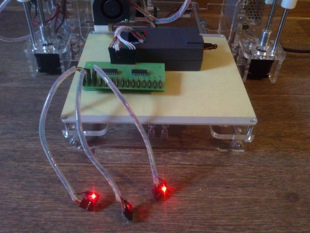
The solution was the transistors. The idea was to put a pair of transistors on pins i2c in front of each sensor and open them one by one. The algorithm is simple - it is necessary to read the data from the 5th sensor, close all the gates except the 5th (or open it if necessary) and read it, then in the same way we obtain data from the others. The result can be seen on the first photo in this article, and it is quite a workable. In a similar way, I managed to connect 4 sensors, this did not have the best effect on stability, and when I ran out of transistors, I decided to use more compact and stable chips.
connection diagram

The only remaining photo from that stage (I apologize for the quality):
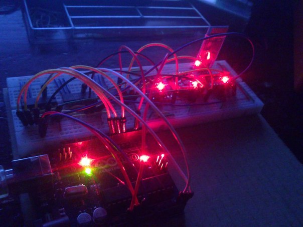
Gate controller
A device that combines these chips and allows you to communicate with a multitude of mpu sensors, I called the gate controller. I was helped to make it by a good friend who already had experience with etching boards, and I needed a quality that my previous attempts at etching did not possess. Because of the multitude of intersecting tracks, a two-layer board was required, but a multilevel one was used as a prototype. The result of this work was such an unusual fee:
piping hot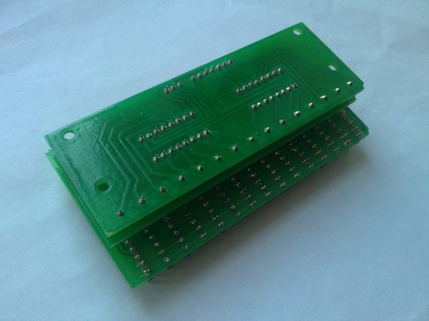
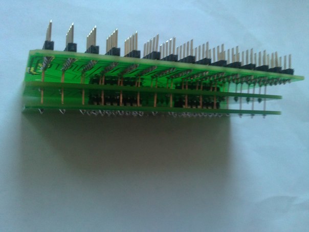
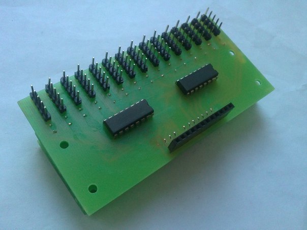


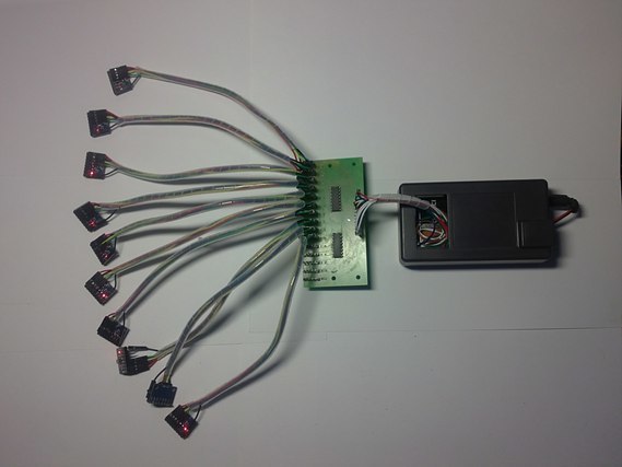
It now remains to check the device in action. Having connected 10 sensors at once, exactly as many pleasant messages about successful initialization appeared in the monitor - the device works!
Gimble lok, quaternions, visualization
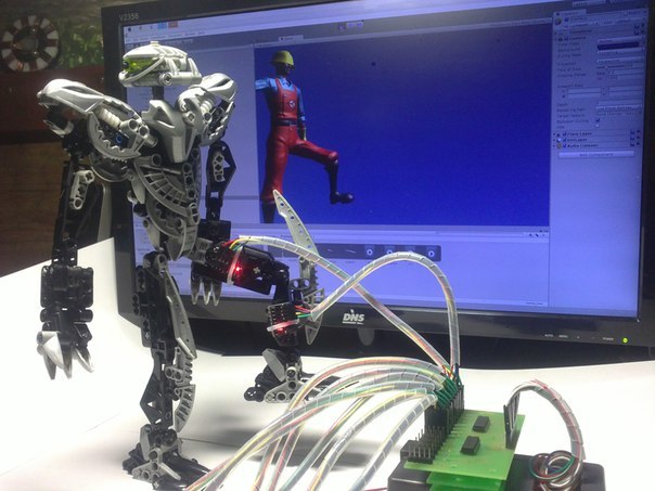
Gimble lok, in Russian a hinged lock or folding frames is an unpleasant phenomenon in the field of gyros and in some cases orientation in space. Without a long explanation of this phenomenon (there are well-explained and illustrative videos on this topic), I would just say that this very hinged lock does not allow the sensor to turn all 360. The XZ axes (deviations from the horizontal plane) are limited from about -45 to 45 degrees, and are not defined correctly beyond these limits. Having studied this topic in more detail, it turned out that the solution is under my nose. The MPU-6050 is a six-axis sensor, and they have dmp on board. Dmp (Digital Motion Processor) deals with everything that I have written for so long in the main code for the main controller firmware, and even filters the values. In addition, dmp can output data in the form of quaternions, what allows to bypass the hinged lock, and also it allows to reduce the size of the sent packages. At this moment, my acquaintance with quaternions continued, previously I worked with them in Unity3D and had some idea. In simple terms, a quaternion is a system of numbers (4 numbers) that describes the rotation of something in space. Just remembering about Unity, I tried to portray something like this:
Controller
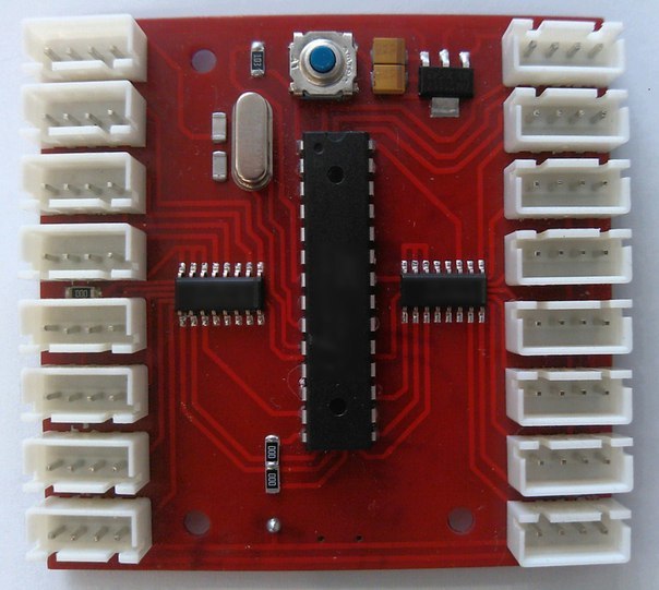
Arduino and the gate controller were completely justified, but their use in the final version was not intended. It's time to make the controller, specific and honed for a specific task. By that time, I pretty much modified the firmware for the future controller, configured the dmp in the optimal way, which made it possible to stop using interrupts. Thus, each sensor was connected on four pins, not five, as before. There was also no need for two of the six chips in the gate controller. All these improvements led to the fact that the board for the future device was designed in two directions, and no “higher level” was required anymore.
Housing
The device gradually acquired its final appearance, and the next step was to make the body logical. The obvious solution is to order or contact 3D printing services. But this is all simple and uninteresting, so for a couple of c friend purchased their own 3D printer. Due to the absence of any instructions, it was collected on an intuitive level, but everything worked out. In general, the assembly, configuration, and the preparation for printing itself deserve a separate article, but now this is not about that. Using all the test material, it remained only to wait until the ABS plastic came.
3D Printer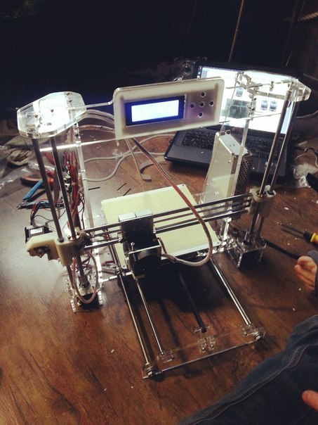


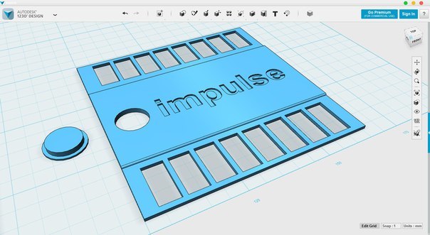
123D-Design was chosen for the simulation. The program is intuitive, and anyone who has at least a little experience in editors of three-dimensional graphics will quickly master it.
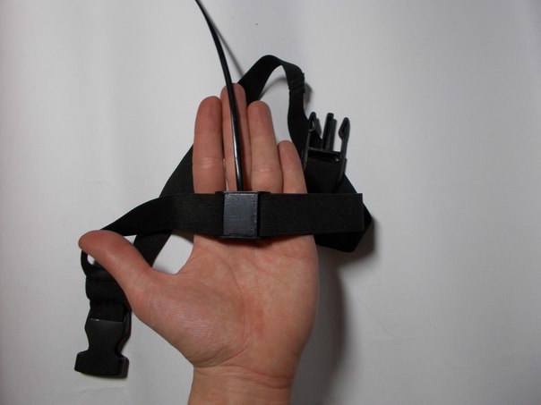
Then I printed all the cases, connected the sensors to the controller through thin 4-pin contact wires, made fixtures for the sensors, put everything together and got a ready-made, autonomous, wearable suit. For the first prototype is quite suitable.
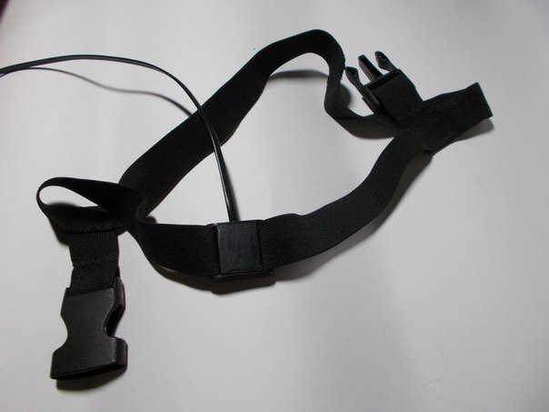

Soft
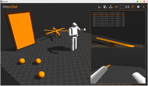
Due to some circumstances, I put Unity3D “for later”, time was running out and it was necessary to quickly write a program for visualization. I have been working with the Xors3D graphics engine for a long time (Maybe someone knows this) and this time it did not let me down. However, after he justified himself, I did not return to Unity, but continued to develop the visual environment for the costume on this engine.
List of current features:
- Visualization - the program displays a model of a person who repeats all movements behind a person in a suit in real time
- Auto-calibration - allows you to instantly calibrate a suit at any time
- Positioning - the model also moves in space as a person can squat, walk, etc.
- Record / Play - all movements can be recorded and played.
- First-person view mode - image output is provided for oculus rift and other virtual reality helmets.
- Interactivity - a person wearing a suit can affect the virtual world. Kicking balls, opening doors, spinning a carousel, etc. (physical engines)
Conclusion
At the moment, the project has 1 fully working, autonomous, wearable and wireless prototype and all the necessary software. It took 8 months to develop this costume (2 of which I rested, totaling 6), but for me this is a whole epoch. During the project, I pumped up my skills, tried and did a lot of things that I had little knowledge of before, and was able to earn some money.
When I started, there was only an interest “and how does it work?” And I did not know about the existence of such suits. However, during the development of at least 3 such projects came to crowdfunding platforms, and I wanted to somehow develop impulse as a commercial project, but it is extremely difficult to declare myself sitting in the Trans-Baikal Territory. Now there is not enough motivation to sit down at the second prototype, already wireless and based on 9 axial sensors, so most likely this project will remain for me just a huge and rewarding experience. In this article I wanted to summarize all the work done, though 20% of it is not displayed here. Not everyone will be interested in tons of code and hours of soldering, 3d-printing, a lot of trial and error, a lot of material spent, but I will try to answer these questions in the comments.
