Using the verifier as a means of rapid modeling of RTL projects. Introduction to UVM
This article will describe the installation and use of free software for modeling digital logic circuits in Verilog as an alternative to commercial products Incisve from Cadense and ModelSim from MentorGraphics. Comparison of simulations in ModelSim and Verilator. A universal verification methodology, UVM, will also be considered.
One of the hardware description languages is verilog. You can write a module in this language.
For example, there is a counter scheme:
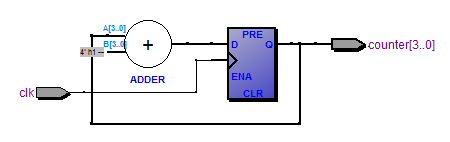
Its code will look like this:
After the simulation, we get the waveforms:
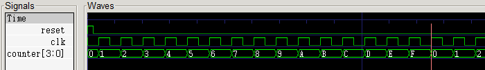
It is clear that the next value, one greater than the previous one, will be written to the counter registers along the clock frequency front.
A written module can have a more complex structure, which will be difficult to manually verify all the states of. We will need automated testing. For this, it is necessary to develop a test environment in one of the programming languages. The test environment will give us the opportunity to conduct a full functional check of the device.
For testing project code, in addition to languages such as Verilog, SystemVerilog, Python (for writing models), you can use the SystemC language. SystemC is a system-level design and verification language for system-level models implemented as an open source C ++ library.
One way to verify Verilog modules using SystemC is to translate verilog files into C ++. Help us with this Verilator.
Verilator is the fastest free Verilog HDL simulator that surpasses most commercial simulators. Verilator compiles synthesized SystemVerilog (usually this is not testbed code), as well as some statements of SystemVerilog and Synthesis into single or multi-threaded C ++ or SystemC code. Verilator was designed for large projects where simulation performance is paramount and is particularly suitable for generating executable processor models for embedded software development teams. Verilator is used to simulate many very large multi-million dollar gateway designs with thousands of modules and is supported by many IP technology providers, including IP from Arm and all of the renowned RISC-V IP providers.
Verilator may not be the best choice if you expect a full-featured replacement for NC-Verilog, VCS or another commercial Verilog simulator, or Verilog behavioral simulator for a very small project. However, if you are looking for a way to port synthesized Verilog to C ++ or SystemC, and your team is free to write only C ++ code, this is a free Verilog compiler for you.
To install the latest version on Ubuntu: download the archive from the link from the official site .
Install:
GTKWave is a full-featured waveform viewer and also allows you to convert files from vcd to fst format, more convenient and faster.
Install:
A language for designing and verifying system-level models implemented in the form of an open source C ++ library.
As mentioned earlier, verilator supports systemc, so you need to create a project in which the test benchmark will be described on systemc, and the source files on synthesized verilog. To do this, we need the g ++ compiler libraries provided by Accelera. Accellera Systems Initiative is an independent, nonprofit organization dedicated to creating, supporting, promoting, and promoting system level design, simulation, and verification standards for use in the global electronics industry.
Download the archive:
http://accellera.org/images/downloads/standards/systemc/systemc-2.3.1a.tar.gz
Install:
This article will review a project that implements UVM verification tools. Verification is a confirmation of the conformity of the final product with predefined reference requirements. One of their verification tools can be tests. In order to run test sequences on models of real devices at the level of RTL descriptions, it is necessary to develop a test environment.
UVM - (Universal Verification Methodology) is a universal verification methodology, a standard that enables the efficient development and reuse of IP block validation environments. UVM is a verification methodology whose tasks include organizing an effective environment around the unit under test. Its advantages:
UVM methodologies consist of two parts: a set of rules for building a test environment and a library of block blanks for verification, for example, a text generator, statistics collector, etc. The main advantage of UVM is its versatility and compatibility with third-party environments.
Since systemc supports the UVM methodology, let's move on to installing the necessary libraries.
Download the archive:
https://www.accellera.org/images/downloads/drafts-review/uvm-systemc-1.0-beta2.tar.gz
Install:
We create an alliance:
Copy the contents of the / usr / local / uvm_systemc_aliance / and /usr/local/systemc-2.3.1/ folders to this folder.
Download the finished project from the link:
https://github.com/paprikun/SYSTEMC/
Open the verilator examples folder.
The rtl folder contains a description of the device. In this example, it is a PWM controller.
In the sim folder makefile file for building the project.
In the tb folder is the code for the verifier. The tb / uvm folder contains an example of uvm environment. The main file is an entry point in testing; it connects the device under test with the uvm environment.
We try to build the project from the sim folder with the make all command. We see an error:
We fix it by replacing line 120:
Once again, we try to run the testbench and stumble upon warning:
Change auto_ptr to unique_ptr.
Now that the libraries are installed and working, we are building the project: make all. The simu executable file should appear in the sim folder. This is an object created by the compiler. We start it with the ./simu team. The following should appear:
When the simulation finishes, the wafeform recording ends. The simu.vcd file can be opened with the gtkwave program:

To display the signals on the left, select SystemC, then, holding Shift, select any signals, and click Append. Tooltips appear on the toolbar when you hover. The mouse scroll works, you need to hold shift or cntrl.
There are also ways to convert this file to another smaller one.
If there are modelsim will do the conversion. In the terminal, enter the vsim command. In the terminal modelsim:
Or using gtkwave in linux terminal:
To compare the simulation time, a similar project was created, but already for Modelsim . Folder modelsim_example. Similarly created UVM environment. The syntax is similar despite the fact that different languages. If you installed Modelsim with uvm support, you can run the make all command.
In addition to the environment in both projects, real-time simulation of measurements was taken.
In time, the difference turned out:
As you can see from the table, verilator has an advantage. The data are presented for a PC with 8GB of RAM, an 8-core processor, 800 MHz, loading one core.
Compare the file size:
Here verilator loses, but you can experiment with creating waveforms and trace depth, the recording period (the beginning and end of waveform recording can be shifted). Which file to work with is up to you.
During testing, in addition to the time of the simulation itself, a discrepancy was found in the reading of input data from the in bus. If the data from the in bus changes during the clk front, Modelsim read the data after the front, verilator before:
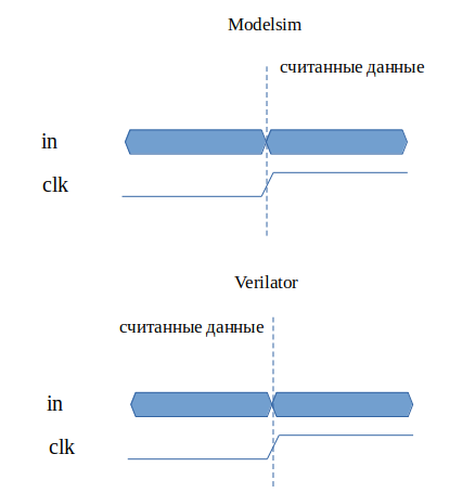
During testing, this point needs to be taken into account, since part of the test environment for different simulators will work differently.
Also, the verilator does not take into account the "x" state of the signal and translates everything to "0";
Consider the test environment, the tb / uvm folder.
UVM testbench is the environment above the device. In this example, the device is a PWM controller. UVM environment diagram:
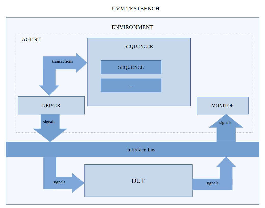
As you can see in the UVM diagram, it consists of blocks (classes). Each block performs its functions. The example shows one of the possible layouts of the test environment. The name and functionality of each class corresponds to the class from which it is inherited. Let's consider each class in more detail.
Environment- file env.h or env.svh. This is a class that can contain one or more agent classes, in which three classes are connected: sequencer, driver, monitor. There is no agent in the example, but its function is implemented in the env class. For the test we need to write some sequence of actions - sequencing.
Let's move on to the sequencing start code:
Sequencer (sequencer) - file sequncer.h. In system verilog, it turned out to use the default sequencer. A class that contains one or more sequences (sequence) (files sequence_a.h, sequence_a.svh). Each sequence is a chain of actions. One of these actions may be sending a transaction. Transaction - transferring data from one class to another. The class in which the transactions are described is bus_trans. Below is a description of two classes, each of which ideologically has its own specific functions: driver and monitor.
Driver - file drv.h, drv.svh. A class that receives transactions from a sequencer and translates them into signals. The driver serves as a sequencer assistant at a lower level. Consider sending one package.
Sequence opens a transaction window, the driver detects this event and starts receiving data. The sequence is waiting for a response from the driver. The driver simulates the signals for the device, then signals the sequencer that the window can be closed. The idea is that the sequencer works at a high level, and the driver at a lower level.
Signals are connected via the interface bus to the device. The interface is described in the files vip_if.h, vip_if.svh.
Next, you need to check whether the output signals match the expected ones. There are two solutions:
In the example, the second option is considered. To test the device at the functional level, it is necessary to compare the output with the expected. The requirement for the device was the correctness of the given duty cycle of the signal and the period of the signal. To monitor the output signals, a new class is written - Monitor (file monitor.h, monitor.svh). Usually, in a test environment, the monitor transfers the signals in the transaction (to a higher level) and is sent to the comparison class - scoreboard.
In this example, the signals are checked immediately. In case of discrepancy between the expected value and the measured, the test stops.
SystemC UVM Software Installation
1. The verilator
One of the hardware description languages is verilog. You can write a module in this language.
For example, there is a counter scheme:
Its code will look like this:
reg [3:0]counter;
always @(posedge clk or posedge reset)
  if(reset)
    counter <= 4'd0;
  else
    counter <= counter + 1'd1;
After the simulation, we get the waveforms:
It is clear that the next value, one greater than the previous one, will be written to the counter registers along the clock frequency front.
A written module can have a more complex structure, which will be difficult to manually verify all the states of. We will need automated testing. For this, it is necessary to develop a test environment in one of the programming languages. The test environment will give us the opportunity to conduct a full functional check of the device.
For testing project code, in addition to languages such as Verilog, SystemVerilog, Python (for writing models), you can use the SystemC language. SystemC is a system-level design and verification language for system-level models implemented as an open source C ++ library.
One way to verify Verilog modules using SystemC is to translate verilog files into C ++. Help us with this Verilator.
Verilator is the fastest free Verilog HDL simulator that surpasses most commercial simulators. Verilator compiles synthesized SystemVerilog (usually this is not testbed code), as well as some statements of SystemVerilog and Synthesis into single or multi-threaded C ++ or SystemC code. Verilator was designed for large projects where simulation performance is paramount and is particularly suitable for generating executable processor models for embedded software development teams. Verilator is used to simulate many very large multi-million dollar gateway designs with thousands of modules and is supported by many IP technology providers, including IP from Arm and all of the renowned RISC-V IP providers.
Verilator may not be the best choice if you expect a full-featured replacement for NC-Verilog, VCS or another commercial Verilog simulator, or Verilog behavioral simulator for a very small project. However, if you are looking for a way to port synthesized Verilog to C ++ or SystemC, and your team is free to write only C ++ code, this is a free Verilog compiler for you.
To install the latest version on Ubuntu: download the archive from the link from the official site .
Install:
#sudo apt-get install make autoconf g++ flex bison   # Prerequisites
unsetenv VERILATOR_ROOT  # For csh; ignore error if on bash
unset VERILATOR_ROOT  # For bash
tar xvzf verilator*.t*gz
cd verilator*
./configure
make
sudo make install
2. GTK Wave
GTKWave is a full-featured waveform viewer and also allows you to convert files from vcd to fst format, more convenient and faster.
Install:
sudo apt-get install gtkwave3. SYSTEMC
A language for designing and verifying system-level models implemented in the form of an open source C ++ library.
As mentioned earlier, verilator supports systemc, so you need to create a project in which the test benchmark will be described on systemc, and the source files on synthesized verilog. To do this, we need the g ++ compiler libraries provided by Accelera. Accellera Systems Initiative is an independent, nonprofit organization dedicated to creating, supporting, promoting, and promoting system level design, simulation, and verification standards for use in the global electronics industry.
Download the archive:
http://accellera.org/images/downloads/standards/systemc/systemc-2.3.1a.tar.gz
Install:
tar -xvf systemc-2.3.1a.tar.gz
cd systemc-2.3.1a
mkdir objdir
sudo ./configure --prefix=/usr/local/systemc-2.3.1a/
sudo make
sudo make install
cd ../
4. UVM for SYSTEMC
This article will review a project that implements UVM verification tools. Verification is a confirmation of the conformity of the final product with predefined reference requirements. One of their verification tools can be tests. In order to run test sequences on models of real devices at the level of RTL descriptions, it is necessary to develop a test environment.
UVM - (Universal Verification Methodology) is a universal verification methodology, a standard that enables the efficient development and reuse of IP block validation environments. UVM is a verification methodology whose tasks include organizing an effective environment around the unit under test. Its advantages:
- clear structure in the form of dedicated blocks deciding specific
- tasks;
- the ability to reuse blocks in subsequent projects;
- the maximum possible automation of verification;
- the most complete reporting information allowing, when an error occurs, to identify its causes as quickly and accurately as possible and suggest solutions.
UVM methodologies consist of two parts: a set of rules for building a test environment and a library of block blanks for verification, for example, a text generator, statistics collector, etc. The main advantage of UVM is its versatility and compatibility with third-party environments.
Since systemc supports the UVM methodology, let's move on to installing the necessary libraries.
Download the archive:
https://www.accellera.org/images/downloads/drafts-review/uvm-systemc-1.0-beta2.tar.gz
Install:
tar -xvf uvm-systemc-1.0-beta2.tar.gz
cd  uvm-systemc-1.0-beta2/
mkdir objdir
sudo ./configure --prefix=/usr/local/systemc_uvm/ --with-systemc=/usr/local/systemc-2.3.1a
sudo make
sudo make install
We create an alliance:
sudo mkdir /usr/local/uvm_systemc_alianceCopy the contents of the / usr / local / uvm_systemc_aliance / and /usr/local/systemc-2.3.1/ folders to this folder.
Download the finished project from the link:
https://github.com/paprikun/SYSTEMC/
Open the verilator examples folder.
The rtl folder contains a description of the device. In this example, it is a PWM controller.
In the sim folder makefile file for building the project.
In the tb folder is the code for the verifier. The tb / uvm folder contains an example of uvm environment. The main file is an entry point in testing; it connects the device under test with the uvm environment.
We try to build the project from the sim folder with the make all command. We see an error:
/usr/local/uvm_systemc_aliance//include/systemc.h:120:16: error: ‘std::gets’ has not been declared
using std::gets;
We fix it by replacing line 120:
#if defined(__cplusplus) && (__cplusplus < 201103L)
using std::gets;
#endif
Once again, we try to run the testbench and stumble upon warning:
/usr/local/uvm_systemc_aliance//include/sysc/packages/boost/get_pointer.hpp:21:40: warning: ‘template class std::auto_ptr’ is deprecated [-Wdeprecated-declarations]
template T * get_pointer(std::auto_ptr const& p)
Change auto_ptr to unique_ptr.
Project assembly and simulation
Now that the libraries are installed and working, we are building the project: make all. The simu executable file should appear in the sim folder. This is an object created by the compiler. We start it with the ./simu team. The following should appear:
        SystemC 2.3.1-Accellera --- Jun 28 2019 11:39:29
        Copyright (c) 1996-2014 by all Contributors,
        ALL RIGHTS RESERVED
   Universal Verification Methodology for SystemC (UVM-SystemC)
              Version: 1.0-beta2  Date: 2018-10-24
          Copyright (c) 2006 - 2018 by all Contributors
            See NOTICE file for all Contributors
                    ALL RIGHTS RESERVED
         Licensed under the Apache License, Version 2.0
UVM_INFO @ 0 s: reporter [RNTST] Running test ...
simulation real time = 9 sec
UVM_INFO uvm_default_report_server.cpp(666) @ 179490249010 ps: reporter [UVM/REPORT/SERVER]
--- UVM Report Summary ---
** Report counts by severity
UVM_INFO      :   1
UVM_WARNING   :   0
UVM_ERROR     :   0
UVM_FATAL     :   0
** Report counts by id
[RNTST]                 1
UVM_INFO @ 179490249010 ps: reporter [FINISH] UVM-SystemC phasing completed; simulation finished
When the simulation finishes, the wafeform recording ends. The simu.vcd file can be opened with the gtkwave program:
To display the signals on the left, select SystemC, then, holding Shift, select any signals, and click Append. Tooltips appear on the toolbar when you hover. The mouse scroll works, you need to hold shift or cntrl.
There are also ways to convert this file to another smaller one.
If there are modelsim will do the conversion. In the terminal, enter the vsim command. In the terminal modelsim:
vcd2wlf simu.vcd simu.wlfOr using gtkwave in linux terminal:
vcd2lxt   simu.vcd simu.lxt
vcd2lxt2  simu.vcd simu.lxt2
To compare the simulation time, a similar project was created, but already for Modelsim . Folder modelsim_example. Similarly created UVM environment. The syntax is similar despite the fact that different languages. If you installed Modelsim with uvm support, you can run the make all command.
In addition to the environment in both projects, real-time simulation of measurements was taken.
In time, the difference turned out:
| Wednesday | wafeform | command to run | simulation time (sec.) |
| Modelsim | Yes | make sim TRACE = 1 | 18 |
| Verilator | Yes | make sim TRACE = 1 | 9 |
| Modelsim | нет | make sim TRACE = 0 | 10 |
| Verilator | нет | make sim TRACE = 0 | 4 |
As you can see from the table, verilator has an advantage. The data are presented for a PC with 8GB of RAM, an 8-core processor, 800 MHz, loading one core.
Compare the file size:
| simu.vcd | 807.7 MB |
| simu.wlf (conversion created in Verilator) | 41 MB |
| simu.wlf (created in modelsim) | 9.3 MB |
| simu.lxt | 128 MB |
| simu.lxt2 | 162 MB |
Here verilator loses, but you can experiment with creating waveforms and trace depth, the recording period (the beginning and end of waveform recording can be shifted). Which file to work with is up to you.
During testing, in addition to the time of the simulation itself, a discrepancy was found in the reading of input data from the in bus. If the data from the in bus changes during the clk front, Modelsim read the data after the front, verilator before:
input clk;
input [7:0] in;
reg [7:0] in_last_ ;
...
always @(posedge clk)
begin
...
 in_last_ <= in;
...
end
During testing, this point needs to be taken into account, since part of the test environment for different simulators will work differently.
Also, the verilator does not take into account the "x" state of the signal and translates everything to "0";
UVM TESTBENCH
Consider the test environment, the tb / uvm folder.
UVM testbench is the environment above the device. In this example, the device is a PWM controller. UVM environment diagram:
As you can see in the UVM diagram, it consists of blocks (classes). Each block performs its functions. The example shows one of the possible layouts of the test environment. The name and functionality of each class corresponds to the class from which it is inherited. Let's consider each class in more detail.
Environment- file env.h or env.svh. This is a class that can contain one or more agent classes, in which three classes are connected: sequencer, driver, monitor. There is no agent in the example, but its function is implemented in the env class. For the test we need to write some sequence of actions - sequencing.
Let's move on to the sequencing start code:
sequence_[n]->start(sqr, NULL);Sequencer (sequencer) - file sequncer.h. In system verilog, it turned out to use the default sequencer. A class that contains one or more sequences (sequence) (files sequence_a.h, sequence_a.svh). Each sequence is a chain of actions. One of these actions may be sending a transaction. Transaction - transferring data from one class to another. The class in which the transactions are described is bus_trans. Below is a description of two classes, each of which ideologically has its own specific functions: driver and monitor.
Driver - file drv.h, drv.svh. A class that receives transactions from a sequencer and translates them into signals. The driver serves as a sequencer assistant at a lower level. Consider sending one package.
Sequence opens a transaction window, the driver detects this event and starts receiving data. The sequence is waiting for a response from the driver. The driver simulates the signals for the device, then signals the sequencer that the window can be closed. The idea is that the sequencer works at a high level, and the driver at a lower level.
Signals are connected via the interface bus to the device. The interface is described in the files vip_if.h, vip_if.svh.
Next, you need to check whether the output signals match the expected ones. There are two solutions:
- Writing a model for a device
- Signal Verification through UVM Agent
In the example, the second option is considered. To test the device at the functional level, it is necessary to compare the output with the expected. The requirement for the device was the correctness of the given duty cycle of the signal and the period of the signal. To monitor the output signals, a new class is written - Monitor (file monitor.h, monitor.svh). Usually, in a test environment, the monitor transfers the signals in the transaction (to a higher level) and is sent to the comparison class - scoreboard.
In this example, the signals are checked immediately. In case of discrepancy between the expected value and the measured, the test stops.