Wireless object communication module WISE-4000

Can I deploy an industrial-level data collection system without programming skills? In this article we will get acquainted with devices that allow you to get a ready-made digital signal processing system available through the JSON API in a few clicks.
The WISE-4000 series are I / O devices for logging, monitoring and transmitting data from remote sites. They support industry protocols MQTT, Modbus / TCP and have HTTP JSON API. There is integration with cloud services Microsoft Azure, Dropbox and others.
Devices can work both as part of SCADA and autonomously. Supported network connection via WiFi.
Specifications
- Digital and outputs (DI / DO) - Available with 8 and 4 digital inputs and 4 digital outputs.
- Power Relays - The WISE-4060 model has a 4-channel relay on board that allows you to control the power load.
- Industrial Protocol Support - Digital Channel Management and Data Acquisition via Modbus / TCP and MQTT
- Support for cloud providers - upload data to Microsoft Azure, Dropbox, Alibaba Cloud
- WiFi support - support for 802.11b / g / n protocols, work in station (client) and access point (AP) mode.
- Web-based interface - all configuration can be done via the web-based interface, without using third-party programs
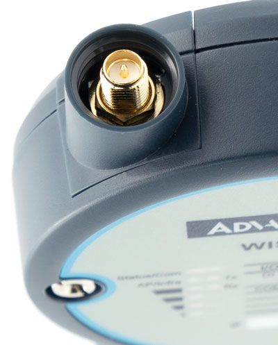
- SMA connector for antennas - the ability to connect third-party antennas instead of the standard one.
- Real-time clock - Self-powered RTC module to maintain accurate time in the event of a power outage and loss of communication.
- 10-30VDC operation - with protection against improper power connection
Initial setup
 Initial configuration takes place via the web interface: the device is transferred to the access point mode with the network name (SSID) of the form WISE- <model <-
It is important to keep in mind that switching to setup mode does not reset the web interface password to the factory one. In order to reset the settings, you must use the utility under Windows Adam / Apax. Utility net .
In the web interface, you can set the Wi-Fi client mode (Infrastrucutre mode) or access point mode (AP Mode).

In client mode, you can set two different Wi-Fi networks to which the device will try to connect. As a second network, it is convenient to use the service network for configuration, to which the device will automatically connect when it is at the service stand. After setting up the network, you can set the DIP switch SW1-P1 to ON.
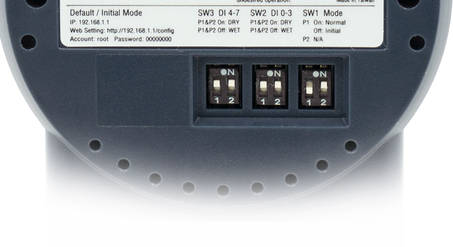
DIP switches on the back cover WISE-4051
Input / output ports
Let us examine the assignment of input / output ports using the example of the WISE-4051 model , which has eight digital input (DI) ports and one RS-485 port for Modbus / RTU Master. The main purpose of this model is to collect data from sensors and monitor remote objects.
Logical Levels
Ports 0-3 are of dry contact type. A logical unit is a closed contact with DCOM0, and a logical zero, respectively, is an open open contact. Reed switches, relays, buttons can be connected to this contact.
Ports 4-7 are of wet contact type. The logical unit is considered to be 10-30V, and the logical zero is 0-3V between the contact and ground DCOM1.
All ports support inversion of logic levels, as well as a pulse signal with a frequency of up to 3 kHz.
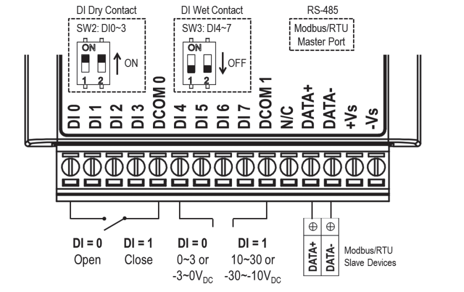
Port Assignment WISE-4051
I / O Modes
Each of the digital inputs can independently operate in one of five input signal processing modes. Depending on the selected mode, the received signal will be stored in different ways in the device memory. Each of the modes allows you to invert the logical zero and one.

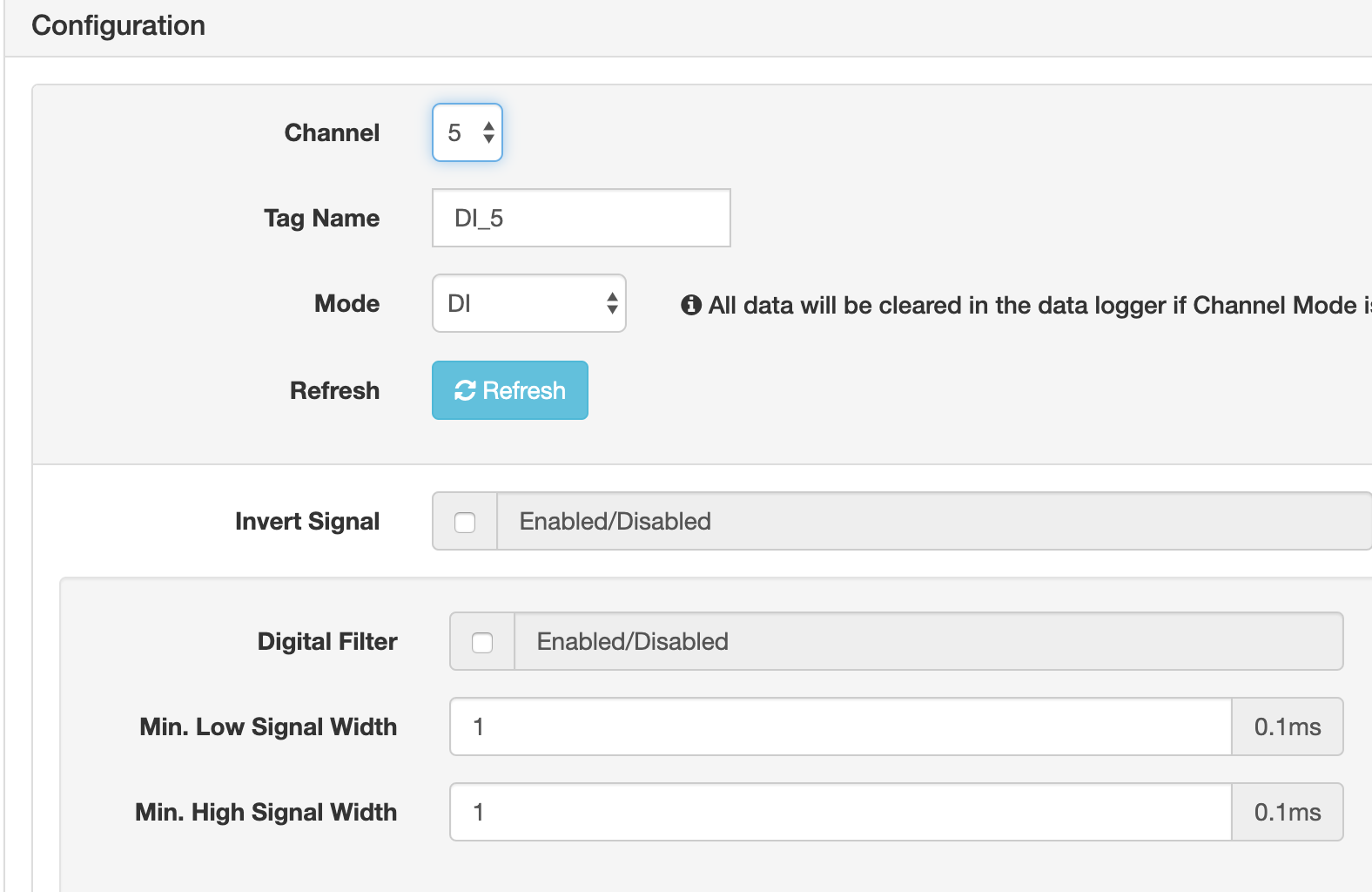
DI - conventional digital input
This mode allows you to read the status of the contact Low / High. Additionally, you can activate the interference filter by setting the minimum and maximum signal lengths in tenths of a millisecond.
Counter
The counter mode sequentially counts the number of received signals and saves their number. Additionally, you can set the starting value of the variable. This mode is convenient to use for counting regular events, for example, the operation of a reed switch to assess the patency of different doors.

Digital Input Counter Mode
Alarm Mode (Latch)
In this mode, a single signal irrevocably switches the input state to the operation mode until it is forcibly reset by API or manually. This mode is useful for alarms, fuses, and any signals that require personnel intervention.
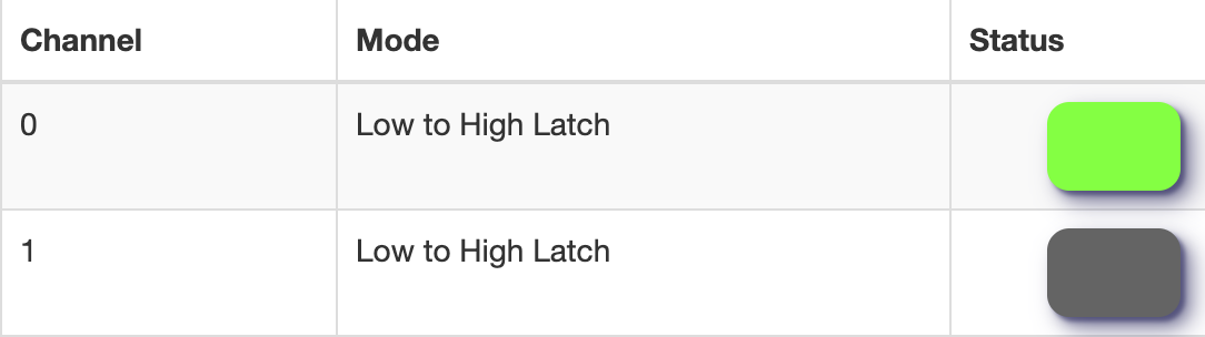
Two digital contacts in alarm mode. Pin 0 is in alarm state.
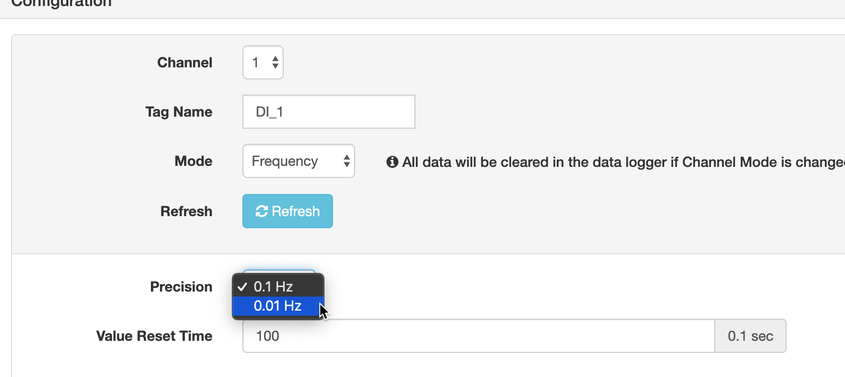
Frequency Measurement Mode
It stores the current value of the signal frequency with an accuracy of 0.1 to 0.01 Hz. Additionally, you can set the time interval for zeroing the value. This mode can be used for pulse signals, rev counter, motors, oscillations, etc.
Local storage
The device can save the received signals to internal memory in case of loss of connection with the server or for fully autonomous operation. The backup battery allows you to store data in volatile memory when the main power is turned off.
Requests for local storage can be done through the web interface, Modbus / TCP, and the HTTP RESTful API.

Local storage request via web interface.
HTTP RESTful
For an example of working with the HTTP API, let's try to deploy a simple test bench. To the input No. 3, we will connect the usual mechanical button and set the counter mode in the web interface. Press the button several times to check if the value is changing.
The web interface shows that the counter value is increasing.

The value of the input counter No. 3 in the web interface
Next, we will try to read the status of the counter using the HTTP API described in the documentation . To do this, we perform a GET request using the curl utility, where 10.0.0.1 is the device ip address, di_value means Digital Input Value, slot_0 is the slot number and ch_3- port number on the device. Since HTTP Basic Auth is used, the username and password can be passed to the URL.
curl http://username:password@10.0.0.1/di_value/slot_0/ch_3
{
  "Ch": 3,
  "Md": 1,
  "Val": 27,
  "Stat": 0,
  "Cnting": 1,
  "OvLch": 0
}
We analyze the values in the answer:
Ch is the input number, in our case, No. 3.
Md is the operating mode, in our case the “counter” (0 - DI, 1 - Counter, 2 - LowToHighLatch, 3 - HighToLowLatch, 4 - Frequency).
Val - value of the counter, in our case - the number of button presses.
Thus, without programming skills and installing additional software, using only the web interface, in five minutes we were able to set up a simple data collection and storage device that can be easily integrated into any modern system. Despite the fact that this example is quite primitive, it gives a general understanding of the ease of configuration. By the same principle, more complex systems can be deployed with heterogeneous data types and operating modes.
Cloud providers
WISE-4000 Series devices support integration with cloud services. The collected data can be transferred to the cloud storage via the MQTT protocol or uploaded as files to the dropbox or to the internal server. It also supports integration with the Advantech WebAccess SCADA system
Microsoft azure
 To connect the device to the Microsoft Azure IoT Hub, just specify the server address, device name and secret token.
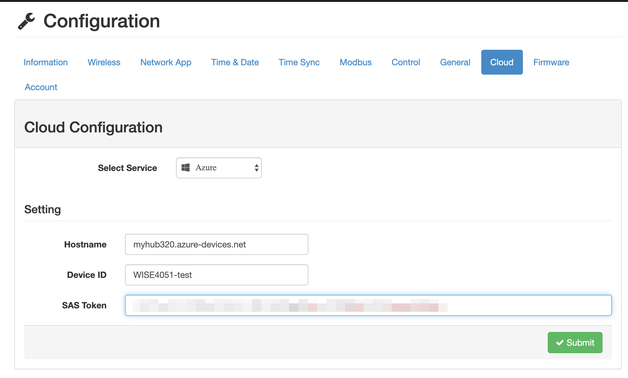
Dropbox
 To connect Dropbox, Oauth2 authorization is used, right in the web interface. Data from local storage will be downloaded as * .csv files. This feature can be used to back up or process data manually.
SDK for developers
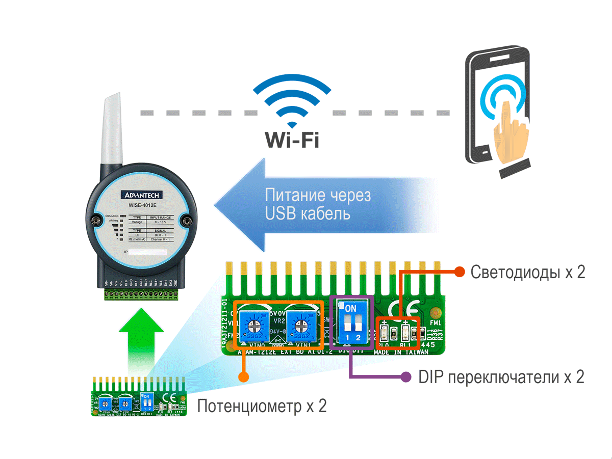
The WISE-4012E kit is specifically designed for convenient development and debugging of WISE-4000 based systems . The kit includes a WISE-4012E module with two analog and two digital inputs as well as two relay channels. The device is powered directly from USB and does not require additional power supplies.

Set Developer WISE-4012E USB powered and demo board IO
Demo I / O Board
So that the developer can independently simulate I / O signals at the hardware level, a demo board is included in the package. Two potentiometers are intended for debugging of analog outputs, for DIP inputs - DIP switches, for relay outputs - two LEDs. This allows you to get a full test bench at the workplace without extra wires.
Conclusion
WISE-4000 combine the functions of a data acquisition and transmission device (DTD) and a device for remote communication with an object (USO). The setup does not require programming skills and can be done via the web interface from a smartphone in the shortest possible time. Thanks to the support of modern protocols, devices can be easily integrated into modern SCADA and cloud systems.