Training Cisco 200-125 CCNA v3.0. Day 10. Switch port operating modes
- Transfer
- Tutorial
Today we will look at switch port modes and switch functions. The switch has two operating modes: Access, or static access, and Trunk - tunnel trunk mode. The first mode is used when you connect any terminal device to the switch port. If you connect your personal computer or laptop to the switch, its port works as an Access port. In order to set this mode, in the switch settings you must use the switchport mode access command. From our video tutorials, you already know that when the command line has the form (config-if) #, this means that the switch interface in this case is designated as f0 / 1 or g0 / 1. Thus, we have a switch interface subcommand, and it can be used for any other port.
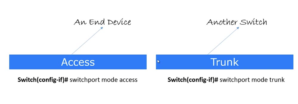
Usually, when you type the switchport mode access command, it refers to the configuration of the VLAN. However, at this point, you may not worry about VLANs; rather focus on port modes. So, this mode is used to connect a specific switch port to the end device of the user.
The second mode is known as the Trunk port, or trunk port. It is used to connect the port of one switch to another switch or router. This term was coined by Cisco, other manufacturers of network devices call it differently. When we discuss VLAN, we’ll talk about the trunk mode in more detail, for now just remember that Trunk mode is used when connecting the switch to another switch, and Access when connecting to the end device. Please note that we are not talking about switch modes, but about specific port modes, and any switch port can be configured to one of these modes.
To put a port into trunk mode, use the switchport mode trunk command. I note that when we talk about port modes, we need to say about a special protocol for these modes, which is called Dynamic Trunking protocol, DTP is a dynamic trunking protocol. This is a proprietary Cisco protocol, that is, it cannot be used with any other switches other than Cisco products. There are other manufacturers of network equipment who have adopted the concept of Cisco DTP protocol, however, since this series of video tutorials is focused on Cisco CCNA, we will not consider products from other developers.
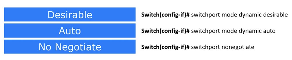
There are three modes in this protocol: two Dynamic Desirable and Dynamic Auto operating modes, and the third No Negotiate mode simply disables DTP.
If the port is in Dynamic Desirable mode, it immediately starts sending DTP packets, that is, it becomes a trunk port. It follows from the name of the protocol that it provides a trunk connection, and in this case, the name of the desirable protocol mode - “desired” - means that the port “wants” to become a trunk. Suppose I have a trunk port and you have Telnet, and maybe I want you to become a trunk port, but you don’t want to!
But if on the other side the switch port also works in Dynamic Desirable mode, then our port working in Dynamic Desirable mode becomes a trunk port. The same thing happens if our port is in Dynamic Auto mode, and the next one is in Dynamic Desirable mode. As soon as our port receives DTP packets from it, it will immediately become a trunk port.
But if both switches are in Dynamic Auto mode, a problem arises - in this mode both switches will not do anything, because this is a passive standby mode, which does not provide any actions until the port receives a DTP packet. Therefore, if both switches are in Dynamic Auto mode, no trunk trunk connection will occur.
Thus, if you want a trunk connection to be created automatically, at least one of the switches, or rather, the switch ports, must be in Dynamic Desirable mode.
However, constantly keeping one of the switches in the Dynamic Desirable state is not very good. Suppose all switches in your organization are in Dynamic Auto or Dynamic Desirable state. If some bad guy intends to crack your switch and get into the system, it will be very easy for him to do this. All he needs to do is get a switch, one of the ports of which is connected to your office switch, and set it to Dynamic Desirable mode. As soon as this happens, the company's switch will become a trunk and give an attacker the opportunity to intercept all traffic passing through it.
In trunking mode, 2 or 3 switches share the same data. This is similar to expanding the capabilities of your switch - if it has 8 ports and is connected using a trunk to another 8-port switch, consider that you have a 16-port switch. This is how trunking works by default, unless, of course, you take special measures to prevent one switch from sending its traffic to another. But usually if you organize a trunk between two 8-port switches, you just get one 16-port switch.
If a hacker gains access to your switch and creates a trunk, the company switch will start sending all traffic to the attacker's switch, which can use any software to analyze the traffic of the whole organization.
To prevent this situation, you can use the No Negotiate mode by entering the switchport nonegotiate command. Therefore, be sure to use this command to disable the DTP protocol if you are not using it.
If you use the access switch port mode, it disables trunking. As we already said, if you need a static mode of operation, you configure Access, and if you need a dynamic DTP protocol mode, you use Trunk. This is the concept of using switch port operating modes, and I hope that you have learned it.
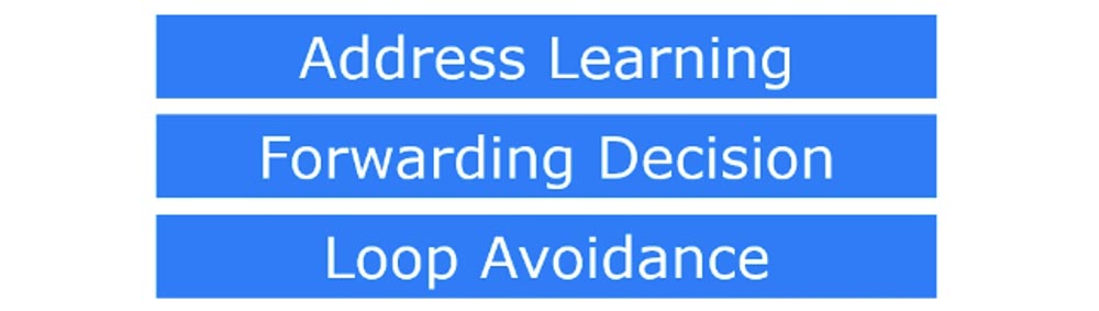
Now we turn to the consideration of the functions of communication. Basically, a switch performs three functions: Address Learning - storing MAC addresses, Forwarding Decision - making a decision to send data, and Loop Avoidance, or preventing closed loops or network loops.
Let's start by remembering the addresses. We already talked about this, but since we are talking about switches, let me remind you again. As soon as the switch is connected to the network, all network devices are connected to it within 30-40 seconds and they begin to "communicate". I’ll say that computers really like to communicate, constantly broadcasting, saying: “hey, here is my MAC address!”. Suppose we have five network devices, and each is broadcasting, for example, these may be ARP requests. Each time you turn on your computer, it reports its MAC address to the network. If the switch receives a broadcast message from the first device connected to port # 1, it reads its MAC address contained in this message and remembers that its first port is connected to this particular address. Based on this information, the switch creates an entry in its MAC address table. This table is sometimes called a CAM table, or associative memory table. In the same way, it acts in relation to the second, third, fourth, fifth network device - as soon as the switch receives a broadcast message with a MAC address, it immediately puts it into its table, creating the corresponding record.
If some network device wants to contact any MAC address, the switch checks if there is a record about this address in its table, and on the basis of this information makes a decision on sending data. Let's take a closer look at this process.
There are two types of switch transfer decisions at the second (channel) level of the OSI model - Cut Through, or through transfer, and Store & Forward, transferring with intermediate storage. Consider the difference between these two types of switching.
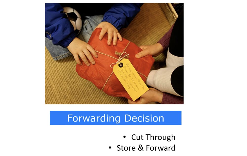
Suppose that one network device is about to communicate with another device. To do this, it sends a frame that contains its MAC address, destination MAC address, and other necessary information. As soon as the switch receives this frame, it first looks at the destination MAC address, which is in the first few bytes of the frame, and immediately transfers this frame to the destination port. This is what Cut Through switching is all about.
If the Store & Forward transfer type is used, the switch waits until it receives the entire frame. Then it checks the received frame for errors that may have occurred during the transmission. If there are no errors, it passes the frame to the destination port.
Some people think that Cut Through is enough, others say, “no, we definitely need error checking!” This question does not have a definite solution, it all depends on the specific situation. If you need fast transfer and you want the switch to forward traffic as quickly as possible, you use Cut Through switching mode. If you need more reliable, tested traffic, you use Store & Forward.
Now let's look at Loop Avoidance. As you remember, I already said in one of my lessons that when a switch receives a broadcast message, it sends it to all ports. Now I drew 2 switches and the red arrows showed the reception and transmission of data. Usually you connect one switch to another cable, forming a trunk. However, as the network grows, you are no longer satisfied with one cable through which data is transmitted, you want to speed up the traffic exchange process and connect the devices with a second cable, creating another trunk.

Of course, you can physically disconnect one cable and leave the second, and the connection between the switches will not be interrupted, however, most network administrators prefer to use both trunks. Thus, for connecting two switches, we have not one, but two ways, and such a connection can lead to a packet loop problem. It occurs when there is more than one path at the OSI model layer 2 between two endpoints, for example, when two switches have several connections to each other or two switch ports are connected to each other.
Now I will draw another device on the left - a computer. When this computer broadcasts, the switch receives traffic and forwards it to all its ports. In our case, this means that the left switch will send traffic on both the upper and lower cables, which are connected to its two ports. When the right switch receives traffic on the upper cable, it will send it to its second port, to which the lower cable is connected, and this traffic will rush back to the left switch. When traffic from the left switch on the lower cable gets to the right switch, the right switch will redirect it to its first port, and since it is a broadband transmission, it will send it on the upper cable to the left switch.

In turn, the left switch, having received traffic from the right one, will redirect it to its other port and send it back, and will do this for both ports to which the cables are connected. This process will be repeated indefinitely, that is, between the two switches a closed loop or closed loop of the same traffic is formed.
It is very difficult to detect looped traffic in the system. There are no indicators that show a traffic loop, unlike the OSI model level 3, where there are many mechanisms to prevent looping. This is because at the 2nd level of the OSI model, the headers do not support the TTL frame's lifetime value, and if the frame loops, it can live forever.
In addition, the switch MAC address table filter will be confused as to the location of the device, because the switch will receive a frame from more than one communication channel and will not be able to match it with any particular device.
The Spanning-Tree Protocol, or STP, which prevents the appearance of traffic loops in the network topology helps solve this problem. You can learn more about this protocol from the Wikipedia article, for now you just need to familiarize yourself with its concept. STP checks to see if we have a redundant connection. In our case, we have 2 connections between the same switches, that is, redundancy is present. In the following video tutorials, I will tell you in detail how STP works, but now I just say that it acts according to its own rules and logically disconnects the extra cable. Physically, both cables remain connected, but logically one of them is disconnected. Thus, both ports connected by the upper cable continue to exchange traffic, but one of the ports connected by the lower cable
Suppose the connection on the upper cable is interrupted for some reason. In this case, the STP protocol immediately includes one of the ports connected by the lower cable, and data exchange continues without interruption.
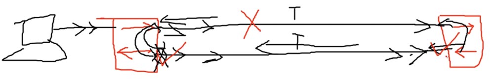
I presented you with a very brief concept of STP: it is a mechanism that disconnects redundant connections. On this slide, you see the analogy of the STP protocol - a fallen tree blocked the road and the road “broke off”.
In the following video tutorials, we will return to many topics that were briefly discussed in previous episodes. Therefore, I tell my students not to worry that we will miss something important: it’s like building a building when no one begins to paint the walls of the first floor until the rest of the floors are erected. I don’t know how many video lessons will be in our course, perhaps 40 or 50, because if a topic interests you more, I will devote a separate lesson to it. Just believe that with my help you will acquire all the knowledge to get a CCNA certificate and even learn a lot more than necessary.
Thank you for staying with us. Do you like our articles? Want to see more interesting materials? Support us by placing an order or recommending it to your friends, a 30% discount for Habr users on a unique analogue of entry-level servers that we invented for you: The whole truth about VPS (KVM) E5-2650 v4 (6 Cores) 10GB DDR4 240GB SSD 1Gbps from $ 20 or how to divide the server? (options are available with RAID1 and RAID10, up to 24 cores and up to 40GB DDR4).
Dell R730xd 2 times cheaper? Only we have 2 x Intel TetraDeca-Core Xeon 2x E5-2697v3 2.6GHz 14C 64GB DDR4 4x960GB SSD 1Gbps 100 TV from $ 199 in the Netherlands! Dell R420 - 2x E5-2430 2.2Ghz 6C 128GB DDR3 2x960GB SSD 1Gbps 100TB - from $ 99! Read aboutHow to build the infrastructure of the building. class using Dell R730xd E5-2650 v4 servers costing 9,000 euros for a penny?
Usually, when you type the switchport mode access command, it refers to the configuration of the VLAN. However, at this point, you may not worry about VLANs; rather focus on port modes. So, this mode is used to connect a specific switch port to the end device of the user.
The second mode is known as the Trunk port, or trunk port. It is used to connect the port of one switch to another switch or router. This term was coined by Cisco, other manufacturers of network devices call it differently. When we discuss VLAN, we’ll talk about the trunk mode in more detail, for now just remember that Trunk mode is used when connecting the switch to another switch, and Access when connecting to the end device. Please note that we are not talking about switch modes, but about specific port modes, and any switch port can be configured to one of these modes.
To put a port into trunk mode, use the switchport mode trunk command. I note that when we talk about port modes, we need to say about a special protocol for these modes, which is called Dynamic Trunking protocol, DTP is a dynamic trunking protocol. This is a proprietary Cisco protocol, that is, it cannot be used with any other switches other than Cisco products. There are other manufacturers of network equipment who have adopted the concept of Cisco DTP protocol, however, since this series of video tutorials is focused on Cisco CCNA, we will not consider products from other developers.
There are three modes in this protocol: two Dynamic Desirable and Dynamic Auto operating modes, and the third No Negotiate mode simply disables DTP.
If the port is in Dynamic Desirable mode, it immediately starts sending DTP packets, that is, it becomes a trunk port. It follows from the name of the protocol that it provides a trunk connection, and in this case, the name of the desirable protocol mode - “desired” - means that the port “wants” to become a trunk. Suppose I have a trunk port and you have Telnet, and maybe I want you to become a trunk port, but you don’t want to!
But if on the other side the switch port also works in Dynamic Desirable mode, then our port working in Dynamic Desirable mode becomes a trunk port. The same thing happens if our port is in Dynamic Auto mode, and the next one is in Dynamic Desirable mode. As soon as our port receives DTP packets from it, it will immediately become a trunk port.
But if both switches are in Dynamic Auto mode, a problem arises - in this mode both switches will not do anything, because this is a passive standby mode, which does not provide any actions until the port receives a DTP packet. Therefore, if both switches are in Dynamic Auto mode, no trunk trunk connection will occur.
Thus, if you want a trunk connection to be created automatically, at least one of the switches, or rather, the switch ports, must be in Dynamic Desirable mode.
However, constantly keeping one of the switches in the Dynamic Desirable state is not very good. Suppose all switches in your organization are in Dynamic Auto or Dynamic Desirable state. If some bad guy intends to crack your switch and get into the system, it will be very easy for him to do this. All he needs to do is get a switch, one of the ports of which is connected to your office switch, and set it to Dynamic Desirable mode. As soon as this happens, the company's switch will become a trunk and give an attacker the opportunity to intercept all traffic passing through it.
In trunking mode, 2 or 3 switches share the same data. This is similar to expanding the capabilities of your switch - if it has 8 ports and is connected using a trunk to another 8-port switch, consider that you have a 16-port switch. This is how trunking works by default, unless, of course, you take special measures to prevent one switch from sending its traffic to another. But usually if you organize a trunk between two 8-port switches, you just get one 16-port switch.
If a hacker gains access to your switch and creates a trunk, the company switch will start sending all traffic to the attacker's switch, which can use any software to analyze the traffic of the whole organization.
To prevent this situation, you can use the No Negotiate mode by entering the switchport nonegotiate command. Therefore, be sure to use this command to disable the DTP protocol if you are not using it.
If you use the access switch port mode, it disables trunking. As we already said, if you need a static mode of operation, you configure Access, and if you need a dynamic DTP protocol mode, you use Trunk. This is the concept of using switch port operating modes, and I hope that you have learned it.
Now we turn to the consideration of the functions of communication. Basically, a switch performs three functions: Address Learning - storing MAC addresses, Forwarding Decision - making a decision to send data, and Loop Avoidance, or preventing closed loops or network loops.
Let's start by remembering the addresses. We already talked about this, but since we are talking about switches, let me remind you again. As soon as the switch is connected to the network, all network devices are connected to it within 30-40 seconds and they begin to "communicate". I’ll say that computers really like to communicate, constantly broadcasting, saying: “hey, here is my MAC address!”. Suppose we have five network devices, and each is broadcasting, for example, these may be ARP requests. Each time you turn on your computer, it reports its MAC address to the network. If the switch receives a broadcast message from the first device connected to port # 1, it reads its MAC address contained in this message and remembers that its first port is connected to this particular address. Based on this information, the switch creates an entry in its MAC address table. This table is sometimes called a CAM table, or associative memory table. In the same way, it acts in relation to the second, third, fourth, fifth network device - as soon as the switch receives a broadcast message with a MAC address, it immediately puts it into its table, creating the corresponding record.
If some network device wants to contact any MAC address, the switch checks if there is a record about this address in its table, and on the basis of this information makes a decision on sending data. Let's take a closer look at this process.
There are two types of switch transfer decisions at the second (channel) level of the OSI model - Cut Through, or through transfer, and Store & Forward, transferring with intermediate storage. Consider the difference between these two types of switching.
Suppose that one network device is about to communicate with another device. To do this, it sends a frame that contains its MAC address, destination MAC address, and other necessary information. As soon as the switch receives this frame, it first looks at the destination MAC address, which is in the first few bytes of the frame, and immediately transfers this frame to the destination port. This is what Cut Through switching is all about.
If the Store & Forward transfer type is used, the switch waits until it receives the entire frame. Then it checks the received frame for errors that may have occurred during the transmission. If there are no errors, it passes the frame to the destination port.
Some people think that Cut Through is enough, others say, “no, we definitely need error checking!” This question does not have a definite solution, it all depends on the specific situation. If you need fast transfer and you want the switch to forward traffic as quickly as possible, you use Cut Through switching mode. If you need more reliable, tested traffic, you use Store & Forward.
Now let's look at Loop Avoidance. As you remember, I already said in one of my lessons that when a switch receives a broadcast message, it sends it to all ports. Now I drew 2 switches and the red arrows showed the reception and transmission of data. Usually you connect one switch to another cable, forming a trunk. However, as the network grows, you are no longer satisfied with one cable through which data is transmitted, you want to speed up the traffic exchange process and connect the devices with a second cable, creating another trunk.
Of course, you can physically disconnect one cable and leave the second, and the connection between the switches will not be interrupted, however, most network administrators prefer to use both trunks. Thus, for connecting two switches, we have not one, but two ways, and such a connection can lead to a packet loop problem. It occurs when there is more than one path at the OSI model layer 2 between two endpoints, for example, when two switches have several connections to each other or two switch ports are connected to each other.
Now I will draw another device on the left - a computer. When this computer broadcasts, the switch receives traffic and forwards it to all its ports. In our case, this means that the left switch will send traffic on both the upper and lower cables, which are connected to its two ports. When the right switch receives traffic on the upper cable, it will send it to its second port, to which the lower cable is connected, and this traffic will rush back to the left switch. When traffic from the left switch on the lower cable gets to the right switch, the right switch will redirect it to its first port, and since it is a broadband transmission, it will send it on the upper cable to the left switch.
In turn, the left switch, having received traffic from the right one, will redirect it to its other port and send it back, and will do this for both ports to which the cables are connected. This process will be repeated indefinitely, that is, between the two switches a closed loop or closed loop of the same traffic is formed.
It is very difficult to detect looped traffic in the system. There are no indicators that show a traffic loop, unlike the OSI model level 3, where there are many mechanisms to prevent looping. This is because at the 2nd level of the OSI model, the headers do not support the TTL frame's lifetime value, and if the frame loops, it can live forever.
In addition, the switch MAC address table filter will be confused as to the location of the device, because the switch will receive a frame from more than one communication channel and will not be able to match it with any particular device.
The Spanning-Tree Protocol, or STP, which prevents the appearance of traffic loops in the network topology helps solve this problem. You can learn more about this protocol from the Wikipedia article, for now you just need to familiarize yourself with its concept. STP checks to see if we have a redundant connection. In our case, we have 2 connections between the same switches, that is, redundancy is present. In the following video tutorials, I will tell you in detail how STP works, but now I just say that it acts according to its own rules and logically disconnects the extra cable. Physically, both cables remain connected, but logically one of them is disconnected. Thus, both ports connected by the upper cable continue to exchange traffic, but one of the ports connected by the lower cable
Suppose the connection on the upper cable is interrupted for some reason. In this case, the STP protocol immediately includes one of the ports connected by the lower cable, and data exchange continues without interruption.
I presented you with a very brief concept of STP: it is a mechanism that disconnects redundant connections. On this slide, you see the analogy of the STP protocol - a fallen tree blocked the road and the road “broke off”.
In the following video tutorials, we will return to many topics that were briefly discussed in previous episodes. Therefore, I tell my students not to worry that we will miss something important: it’s like building a building when no one begins to paint the walls of the first floor until the rest of the floors are erected. I don’t know how many video lessons will be in our course, perhaps 40 or 50, because if a topic interests you more, I will devote a separate lesson to it. Just believe that with my help you will acquire all the knowledge to get a CCNA certificate and even learn a lot more than necessary.
Thank you for staying with us. Do you like our articles? Want to see more interesting materials? Support us by placing an order or recommending it to your friends, a 30% discount for Habr users on a unique analogue of entry-level servers that we invented for you: The whole truth about VPS (KVM) E5-2650 v4 (6 Cores) 10GB DDR4 240GB SSD 1Gbps from $ 20 or how to divide the server? (options are available with RAID1 and RAID10, up to 24 cores and up to 40GB DDR4).
Dell R730xd 2 times cheaper? Only we have 2 x Intel TetraDeca-Core Xeon 2x E5-2697v3 2.6GHz 14C 64GB DDR4 4x960GB SSD 1Gbps 100 TV from $ 199 in the Netherlands! Dell R420 - 2x E5-2430 2.2Ghz 6C 128GB DDR3 2x960GB SSD 1Gbps 100TB - from $ 99! Read aboutHow to build the infrastructure of the building. class using Dell R730xd E5-2650 v4 servers costing 9,000 euros for a penny?