The simplest op-amp on discrete elements
- Transfer
- Tutorial

Discrete element operational amplifiers are available for high-end audio technology. They look like this - a board or a “sandwich” of two boards and two combs for soldering instead of an integral eight-pin dual op-amp with standard pinout. Whether the sound improves after replacement is unknown. But if the op-amp on discrete elements is greatly simplified and turned into an expanded layout, the tutorial will turn out to be excellent.
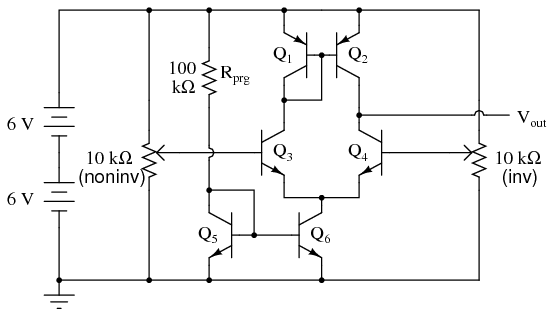
In this circuit, all transistors of the NPN structure are 2N2222 or 2N3403, PNP structures are 2N2907 or 2N3906:
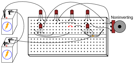
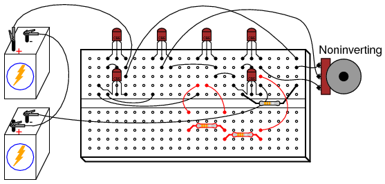
The assembly result of the circuit on the breadboard is shown on the KDPV.
In contrast to the integral op-amp, here you can see all the transistors without a microscope and name their functions. Q1 and Q2 are a current mirror that seeks to evenly distribute currents between transistors of the differential pair Q3 and Q4. Well, Q5 and Q6 are another current mirror that seeks to bring the total current through both transistors of the differential pair to the current through the resistor Rprg.
In the initial state, variable resistors are connected to the inputs of the amplifier - one to non-inverting, the second to inverting. By connecting the output of the amplifier to the input of the voltmeter, try adjusting the voltage at the inputs of the amplifier with variable resistors, and you will find that a change in the voltage at the first input does lead to a change in the voltage at the output in the same direction, and a change in the voltage at the second input leads to the opposite result. Set the same voltage at both inputs, then slightly change any of them, and note how the output voltage changes dramatically from this.
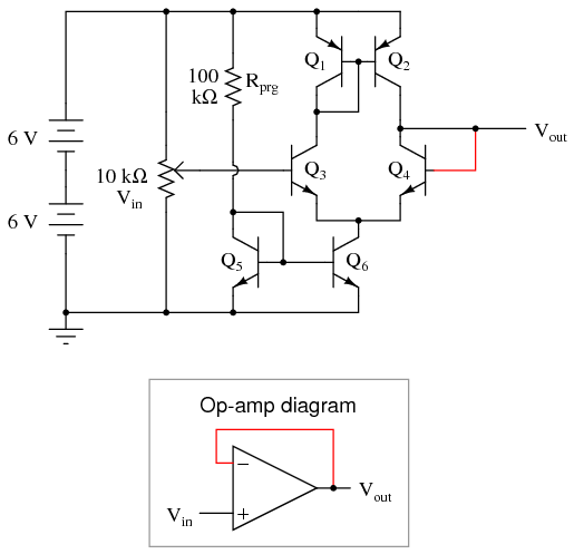
After making sure that the circuit works, try connecting the device using some standard op-amp switching circuit. Let's start with the voltage follower, for this it is necessary to connect the output to the inverting input, and apply an adjustable voltage to the non-inverting input:
On the breadboard it will look like this: By
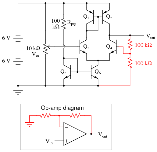
comparing the voltages at the input and output of the circuit, you will find that they differ from each other no more than several tens of millivolts. This circuit is good if gain is required not in voltage but in power. To amplify the voltage, you need to set its coefficient by adding two resistors to the feedback circuit. The voltage gain coefficient depends on the ratio of their resistances, if they are equal, this coefficient is two:
On the breadboard:
Of course, a miracle will not happen, and you cannot force the output voltage to exceed the supply voltage. But even in the range in which this circuit really doubles the voltage, you will find an inaccuracy of several tens of millivolts. You can choose a reasonable compromise between accuracy and power consumption by selecting a “programming” resistor in the range from 10 kΩ to 1 MΩ. It is impossible to set a resistor below 10 kOhm, since current mirror transistors can fail due to overheating.
For some integrated op amps, the conclusions for such “programming” are brought out. But usually this has not been done, and in this case, the resistance of the built-in "programming" resistor is what the developer considered optimal.
By eliminating the variable resistor, adding capacitors to the input and output, and setting the desired gain factor as additional resistors, you can get a headphone amplifier.