Photogram without photo paper
- Transfer
- Tutorial
Photogram is a very interesting art, at one time it was even propagandized in television programs. You place objects on photo paper, expose from the direction in which the most interesting silhouette is obtained, manifest, fix, and the work is ready. But now you cannot buy photo paper at every step. But what if, after the photograph, a digital picture is made digital?
For this, a long-known traveling-beam scanner is suitable, only today instead of a CRT it will be more convenient to use an LED matrix in it. It is even better: the tube has a slight afterglow, the LEDs do not. The sensor will be the TIL78 phototransistor, which is externally indistinguishable from the LED (the base output is not brought out, but it is not needed). This phototransistor is discontinued, it can be replaced by many similar ones.
The phototransistor must be connected by an emitter to a common wire, a collector to the input of A5 Arduino UNO, then fill in and run a small debug sketch:
#define SENSOR A5
void setup() {
  Serial.begin(9600);
  pinMode(SENSOR, INPUT_PULLUP);
}
void loop() {
  // Read analog value continuously and print it
  Serial.println(analogRead(SENSOR));
}
The program, in particular, activates the pull-up resistor built into the Arduino, so an external one is not needed. In the Arduino IDE menu, select Tools - Serial Plotter, and observe the light schedule. Since the base of the phototransistor is not indicated on it, the polarity of its connection is determined experimentally.
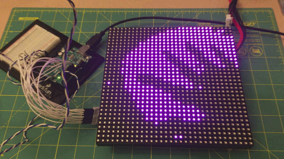
We connect the 32x32 LED matrix with the built-in control device as follows: The
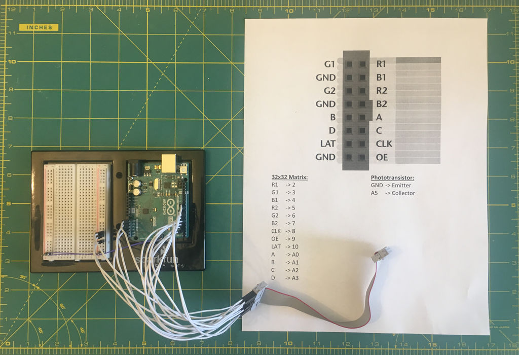
matrix cannot be powered by Arduino, it needs an external source of 5 V, 4 A. We connect it like this:

Always supply power to the matrix first, then to Arduino, remove the power in the reverse order. We “pump” the Arduino IDE with the necessary libraries and check the matrix as described here . When it works, fill in the sketch to get the photograms.
In it, you can try to vary the parameters:
static constexpr uint8_t  READINGS_PER_PIXELS = 1;
static constexpr uint8_t  THRESHOLD           = 15;
static constexpr bool     INVERT              = false;
static constexpr bool     CLEAR               = true;
The first two parameters allow you to adjust the sensitivity, the third - switch between positive and negative, and the fourth - enable the overlay of each subsequent image on the previous one. Watching a great animated GIF .
The best way to determine if light from a phototransistor came from a matrix was the following: to compare the results with the LED turned off and on. If the LED above the point of the object being read at the moment is blocked, they will be the same, if not blocked, they will be different. The LED turns on and off several times by switching the OE line (output enable), the read results are summed up in two batteries: in one - with the LED turned off, in the other - when turned on. The result of subtracting these amounts is compared with the threshold value.
The matrix contains six shift registers corresponding to whole rows of red, green and blue LEDs in the upper and lower halves. The LAT line (latch) controls a buffer that transfers values from shift registers to LED drivers. Four address lines A, B, C, D allow you to select the active line in the upper and lower halves, and the OE line makes it possible to disable and enable drivers.
Usually, previous data is stored in a buffer and sent to the LED drivers, while new data is written to shift registers at this time. After a line is completely written, they are transferred to the buffer, and the process is repeated for the next line. Even if you need to change the state of only one pixel, you have to rewrite the entire line.
Here, the matrix is used for other purposes - for scanning, so the author used the shift registers in this mode, but not the buffer. We feed one to the LAT line, and the contents of the shift register are transferred to the buffer immediately with each pulse on the CLK line. And after each dubbing, we blink an LED several times through OE to read the results by a phototransistor and add up with two batteries, as described above. Finally, after determining whether the LED is blocked, we record the result in the framebuffer provided in the library.
When the entire photogram is scanned, it will be sufficient to turn on the interrupts again - and the picture from the framebuffer will be written to the matrix in the standard way and displayed, after which it will remain there until the next scan begins.
Video: