3D Game Shaders for Beginners
- Transfer
Want to learn how to add textures, lighting, shadows, normal maps, glowing objects, ambient occlusion, and other effects to your 3D game? Excellent! This article presents a set of shading techniques that can raise the level of your game's graphics to new heights. I explain each technique in such a way that you can apply / port this information on any tool stack, be it Godot, Unity or something else.
As a “glue” between the shaders, I decided to use the magnificent game engine Panda3D and OpenGL Shading Language (GLSL). If you use the same stack, you will get an additional advantage - you will learn how to use shading techniques specifically in Panda3D and OpenGL.
Training
Below is the system I used to develop and test the sample code.
Wednesday
The sample code was developed and tested in the following environment:
- Linux manjaro 4.9.135-1-MANJARO
- OpenGL renderer string: GeForce GTX 970 / PCIe / SSE2
- OpenGL version string: 4.6.0 NVIDIA 410.73
- g ++ (GCC) 8.2.1 20180831
- Panda3D 1.10.1-1
Materials
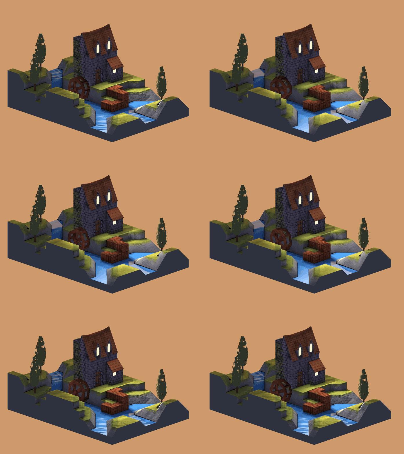
Each of the Blender materials used to create
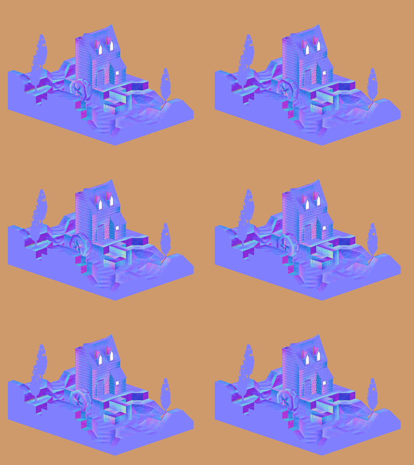
mill-scene.eggit has two textures. The first texture is a normal map, the second is a diffuse map. If an object uses the normals of its vertices, then a “plain blue” normal map is used. Due to the fact that all models have the same cards in the same positions, shaders can be generalized and applied to the root node of the scene graph.
Note that the scene graph is a feature of the Panda3D engine implementation .

Here is a one-color normal map containing only color
[red = 128, green = 128, blue = 255]. This color indicates a unit normal, indicating in the positive direction of the z axis
[0, 0, 1].[0, 0, 1] =
[ round((0 * 0.5 + 0.5) * 255)
, round((0 * 0.5 + 0.5) * 255)
, round((1 * 0.5 + 0.5) * 255)
] =
[128, 128, 255] =
[ round(128 / 255 * 2 - 1)
, round(128 / 255 * 2 - 1)
, round(255 / 255 * 2 - 1)
] =
[0, 0, 1]Here we see a unit normal
[0, 0, 1]converted to a plain blue color [128, 128, 255]and a solid blue converted to a unit normal. This is described in more detail in the section on normal map overlay techniques.
Panda3d
In this code example, Panda3D is used as the “glue” between the shaders . This does not affect the techniques described below, that is, you can use the information studied here in any selected stack or game engine. Panda3D provides certain amenities. In the article I talked about them, so you can either find their counterpart in your stack, or recreate them yourself if they are not on the stack.
It is worth considering that
gl-coordinate-system default, textures-power-2 downand textures-auto-power-2 1were added to config.prc. They are not contained in the standard Panda3D configuration . By default, Panda3D uses a right-handed coordinate system with an upward z axis, while OpenGL uses a right-handed coordinate system with an upward y axis.
gl-coordinate-system defaultallows you to get rid of transformations between two coordinate systems inside shaders. textures-auto-power-2 1allows us to use texture sizes that are not powers of two if the system supports them. This is convenient when performing SSAO or implementing other techniques within a screen / window, because the screen / window size is usually not a power of two.
textures-power-2 downreduces the size of textures to a power of two if the system only supports textures with sizes equal to powers of two.Build Example Code
If you want to run the sample code, you must first build it.
Panda3D runs on Linux, Mac, and Windows.
Linux
Start by installing the Panda3D SDK for your distribution.
Find where Panda3D headers and libraries are. Most likely, they are respectively in
/usr/include/panda3d/and in /usr/lib/panda3d/. Then clone this repository and navigate to its directory. Now compile the source code into an output file. After creating the output file, create an executable file by associating the output file with its dependencies. See the Panda3D manual for more information .
git clone https://github.com/lettier/3d-game-shaders-for-beginners.git

cd 3d-game-shaders-for-beginners
g++ \
-c main.cxx \
-o 3d-game-shaders-for-beginners.o \
-std=gnu++11 \
-O2 \
-I/usr/include/python2.7/ \
-I/usr/include/panda3d/g++ \
3d-game-shaders-for-beginners.o \
-o 3d-game-shaders-for-beginners \
-L/usr/lib/panda3d \
-lp3framework \
-lpanda \
-lpandafx \
-lpandaexpress \
-lp3dtoolconfig \
-lp3dtool \
-lp3pystub \
-lp3direct \
-lpthreadMac
Start by installing the Panda3D SDK for Mac.
Find where the headers and libraries of Panda3D are.
Then clone the repository and navigate to its directory. Now compile the source code into an output file. You need to find where the include directories are in Python 2.7 and Panda3D. After creating the output file, create an executable file by associating the output file with its dependencies. You need to find where the Panda3D libraries are located. See the Panda3D manual for more information .
git clone https://github.com/lettier/3d-game-shaders-for-beginners.git

cd 3d-game-shaders-for-beginners
clang++ \
-c main.cxx \
-o 3d-game-shaders-for-beginners.o \
-std=gnu++11 \
-g \
-O2 \
-I/usr/include/python2.7/ \
-I/Developer/Panda3D/include/clang++ \
3d-game-shaders-for-beginners.o \
-o 3d-game-shaders-for-beginners \
-L/Developer/Panda3D/lib \
-lp3framework \
-lpanda \
-lpandafx \
-lpandaexpress \
-lp3dtoolconfig \
-lp3dtool \
-lp3pystub \
-lp3direct \
-lpthreadWindows
Start by installing the Panda3D SDK for Windows.
Find where Panda3D headers and libraries are.
Clone this repository and navigate to its directory. See the Panda3D manual for more information .
git clone https://github.com/lettier/3d-game-shaders-for-beginners.git

cd 3d-game-shaders-for-beginners
Launch demo
After building the sample code, you can run the executable file or demo. This is how they run on Linux or Mac.
./3d-game-shaders-for-beginnersAnd so they run on Windows:
3d-game-shaders-for-beginners.exeKeyboard control
The demo has a keyboard control that allows you to move the camera and switch the state of various effects.
Traffic
w- move deep into the scene.a- rotate the scene clockwise.s- move away from the scene.d- rotate the scene counterclockwise.
Switchable effects
y- enable SSAO.Shift+y- disable SSAO.u- inclusion of circuits.Shift+u- disabling circuits.i- inclusion of bloom.Shift+i- disable bloom.o- inclusion of normal maps.Shift+o- disable normal maps.p- inclusion of fog.Shift+p- turn off the fog.h- inclusion of depth of field.Shift+h- disabling depth of field.j- enable posterization.Shift+j- disable posterizationk- enable pixelation.Shift+k- disable pixelization.l- the inclusion of sharpness.Shift+l- disable sharpness.ninclusion of film grain.Shift+n- disabling film grain.
Reference system
Before you start writing shaders, you need to get acquainted with the following reference systems or coordinate systems. All of them come down to what the current coordinates of the origin of the reference are taken relative to
(0, 0, 0). As soon as we find out, we can transform them using some kind of matrix or other vector space. Typically, if the output of a shader does not look right, then the cause is confused coordinate systems.Model

The coordinate system of the model or object is relative to the origin of the model. In three-dimensional modeling programs, for example, in Blender, it is usually placed at the center of the model.
World
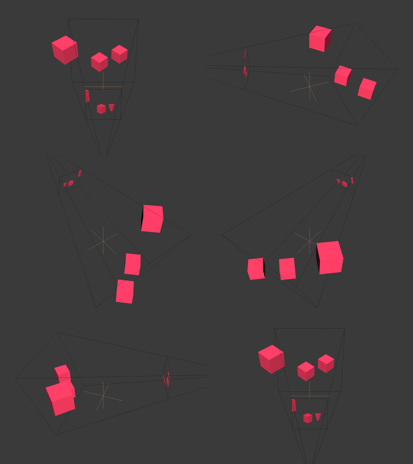
World space is relative to the origin of the scene / level / universe you created.
Overview
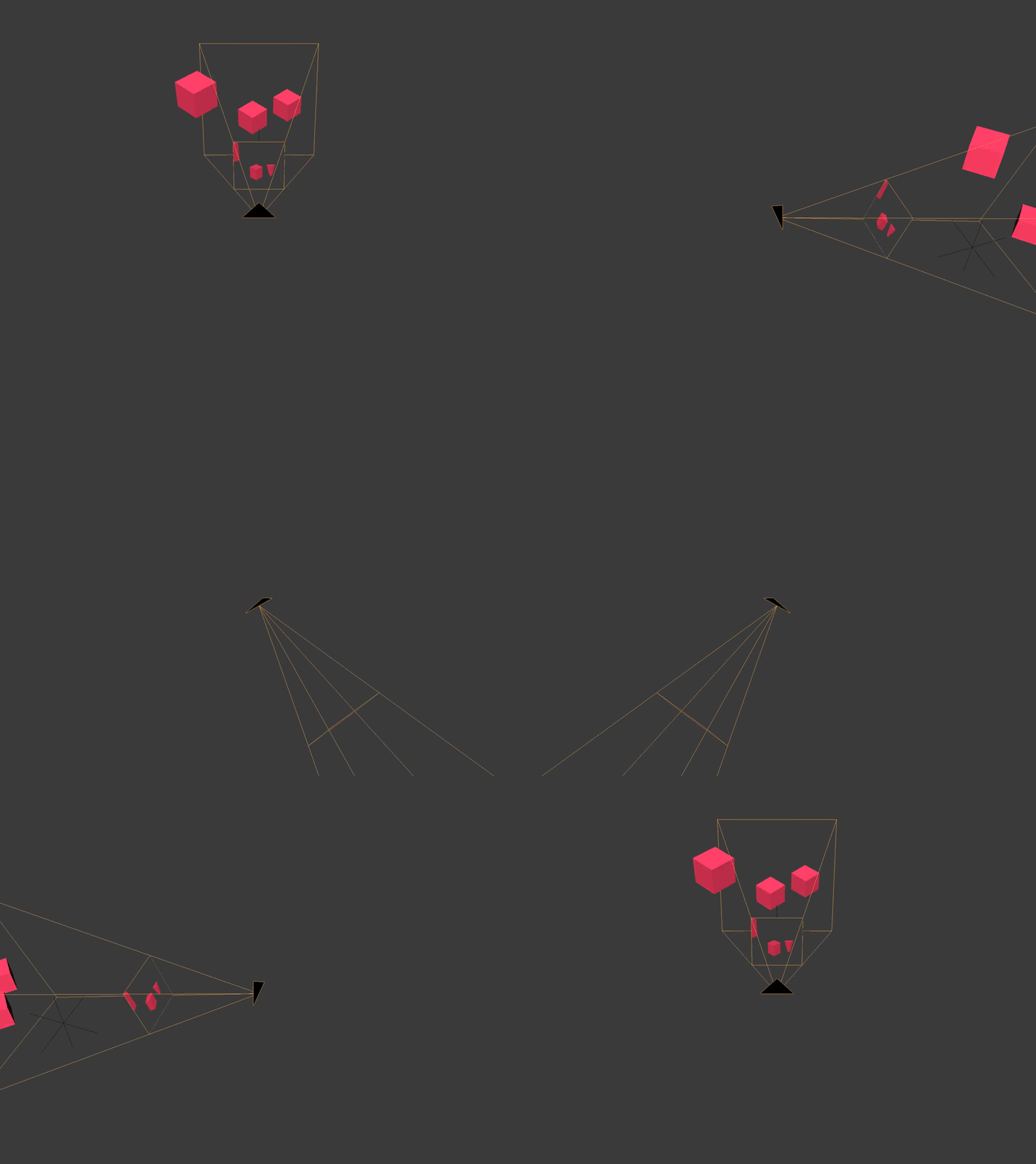
The coordinate space of the view is relative to the position of the active camera.
Clipping
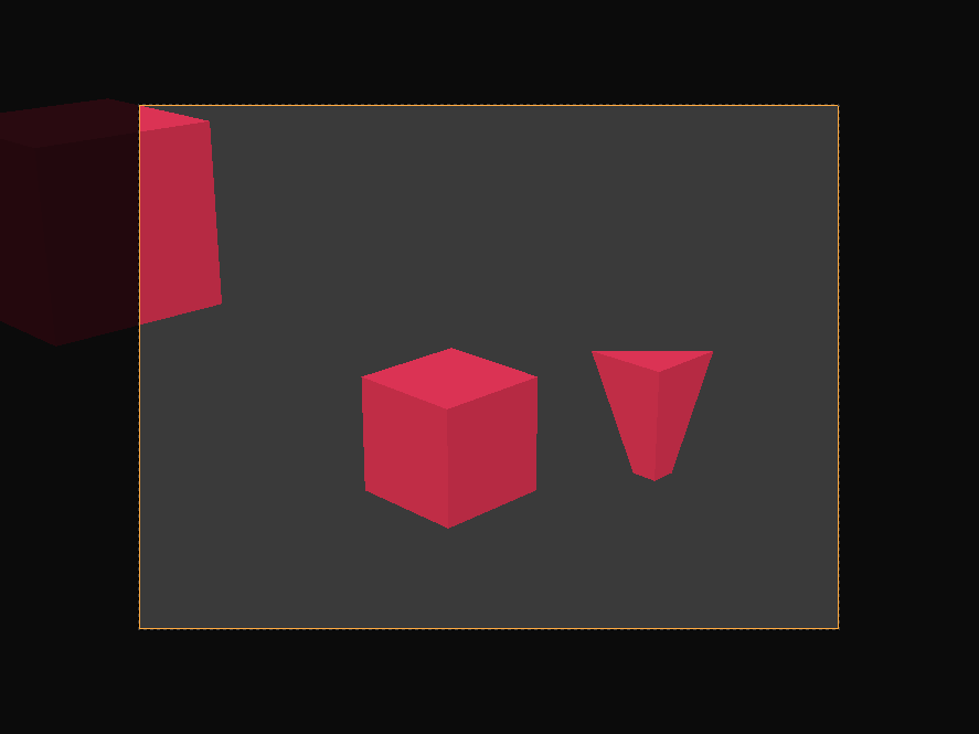
Clipping space relative to the center of the camera frame. All coordinates in it are homogeneous and are in the interval
(-1, 1). X and y are parallel to the camera film, and the z coordinate is the depth.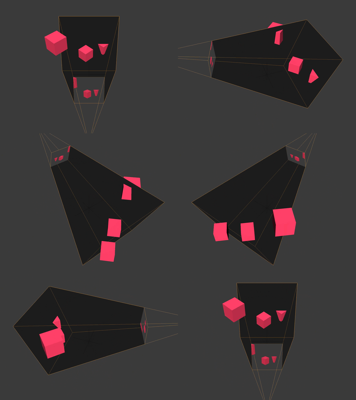
All vertices that are not within the boundaries of the pyramid of visibility or the volume of visibility of the camera are cut off or discarded. We see how this happens with a cube truncated behind by the far plane of the camera, and with a cube located on the side.
Screen
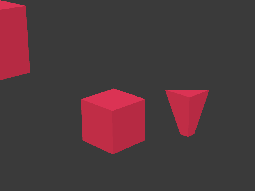
The screen space is (usually) relative to the lower left corner of the screen. X changes from zero to the width of the screen. Y changes from zero to screen height.
GLSL
Instead of working with a pipeline of fixed functions, we will use a programmable GPU rendering pipeline. Since it is programmable, we ourselves must pass it the program code in the form of shaders. A shader is a (usually small) program created with syntax resembling the C language. A programmable GPU rendering pipeline consists of various steps that can be programmed using shaders. Different types of shaders include vertex shaders, tessellation shaders, geometric, fragment and computational shaders. To use the techniques described in the article, it is enough for us to use the vertex and fragment
stages.
#version 140
void main() {}
Here is the minimal GLSL shader, consisting of the GLSL version number and the main function.
#version 140
uniform mat4 p3d_ModelViewProjectionMatrix;
in vec4 p3d_Vertex;
void main()
{
  gl_Position = p3d_ModelViewProjectionMatrix * p3d_Vertex;
}
Here is the truncated vertex shader GLSL, which transforms the input vertex into clipping space and displays this new position as a uniform vertex position.
The procedure
mainreturns nothing, because it is void, and the variable gl_Positionis the inline output. Two keywords worth mentioning are:
uniformand in. The keyword
uniformmeans that this global variable is the same for all vertices. Panda3D sets itself p3d_ModelViewProjectionMatrixand for each vertex it is the same matrix. The keyword
inmeans that this global variable is passed to the shader. A vertex shader gets each vertex that the geometry consists of, to which a vertex shader is attached.#version 140
out vec4 fragColor;
void main() {
fragColor = vec4(0, 1, 0, 1);
}Here is the trimmed GLSL fragment shader, displaying opaque green as the color of the fragment.
Do not forget that a fragment affects only one screen pixel, but several fragments can affect one pixel.
Pay attention to the keyword
out. The keyword
outmeans that this global variable is set by the shader. The name is
fragColoroptional, so you can choose any other.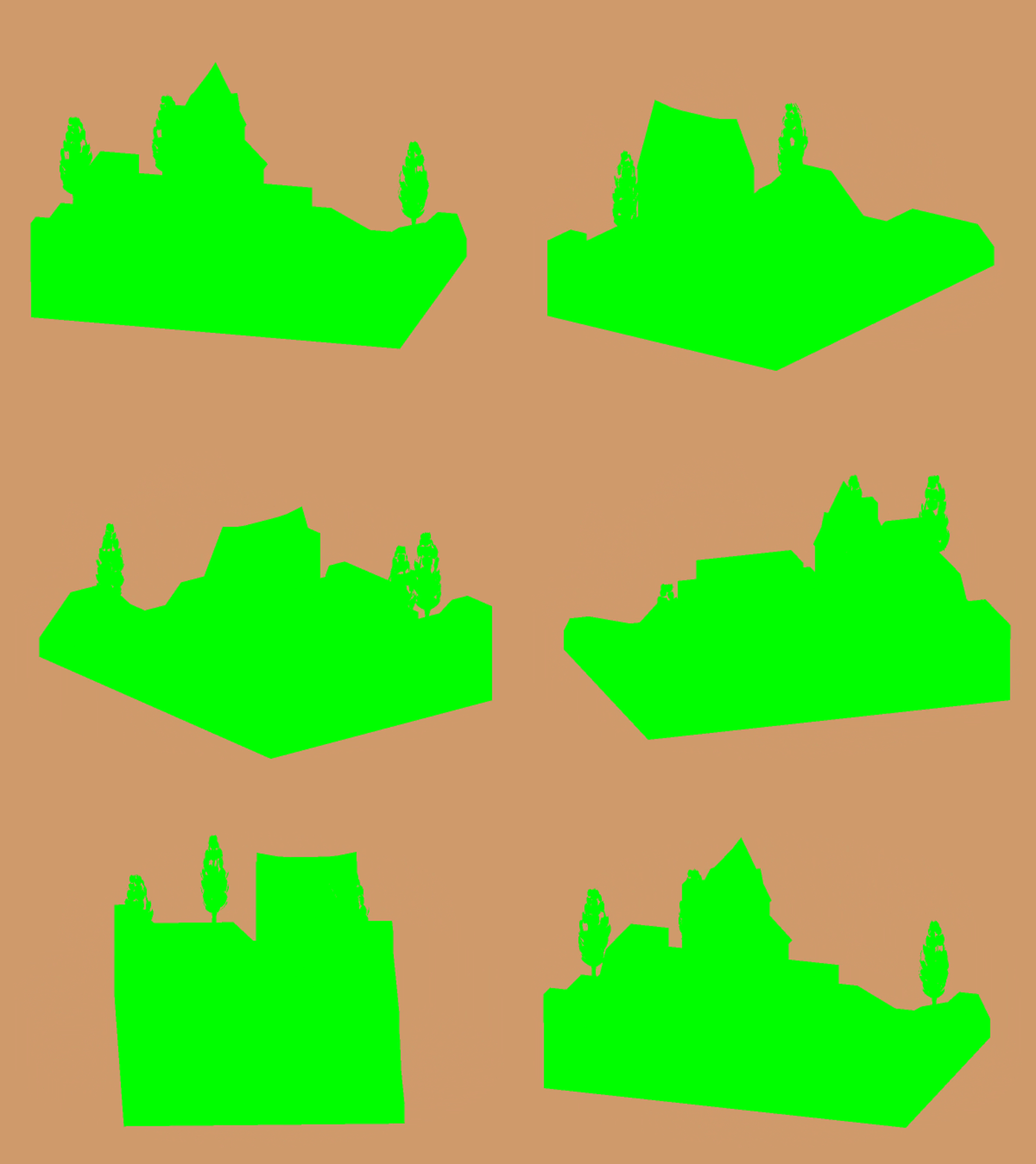
Here is the output of the two shaders shown above.
Texture rendering
Instead of rendering / drawing directly to the screen, the sample code uses a technique
called “render to texture”. To render to a texture, you need to configure the frame buffer and bind the texture to it. You can bind multiple textures to a single frame buffer.
The textures bound to the frame buffer store the vectors returned by the fragment shader. Usually these vectors are color vectors
(r, g, b, a), but they can be either positions or normal vectors (x, y, z, w). For each bound texture, a fragment shader can output a separate vector. For example, we can deduce in one pass the position and normal of the vertex. The bulk of the example code working with Panda3D is related to setting the frame buffer texture. To keep things simple, each fragment shader in the example code has only one output. However, to ensure a high frame rate (FPS), we need to output as much information as possible in each rendering pass.
Here are two texture structures for the frame buffer from the sample code.
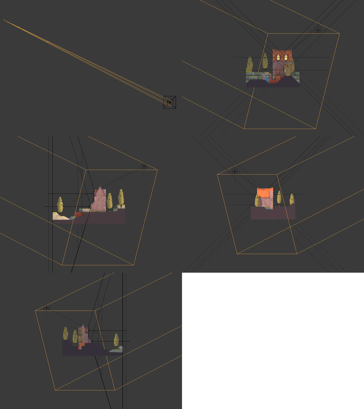
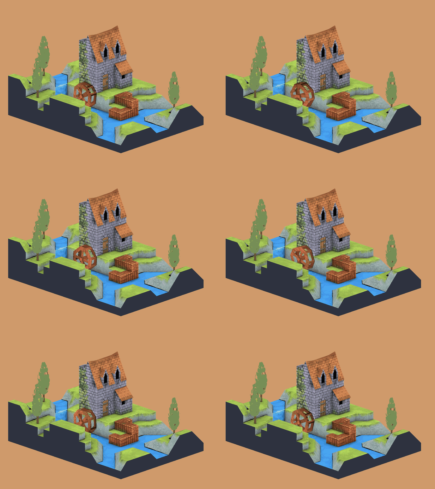
The first structure renders a watermill scene into a frame buffer texture using a variety of vertex and fragment shaders. This structure passes through each of the vertices of the stage with the mill and along the corresponding fragments.
In this structure, the example code works as follows.
- Saves geometry data (for example, position or vertex normal) for future use.
- Saves material data (e.g. diffuse color) for future use.
- Creates UV-binding of different textures (diffuse, normal maps, shadow maps, etc.).
- Calculates ambient, diffuse, reflected, and emitted lighting.
- Renders fog.
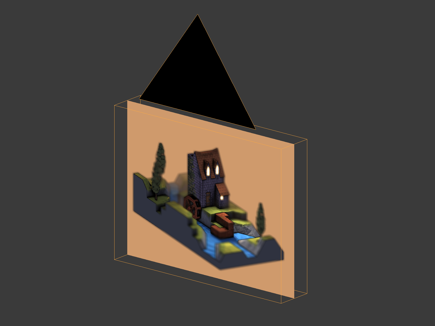
The second structure is an orthogonal camera aimed at a rectangle in the shape of a screen.
This structure runs through only four peaks and their corresponding fragments.
In the second structure, the sample code performs the following actions:
- Processes the output of another frame buffer texture.
- Combines different frame buffer textures into one.
In the code example, we can see the output of one frame buffer texture, setting the corresponding frame to true, and false to all others.
  // ...
  bool showPositionBuffer        = false;
  bool showNormalBuffer          = false;
  bool showSsaoBuffer            = false;
  bool showSsaoBlurBuffer        = false;
  bool showMaterialDiffuseBuffer = false;
  bool showOutlineBuffer         = false;
  bool showBaseBuffer            = false;
  bool showSharpenBuffer         = false;
  bool showBloomBuffer           = false;
  bool showCombineBuffer         = false;
  bool showCombineBlurBuffer     = false;
  bool showDepthOfFieldBuffer    = false;
  bool showPosterizeBuffer       = false;
  bool showPixelizeBuffer        = false;
  bool showFilmGrainBuffer       = true;
  // ...
Texturing
Texturing is the binding of a color or some other vector to a fragment using UV coordinates. The values of U and V vary from zero to one. Each vertex receives a UV coordinate and it is displayed in the vertex shader.
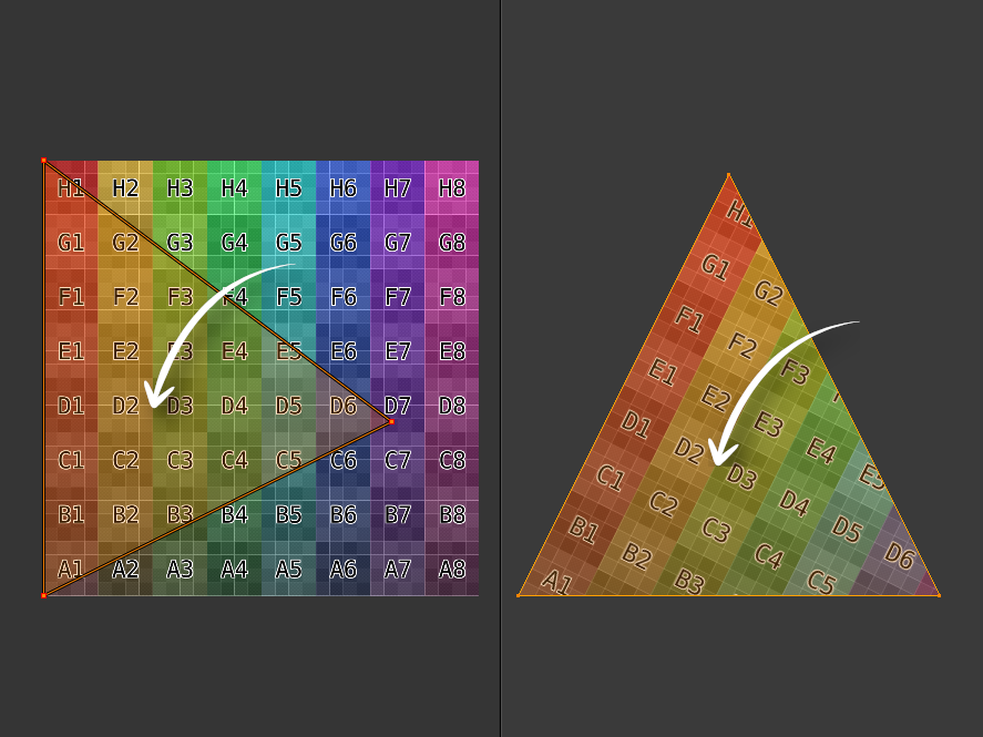
The fragment shader gets the interpolated UV coordinate. Interpolation means that the UV coordinate for the fragment is somewhere between the UV coordinates of the vertices that make up the face of the triangle.
Vertex shader
#version 140
uniform mat4 p3d_ModelViewProjectionMatrix;
in vec2 p3d_MultiTexCoord0;
in vec4 p3d_Vertex;
out vec2 texCoord;
void main()
{
  texCoord = p3d_MultiTexCoord0;
  gl_Position = p3d_ModelViewProjectionMatrix * p3d_Vertex;
}
Here we see that the vertex shader outputs the coordinate of the texture to the fragment shader. Note that this is a two-dimensional vector: one value for U and one for V.
Fragment shader
#version 140
uniform sampler2D p3d_Texture0;
in vec2 texCoord;
out vec2 fragColor;
void main()
{
  texColor = texture(p3d_Texture0, texCoord);
  fragColor = texColor;
}
Here we see that the fragment shader searches for the color in its UV coordinate and displays it as the color of the fragment.
Screen Fill Texture
#version 140
uniform sampler2D screenSizedTexture;
out vec2 fragColor;
void main()
{
  vec2 texSize  = textureSize(texture, 0).xy;
  vec2 texCoord = gl_FragCoord.xy / texSize;
  texColor = texture(screenSizedTexture, texCoord);
  fragColor = texColor;
}
When rendering to a texture, the mesh is a flat rectangle with the same aspect ratio as the screen. Therefore, we can calculate UV coordinates, knowing only
A) the width and height of the texture with the size of the screen superimposed on the rectangle using UV coordinates, and
B) the x and y coordinates of the fragment.
To bind x to U, you need to divide x by the width of the incoming texture. Similarly, to bind y to V, you need to divide y by the height of the incoming texture. You will see that this technique is used in the sample code.
Lighting
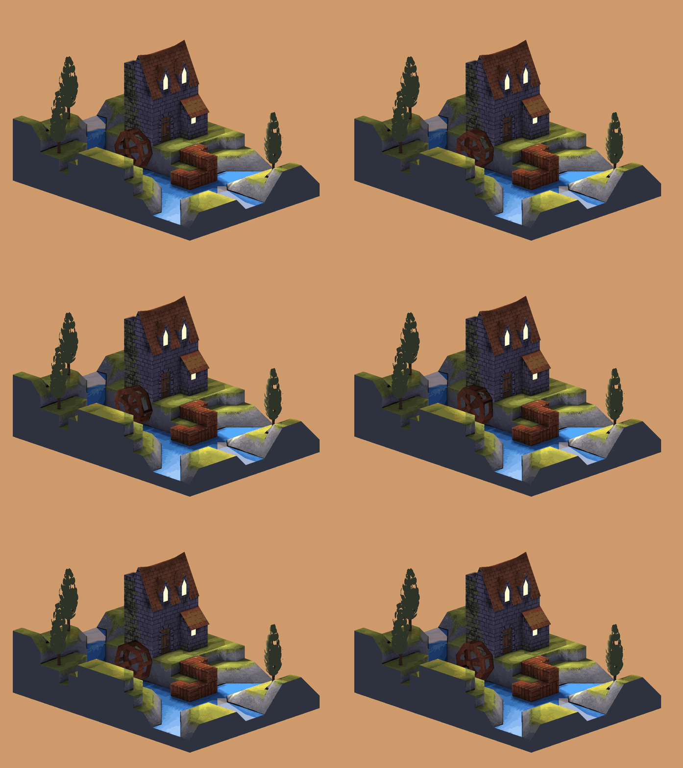
To determine the lighting, it is necessary to calculate and combine aspects of the ambient, diffuse, reflected and emitted lighting. The sample code uses Phong lighting.
Vertex shader
// ...
uniform struct p3d_LightSourceParameters
  { vec4 color
  ; vec4 ambient
  ; vec4 diffuse
  ; vec4 specular
  ; vec4 position
  ; vec3  spotDirection
  ; float spotExponent
  ; float spotCutoff
  ; float spotCosCutoff
  ; float constantAttenuation
  ; float linearAttenuation
  ; float quadraticAttenuation
  ; vec3 attenuation
  ; sampler2DShadow shadowMap
  ; mat4 shadowViewMatrix
  ;
  } p3d_LightSource[NUMBER_OF_LIGHTS];
// ...
For each light source, with the exception of ambient light, Panda3D provides us with a convenient structure that is available for both vertex and fragment shaders. The most convenient thing is a shadow map and a matrix for viewing shadows to convert vertices into a space of shadows or lighting.
  // ...
  vertexPosition = p3d_ModelViewMatrix * p3d_Vertex;
  // ...
  for (int i = 0; i < p3d_LightSource.length(); ++i) {
    vertexInShadowSpaces[i] = p3d_LightSource[i].shadowViewMatrix * vertexPosition;
  }
  // ...
Starting with the vertex shader, we must transform and remove the vertex from the viewing space into the shadow or lighting space for each light source in the scene. This will come in handy in the future for the fragment shader to render shadows. A shadow or lighting space is a space in which each coordinate is relative to the position of the light source (the origin is the light source).
Fragment shader
The fragment shader does the bulk of the lighting calculation.
Material
// ...
uniform struct
  { vec4 ambient
  ; vec4 diffuse
  ; vec4 emission
  ; vec3 specular
  ; float shininess
  ;
  } p3d_Material;
// ...
Panda3D provides us with material (in the form of a struct) for the mesh or model that we are currently rendering.
Multiple Lighting Sources
  // ...
  vec4 diffuseSpecular = vec4(0.0, 0.0, 0.0, 0.0);
  // ...
Before we go around the sources of illumination of the scene, we will create a drive that will contain both diffuse and reflected colors.
  // ...
  for (int i = 0; i < p3d_LightSource.length(); ++i) {
    // ...
  }
  // ...
Now we can go around the light sources in a cycle, calculating the diffuse and reflected colors for each.
Lighting Related Vectors
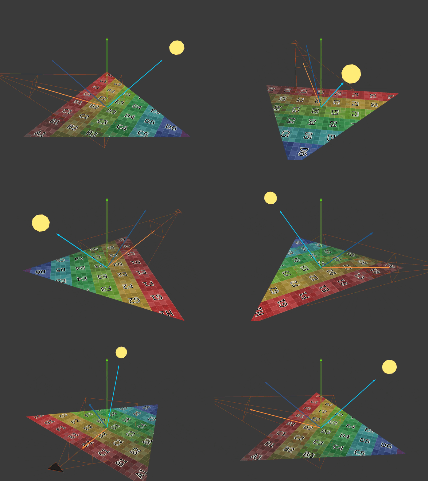
Here are four basic vectors needed to calculate the diffuse and reflected colors introduced by each light source. The lighting direction vector is a blue arrow pointing to the light source. The normal vector is a green arrow pointing vertically upward. The reflection vector is a blue arrow that mirrors the direction vector of the light. The eye or view vector is the orange arrow pointing towards the camera.
    // ...
    vec3 lightDirection =
        p3d_LightSource[i].position.xyz
      - vertexPosition.xyz
      * p3d_LightSource[i].position.w;
    // ...
The direction of lighting is the vector from the vertex position to the position of the light source.
If this is directional lighting, then Panda3D sets the
p3d_LightSource[i].position.wvalue to zero. Directional lighting has no position, only direction. Therefore, if this is directional lighting, then the direction of illumination will be a negative or opposite direction to the source, because for directional lighting Panda3D assigns a p3d_LightSource[i].position.xyzvalue -direction. // ...
normal = normalize(vertexNormal);
// ...The normal to the vertex must be a unit vector. The unit vectors have a value equal to one.
    // ...
    vec3 unitLightDirection = normalize(lightDirection);
    vec3 eyeDirection       = normalize(-vertexPosition.xyz);
    vec3 reflectedDirection = normalize(-reflect(unitLightDirection, normal));
    // ...
Next, we need three more vectors.
We need a scalar product with the participation of the lighting direction, so it is better to normalize it. This gives us a distance or magnitude equal to unity (unit vector).
The direction of view is opposite to the position of the vertex / fragment, because the position of the vertex / fragment is relative to the position of the camera. Do not forget that the position of the vertex / fragment is in the viewing space. Therefore, instead of moving from the camera (eye) to the vertex / fragment, we move from the vertex / fragment to the camera (eye).
Reflection vector- this is a reflection of the direction of lighting normal to the surface. When the "ray" of light touches the surface, it is reflected at the same angle at which it fell. The angle between the direction vector of the illumination and the normal is called the "angle of incidence." The angle between the reflection vector and the normal is called the "reflection angle".
You need to change the sign of the reflected light vector, because it should point in the same direction as the vector of the eye. Do not forget that the direction of the eye goes from the top / fragment to the position of the camera. We will use the reflection vector to calculate the brightness of the reflected light.
Diffuse lighting
    // ...
    float diffuseIntensity  = max(dot(normal, unitLightDirection), 0.0);
    if (diffuseIntensity > 0) {
      // ...
    }
    // ...
The brightness of diffuse lighting is the scalar product of the normal to the surface and the direction of illumination of a single vector. The scalar product can range from minus one to one. If both vectors point in the same direction, then the brightness is unity. In all other cases, it will be less than unity.
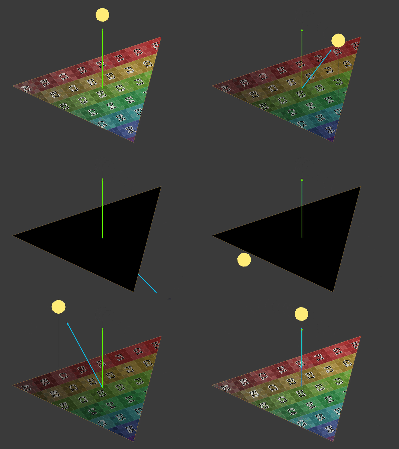
If the illumination vector approaches the same direction as normal, then the brightness of diffuse illumination tends to unity.
If the brightness of diffuse lighting is less than or equal to zero, then you need to go to the next light source.
      // ...
      vec4 diffuse =
        vec4
          ( clamp
              (   diffuseTex.rgb
                * p3d_LightSource[i].diffuse.rgb
                * diffuseIntensity
              , 0
              , 1
              )
          , 1
          );
      diffuse.r = clamp(diffuse.r, 0, diffuseTex.r);
      diffuse.g = clamp(diffuse.g, 0, diffuseTex.g);
      diffuse.b = clamp(diffuse.b, 0, diffuseTex.b);
      // ...
Now we can calculate the diffuse color introduced by this source. If the brightness of diffuse lighting is unity, then the diffuse color will be a mixture of the color of the diffuse texture and the color of the lighting. At any other brightness, the diffuse color will be darker.
Notice that I limit the diffuse color so that it is not brighter than the color of the diffuse texture. This will prevent overexposure of the scene.
Indirect lighting
After diffuse lighting, the reflected is calculated.
      // ...
      vec4 specular =
        clamp
          (   vec4(p3d_Material.specular, 1)
            * p3d_LightSource[i].specular
            * pow
                ( max(dot(reflectedDirection, eyeDirection), 0)
                , p3d_Material.shininess
                )
          , 0
          , 1
          );
      // ...
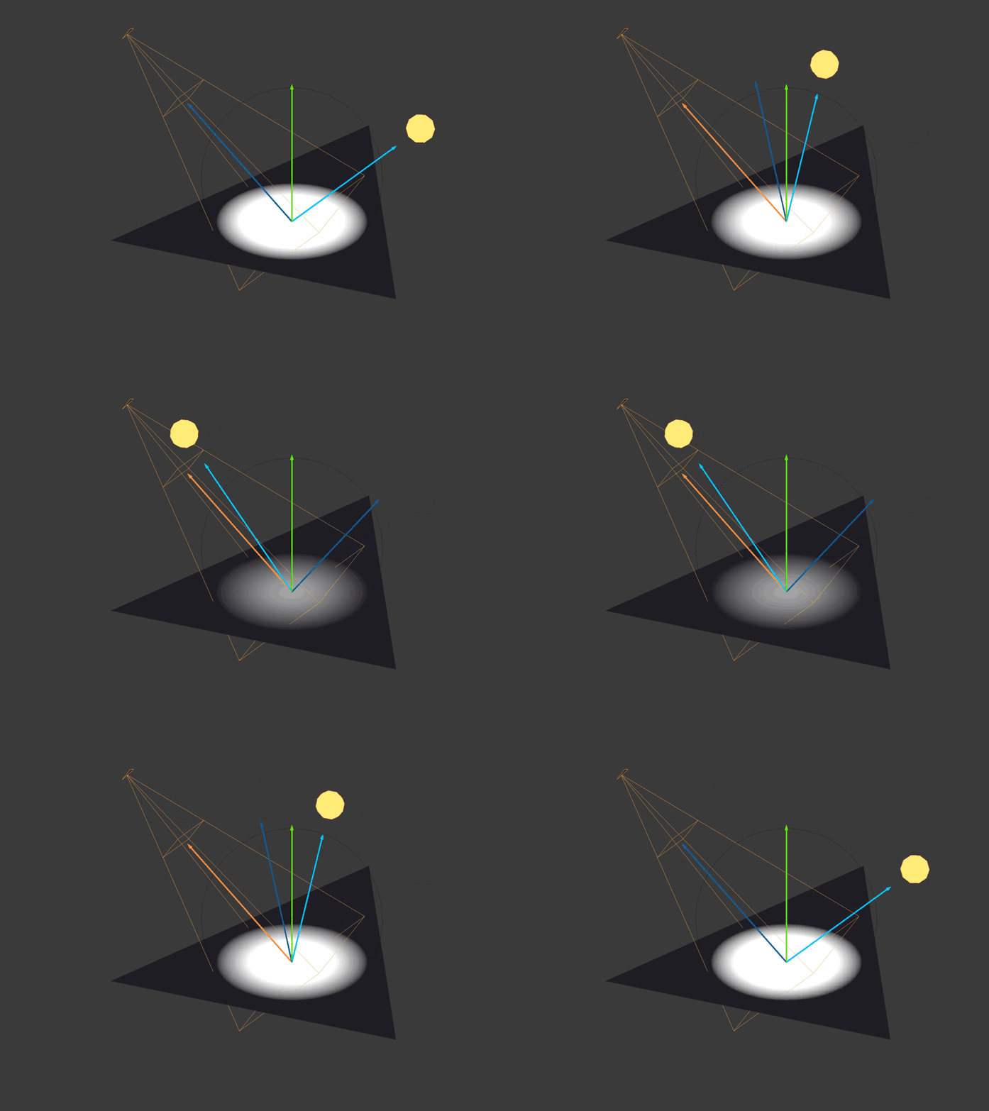
The brightness of the reflected light is the scalar product between the eye vector and the reflection vector. As in the case of the brightness of diffuse lighting, if two vectors are pointing in the same direction, then the brightness of the reflected lighting is equal to unity. Any other brightness will reduce the amount of reflected color introduced by this light source.
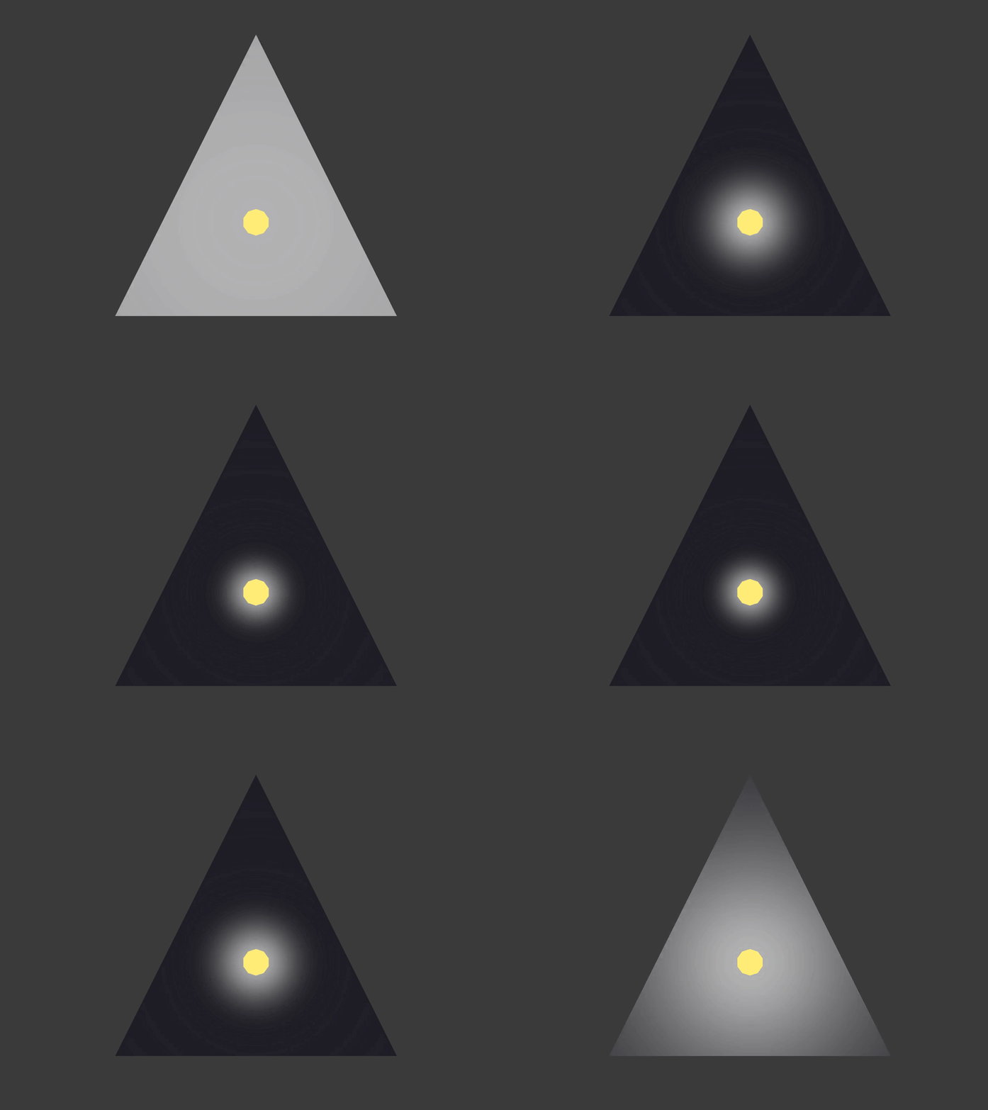
The luster of the material determines how much the illumination of the reflected light will be scattered. Usually it is set in a simulation program, for example in Blender. In Blender, it is called specular hardness.
Spotlights
      // ...
      float unitLightDirectionDelta =
        dot
          ( normalize(p3d_LightSource[i].spotDirection)
          , -unitLightDirection
          );
      if (unitLightDirectionDelta >= p3d_LightSource[i].spotCosCutoff) {
        // ...
      }
      // ...
}
This code does not allow lighting to affect fragments outside the spotlight cone or pyramid. Fortunately, Panda3D can define
spotDirection and spotCosCutoffto work with directional and spot lights. Spotlights have both a position and a direction. However, directional lighting has only direction, and point sources have only position. However, this code works for all three types of lighting without the need for confusing if statements.spotCosCutoff = cosine(0.5 * spotlightLensFovAngle);If in the case of projection lighting the scalar product of the vector "fragment-source of illumination" and the direction vector of the projector is less than the cosine of half the angle of the field of view of the
projector, then the shader does not take into account the influence of this source.
Note that you must change the sign
unitLightDirection. unitLightDirectiongoes from the fragment to the searchlight, and we need to move from the searchlight to the fragment, because it spotDirectiongoes directly to the center of the pyramid of the searchlight at a certain distance from the position of the searchlight. In the case of directional and spot lighting, Panda3D sets the
spotCosCutoffvalue to -1. Recall that the scalar product varies in the range from -1 to 1. Therefore, it does not matter what it will be unitLightDirectionDelta, because it is always greater than or equal to -1. // ...
diffuse *= pow(unitLightDirectionDelta, p3d_LightSource[i].spotExponent);
// ...Like the code
unitLightDirectionDelta, this code also works for all three types of light sources. In the case of spotlights, it will make fragments brighter as it approaches the center of the spotlight pyramid. For directional and point sources of light spotExponentis zero. Recall that any value to the power of zero is equal to unity, so the diffuse color is equal to itself, multiplied by one, that is, it does not change.Shadows
        // ...
        float shadow =
          textureProj
            ( p3d_LightSource[i].shadowMap
            , vertexInShadowSpaces[i]
            );
        diffuse.rgb  *= shadow;
        specular.rgb *= shadow;
        // ...
Panda3D simplifies the use of shadows because it creates a shadow map and shadow transformation matrix for each light source in the scene. To create a transformation matrix yourself, you need to collect a matrix that converts the coordinates of the viewing space into the lighting space (the coordinates are relative to the position of the light source). To create a shadow map yourself, you need to render the scene from the point of view of the light source into the frame buffer texture. The frame buffer texture should contain the distance from the light source to the fragments. This is called a “depth map”. Finally, you need to manually transfer to the shader your homemade depth map as
uniform sampler2DShadow, and the shadow transformation matrix as uniform mat4. So we will recreate what Panda3D does automatically for us. The code snippet shown uses
textureProjwhich differs from the function shown above texture. textureProjfirst divides vertexInShadowSpaces[i].xyzby vertexInShadowSpaces[i].w. She then uses it vertexInShadowSpaces[i].xyto find the depth stored in the shadow map. Then she uses vertexInShadowSpaces[i].zto compare the depth of the top with the depth of the shadow map in vertexInShadowSpaces[i].xy. If the comparison succeeds, it textureProjreturns one. Otherwise, it returns zero. Zero means that this vertex / fragment is in the shadow, and one means that the vertex / fragment is not in the shadow. Note that
textureProjit can also return a value from zero to one, depending on how the shadow map is configured. In this exampletextureProjPerforms multiple depth tests based on adjacent depths and returns a weighted average. This weighted average can give shadows smoothness.Attenuation
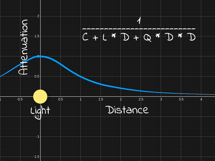
        // ...
        float lightDistance = length(lightDirection);
        float attenuation =
            1
          / ( p3d_LightSource[i].constantAttenuation
            + p3d_LightSource[i].linearAttenuation
            * lightDistance
            + p3d_LightSource[i].quadraticAttenuation
            * (lightDistance * lightDistance)
            );
        diffuse.rgb  *= attenuation;
        specular.rgb *= attenuation;
        // ...
The distance to the light source is simply the magnitude or length of the lighting direction vector. Note that we do not use the normalized direction of illumination, because such a distance would be equal to unity.
The distance to the light source is necessary to calculate the attenuation. Attenuation means that the effect of light away from the source decreases.
Parameters
constantAttenuation, linearAttenuationand quadraticAttenuationyou can set any values. It is worth starting with constantAttenuation = 1, linearAttenuation = 0and quadraticAttenuation = 1. With these parameters, in the position of the light source it is equal to unity and tends to zero when moving away from it.Final color lighting
        // ...
        diffuseSpecular += (diffuse + specular);
        // ...
To calculate the final color of lighting, you need to add the diffuse and reflected color. It is necessary to add this to the drive in a cycle of bypassing the light sources in the scene.
Ambient
// ...
uniform sampler2D p3d_Texture1;
// ...
uniform struct
  { vec4 ambient
  ;
  } p3d_LightModel;
// ...
in vec2 diffuseCoord;
  // ...
  vec4 diffuseTex  = texture(p3d_Texture1, diffuseCoord);
  // ...
  vec4 ambient = p3d_Material.ambient * p3d_LightModel.ambient * diffuseTex;
// ...
The ambient lighting component in the lighting model is based on the ambient color of the material, the color of the ambient lighting, and the color of the diffuse texture.
There should never be more than one ambient light source, therefore this calculation should be performed only once, in contrast to the calculations of diffuse and reflected colors accumulated for each light source.
Please note that the color of the ambient light comes in handy when performing SSAO.
Putting it all together
  // ...
  vec4 outputColor = ambient + diffuseSpecular + p3d_Material.emission;
  // ...
The final color is the sum of the ambient color, diffuse color, reflected color, and emitted color.
Source code
Normal Maps
Using normal maps allows you to add new parts to the surface without additional geometry. Typically, when working in a 3D modeling program, high and low poly versions of the mesh are created. Then the normals of the vertices from the high poly mesh are taken and baked into the texture. This texture is a normal map. Then inside the fragment shader we replace the normals of the vertices of the low poly mesh with the normals of the high poly mesh baked into the normal map. Due to this, when lighting a mesh, it will seem that it has more polygons than it actually is. This allows you to maintain high FPS, while transmitting most of the details from the high-poly version.
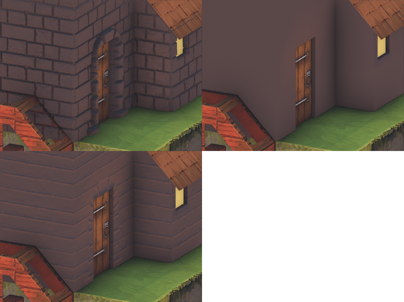
Here we see the transition from a high poly model to a low poly model, and then to a low poly model with a normal map superimposed.
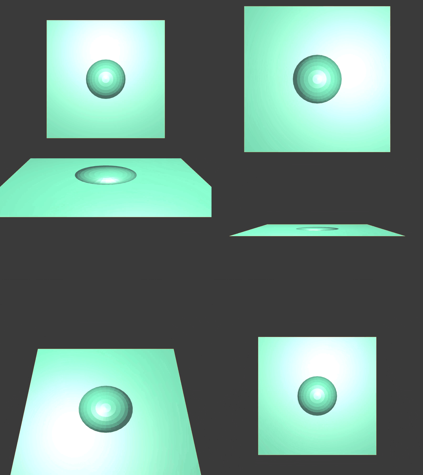
However, do not forget that overlaying a normal map is just an illusion. At a certain angle, the surface begins to look flat again.
Vertex shader
// ...
uniform mat3 p3d_NormalMatrix;
// ...
in vec3 p3d_Normal;
// ...
in vec3 p3d_Binormal;
in vec3 p3d_Tangent;
  // ...
  vertexNormal = normalize(p3d_NormalMatrix * p3d_Normal);
  binormal     = normalize(p3d_NormalMatrix * p3d_Binormal);
  tangent      = normalize(p3d_NormalMatrix * p3d_Tangent);
  // ...
Starting with the vertex shader, we need to output the normal vector, binormal vector, and tangent vector to the fragment shader. These vectors are used in the fragment shader to transform the normal of the normal map from the tangent space to the viewing space.
p3d_NormalMatrixconverts the normal vectors of the vertex, binormal, and tangent vector to the viewing space. Do not forget that in the viewing space all coordinates are relative to the position of the camera.[p3d_NormalMatrix] are the top 3x3 reverse transpose elements of ModelViewMatrix. This structure is used to convert the normal vector to the coordinates of the viewing space.
A source
// ...
in vec2 p3d_MultiTexCoord0;
// ...
out vec2 normalCoord;
  // ...
  normalCoord   = p3d_MultiTexCoord0;
  // ...
We also need to output the UV coordinates of the normal map to the fragment shader.
Fragment shader
Recall that the vertex normal was used to calculate the lighting. However, to calculate the lighting, the normal map gives us other normals. In the fragment shader, we need to replace the normals of the vertices with the normals located in the normal map.
// ...
uniform sampler2D p3d_Texture0;
// ...
in vec2 normalCoord;
  // ...
  /* Find */
  vec4 normalTex   = texture(p3d_Texture0, normalCoord);
  // ...
Using the coordinates of the normal map transferred by the vertex shader, we extract the corresponding normal from the map.
  // ...
  vec3 normal;
    // ...
    /* Unpack */
    normal =
      normalize
        ( normalTex.rgb
        * 2.0
        - 1.0
        );
    // ...
Above, I showed how normals are converted to colors to create normal maps. Now we need to reverse this process so that we can get the original normals baked to the map.
[ r, g, b] =
  [ r * 2 - 1, g * 2 - 1, b * 2 - 1] =
    [ x, y, z]
Here's what the process of unpacking normals from the normal map looks like.
    // ...
    /* Transform */
    normal =
      normalize
        ( mat3
            ( tangent
            , binormal
            , vertexNormal
            )
        * normal
        );
    // ...
The normals obtained from the normal map are usually in tangent space. However, they can be in another space. For example, Blender allows you to bake normals in tangent space, object space, world space, and camera space.
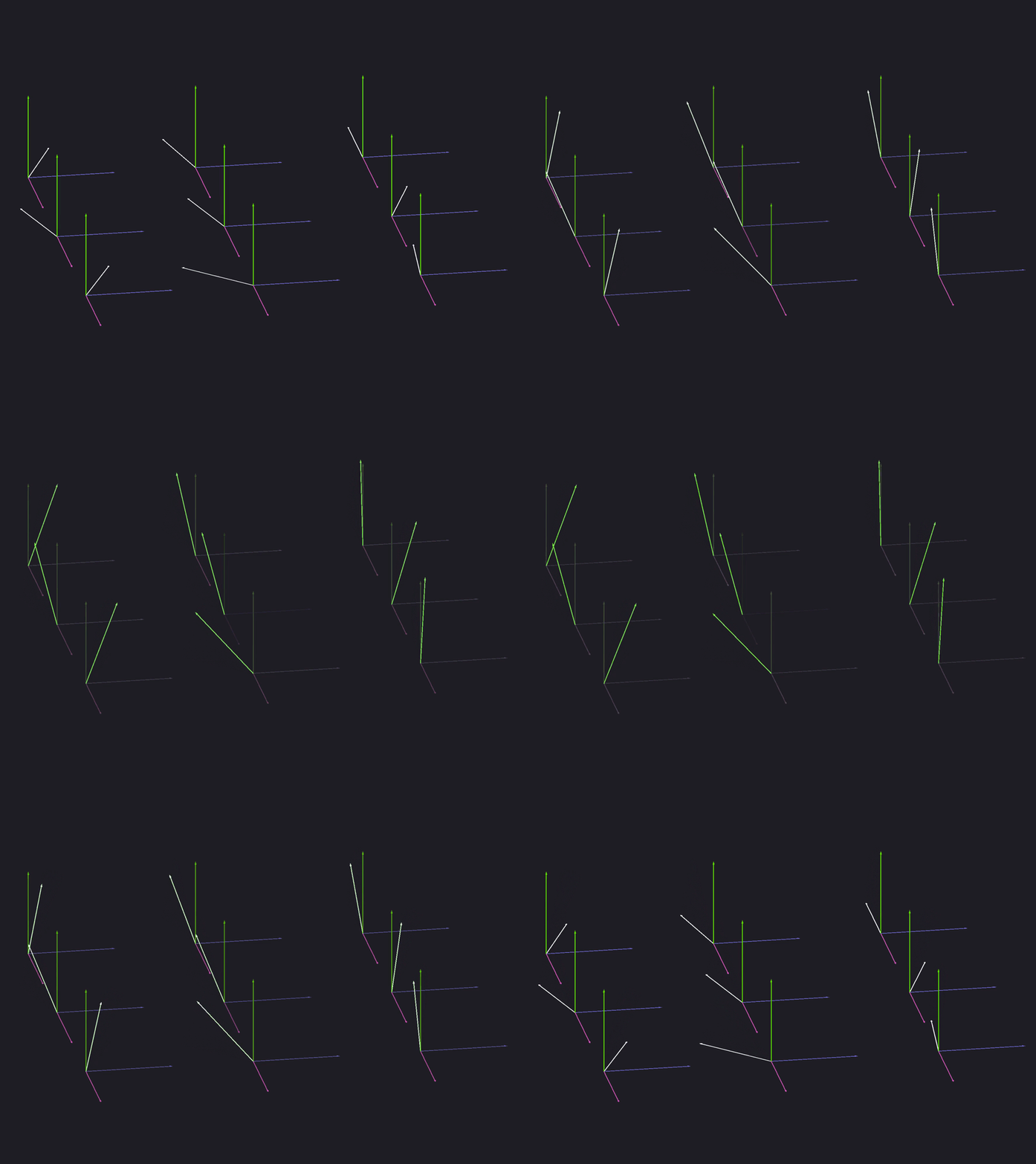
To transfer the normal of the normal map from the tangent space to the viewing space, create a 3x3 matrix based on the tangent vector, binormal vectors, and vertex normal. Multiply the normal by this matrix and normalize it. This is where we ended up with the normals. All other lighting calculations are still performed.
